Downloaded 45 times

![8
2.4 Attributes of Digital Image Watermarking
The requirements for image watermarking can be treated as characteristics, properties or
attributes of image watermarking. Different applications demand different properties of
watermarking. Requirements of image watermarking vary and result in various design issues
depending on image watermarking applications and purpose [4]. These requirements need to be
taken into consideration while designing watermarking system. There are basic five requirements
as follows.
Fidelity:
Fidelity can be considered as a measure of perceptual transparency or imperceptibility of
watermark. It refers to the similarity of un-watermarked and watermarked images. This
perspective of watermarking exploits limitation of human vision. Watermarking should not
introduce visible distortions as it reduces commercial value of the watermarked image.
Robustness:
Watermarks should not be removed intentionally or unintentionally by simple image
processing operations Hence watermarks should be robust against variety of such attacks. Robust
watermarks are designed to resist normal processing. On the other hand, fragile watermarks are
designed to convey any attempt to change digital content.
Data Payload:
Data payload is also known as capacity of watermarking. It is the maximum amount of
information that can be hidden without degrading image quality. It can be evaluated by the
amount of hidden data. This property describes how much data should be embedded as a
watermark so that it can be successfully detected during extraction
Security:
Secret key has to be used for embedding and detection process in case security is a major
concern. There are three types of keys used in watermark systems: private-key, detection-key](https://image.slidesharecdn.com/prcreport-140516203500-phpapp01/85/Optical-Watermarking-Literature-survey-8-320.jpg)
![15
3.2 Techniques Used in Existing System
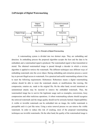
Discrete Cosine Transform:
The DCT is the most popular transform function used in signal processing. It transforms
a signal from spatial domain to frequency domain. Due to good performance, it has been used in
JPEG standard for image compression. It is a function represents a technique applied to image
pixels in branded. DCT techniques are more robust compared to spatial domain techniques. Such
algorithms are robust against simple image processing operations like adjustment, brightness,
blurring, contrast and low pass filtering and so on[3]. But it is difficult to implement and
computationally more expensive. The one-dimensional DCT is useful in processing one
dimensional signals such as speech waveforms. For analysis of two-dimensional (2D) signals
such as images, we need a 2D version of the DCT. The 2D DCT and 2D IDCT transforms is
given by equation 1 and 2.
Formulae of 2-D DCT:
………………… (1)
Formulae of 2-D inverse DCT:
……………….. (2)
Where,](https://image.slidesharecdn.com/prcreport-140516203500-phpapp01/85/Optical-Watermarking-Literature-survey-15-320.jpg)
![20
3.3 Trouble in Present or Existing System
The above described techniques excluding Fourier transform, DWT suffer from 4
fundamental, intertwined shortcomingsproblems they are
Problem 1: Shift Variance
Problem 2: Oscillations
Problem 3: Aliasing
Problem 4: Lack of Directionality
Problem 1: Shift Variance:
A small shift of the signal greatly perturbs the wavelet coefficient oscillation pattern
around singularities Shift variance also complicates wavelet-domain processing algorithms must
be made capable of coping with the wide range of possible wavelet coefficient patterns caused
by shifted singularities, To better understand wavelet coefficient oscillations and shift variance,
consider a piecewise smooth signal x(t− t0) like the step function
analyzed by a wavelet basis having a sufficient number of vanishing moments[6]. Its wavelet
coefficients consist of samples of the step response of the wavelet](https://image.slidesharecdn.com/prcreport-140516203500-phpapp01/85/Optical-Watermarking-Literature-survey-20-320.jpg)
![21
where is the height of the jump. Since ψ(t ) is a bandpassfunction that oscillates around
zero, so does its step response d( j, n) as a function of n (recall Figure 1). Moreover, the factor 2 j
in the upper limit ( j≥ 0) amplifies the sensitivity of d( j, n)to the time shift t0, leading to strong
shift variance.
Problem 2: Oscillations
Since wavelets are bandpass functions, the wavelet coefficients tend to oscillate positive
and negative around singularities. This considerably complicates wavelet-based processing,
making singularity extraction and signal modeling, in particular very challenging [22].
Moreover, since an oscillating function passes often through zero, we see that the conventional
wisdom that singularities yield large wavelet coefficients is overstated. Indeed, it is quite
possible for a wavelet overlapping a singularity to have a small or even zero wavelet coefficient.
PROBLEM 3: ALIASING
The wide spacing of the wavelet coefficient samples, or equivalently, the fact that the
wavelet coefficients are computed via iterated discrete-time downsampling operations
interspersed with nonideal low-pass and high-pass filters, results in substantial aliasing. The
inverse DWT cancels this aliasing, of course, but only if the wavelet and scaling coefficients are
not changed[6]. Any wavelet coefficient processing (thresholding, filtering, and quantization)
upsets the delicate balance between the forward and inverse transforms, leading to artifacts in the
reconstructed signal.
PROBLEM 4: LACK OF DIRECTIONALITY
Finally, while Fourier sinusoids in higher dimensions correspond to highly directional
plane waves, the standard tensor product construction of M-D wavelets produces a checkerboard](https://image.slidesharecdn.com/prcreport-140516203500-phpapp01/85/Optical-Watermarking-Literature-survey-21-320.jpg)


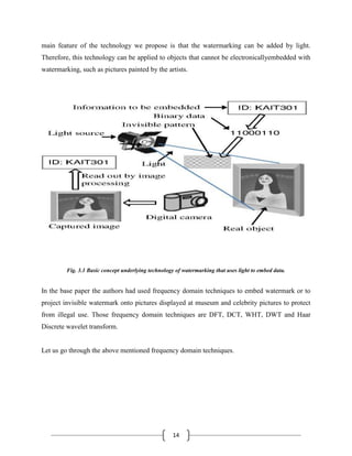
1. The document discusses optical watermarking, a technique for protecting copyright of real-world objects like artwork by embedding watermarks in the illumination of the objects. When photos are taken of the illuminated objects, the watermarks are captured in the digital images and can be extracted. 2. Optical watermarking works by transforming binary data into patterns of light projected onto objects. The patterns differ based on 1s and 0s in the data. When photos of the illuminated objects are taken, the patterns can be read from the captured images. Visible light is used with fine or low-contrast patterns to make the watermarks imperceptible. 3. Optical watermarking provides copyright protection for valuable


