The project presents multi focus image fusion using discrete wavelet transform with local directional pattern and spatial frequency analysis. Multi focus image fusion in wireless visual sensor networks is a process of blending two or more images to get a new one which has a more accurate description of the scene than the individual source images. In this project, the proposed model utilizes the multi scale decomposition done by discrete wavelet transform for fusing the images in its frequency domain. It decomposes an image into two different components like structural and textural information. It doesn’t down sample the image while transforming into frequency domain. So it preserves the edge texture details while reconstructing image from its frequency domain. It is used to reduce the problems like blocking, ringing artifacts occurs because of DCT and DWT. The low frequency sub-band coefficients are fused by selecting coefficient having maximum spatial frequency. It indicates the overall active level of an image. The high frequency sub-band coefficients are fused by selecting coefficients having maximum LDP code value LDP computes the edge response values in all eight directions at each pixel position and generates a code from the relative strength magnitude. Finally, fused two different frequency sub-bands are inverse transformed to reconstruct fused image. The system performance will be evaluated by using the parameters such as Peak signal to noise ratio, correlation and entropy
(SHREYA) Chakan Call Girls Just Call 7001035870 [ Cash on Delivery ] Pune Esc...
Blending of Images Using Discrete Wavelet Transform
1. International Journal on Recent and Innovation Trends in Computing and Communication ISSN: 2321-8169
Volume: 5 Issue: 7 427 – 434
_______________________________________________________________________________________________
427
IJRITCC | July 2017, Available @ http://www.ijritcc.org
_______________________________________________________________________________________
Blending of Images Using Discrete Wavelet Transform
Ancy.S1
Assistant Professor/Information Technology
Jeppiaar Institute of Technology
Chennai,India
sancyit@gmail.com
Maheswari.M2
Associate Professor /Information Technology
D.M.I College of Engineering
Chennai,India
maheshwari.mns@gmail.com
Abstract— The project presents multi focus image fusion using discrete wavelet transform with local directional pattern and spatial frequency
analysis. Multi focus image fusion in wireless visual sensor networks is a process of blending two or more images to get a new one which has a
more accurate description of the scene than the individual source images. In this project, the proposed model utilizes the multi scale
decomposition done by discrete wavelet transform for fusing the images in its frequency domain. It decomposes an image into two different
components like structural and textural information. It doesn’t down sample the image while transforming into frequency domain. So it
preserves the edge texture details while reconstructing image from its frequency domain. It is used to reduce the problems like blocking, ringing
artifacts occurs because of DCT and DWT. The low frequency sub-band coefficients are fused by selecting coefficient having maximum spatial
frequency. It indicates the overall active level of an image. The high frequency sub-band coefficients are fused by selecting coefficients having
maximum LDP code value LDP computes the edge response values in all eight directions at each pixel position and generates a code from the
relative strength magnitude. Finally, fused two different frequency sub-bands are inverse transformed to reconstruct fused image. The system
performance will be evaluated by using the parameters such as Peak signal to noise ratio, correlation and entropy
__________________________________________________*****_________________________________________________
I. INTRODUCTION
1.1 OVERVIEW OF DIGITAL IMAGE PROCESSING
:
Image processing is a method to convert an image
into digital form and perform some operations on it, in order
to get an enhanced image or to extract some useful
information from it. It is a type of signal dispensation in
which input is image, like video frame or photograph and
output may be image or characteristics associated with that
image. The process used for the identification of objects in
an image. This process would probably start with image
processing techniques such as noise removal i.e., filtering,
followed by (low-level) feature extraction to locate lines,
regions and possibly areas with certain textures. The clear
bits interpret the shapes of single objects, e.g. Cars on a
road, boxes on a conveyor belt or cancerous cells on a
microscope slide.
One reason, which leads to a problem, is that an
object can appear very different when viewed from different
angles or under different lighting. Another problem is
deciding what features belong to what object and which are
background or shadows etc. The human visual system
performs these tasks mostly unconsciously but a computer
requires skillful programming and lots of processing power
to approach with human performance. Manipulating data in
the form of an image through several possible techniques is
required to process the image. An image is usually
interpreted as a two-dimensional array of brightness values,
and is most familiarly represented by such patterns as those
of a photographic print, slide, television screen, or movie
screen. An image can be processed optically or digitally
with a computer. Image fusion has become a commonly-
used technology to increase the visual interpretation of the
images in various applications like enhanced vision system,
machine vision, medical diagnosis, robotics, military and
surveillance, to name a few. The main aim of any image
fusion algorithm is to coalesce all the important visual
information from multiple input images such that the
resultant image contains more accurate and complete
information than the individual source images, without
introducing any artifacts. Hence, the fused image is more
suitable for machine/human perception as well as for further
processing.
Usually image processing system includes treating
images as two dimensional signals while applying already
set signal processing methods to them. Applications of
image processing are Image Sharpening and restoration,
Medical field, remote sensing, Transmission and encoding,
machine /robot vision, colour processing, pattern
recognition, video processing, Microscopic imaging, etc.
The two types of methods used for Image Processing are
Analog and Digital Image Processing .
i).Analog image processing is done on analog
signals. It includes processing on two dimensional analog
signals. In this type of processing, the images are
manipulated by electrical means by varying the electrical
signal.
ii).The digital image processing deals with
developing a digital system that performs operations on an
digital image. Domains in image processing are:
i).FREQUENCY DOMAIN:
Whereas in frequency domain, we deal with the
rate at which the pixel values are changing in spatial
domain.
2. International Journal on Recent and Innovation Trends in Computing and Communication ISSN: 2321-8169
Volume: 5 Issue: 7 427 – 434
_______________________________________________________________________________________________
428
IJRITCC | July 2017, Available @ http://www.ijritcc.org
_______________________________________________________________________________________
ii).GRADIANT DOMAIN:
Gradient domain image processing is a relatively
new type of digital image processing that operates on the
differences between neighbouring pixels, rather than on the
pixel values directly.
APPLICATION: Gradient shop.
iii).SPATIAL DOMAIN:
In spatial domain, we deal with images as it is. The
value of the pixels of the image change with respect to
scene.
1.2 WAVELET TRANSFORM:
Wavelet transforms was used to analyze non-
stationary signals. It uses the multi-resolution technique by
which different frequencies are analyzed with different
resolution. The idea of this transform was to represent the
signal to be analyzed as a superposition of wavelets.
II. OTHER WAVELET RELATED TRANSFORMS:
i).CONTINUOUS WAVELET TRANSFORM:
The wavelet transform of a signal using CWT is
obtained by changing the scale of analysis window, shifting
the window in time, multiplying the signal and integrating
the result over all time.
ii).MULTI-RESOLUTION ANALYSIS:
It offers an efficient framework for existing
information from images at various levels of resolution.
iii).DISCRETE WAVELET TRANSFORM:
DWT is obtained by filtering the signal through a
series of digital filters at different scales. The scaling
operation is done by changing the resolution of signal by the
process of sub-sampling. The DWT can be computed using
either convolution based or lifting based procedures.
Translation will be done at integer point. Wavelets used are
orthogonal and bi-orthogonal.
APPLICATIONS:
a. Compression: Compression is a process of minimizing
the size of the graphic file without degrading the quality of
image to an unacceptable level.
b. De-noising.
c. Transmission.
III. CLASSIFICATION OF IMAGES:
There are 3 types of images used in Digital Image
Processing. They are 1. Binary Image 2. Gray Scale Image
3. Color Image.
1. BINARY IMAGE :
A binary image is a digital form of image with is
provided with two values for each pixel of the image.
Typically the two colors used for a binary image are black
and white though any two colors can be used. It contains
foreground color as white and background color as black.
Bi-level or two-level images are binary image. This means
that each pixel is stored as a single bit (0 or 1).This name
black and white, monochrome or monochromatic are often
used for this concept, but may also designate any images
that have only one sample per pixel.
Binary images often occur in digital image
processing technique as masks or as the result of certain
operations such as segmentation, threshold, and dithering.
Some input/output devices, such as laser printers, fax
machines, and bi-level computer displays, can only handle
bi-level images.
1.3.2 GRAY SCALE IMAGE :
A grayscale Image is a form of digital image in
which the value of each pixel represented in the image is a
single sample, that is, it carries and explains only the
information related to the intensity of the image. Images of
this 5 sort, also known as black-and-white, are composed
exclusively of shades of color gray (0-255), varying from
black (0) at the weakest intensity to white (255) at the
strongest. Grayscale images are distinct from one-bit black-
and-white images, which in the context of computer imaging
are images with only the two colors, black, and white (also
called bi-level or binary images). Grayscale images have
many shades of gray in between two different colors.
Grayscale images are also called monochromatic, denoting
the absence of any chromatic variation. Grayscale images
are often the result of measuring the intensity of light at each
pixel in a single band of the electromagnetic spectrum (e.g.
infrared, visible light, ultraviolet, etc.), and in such cases
they are monochromatic proper when only a given
frequency is captured. But also they can be synthesized from
a full color image; see the section about converting to
grayscale.
1.3.3 COLOR IMAGE:
A digital color image is also a form of a digital
image representation that includes color information for
each pixel in the image. Each pixel has a particular value
which determines it’s appearing color. This value is
qualified by three numbers giving the decomposition of the
color in the three primary colors Red, Green and Blue. Any
color visible to human eye can be represented this way. The
decomposition of a color in the three primary colors is
quantified by a number between 0 and 255. For example,
white will be coded as R = 255, G = 255, B = 255; black
will be known as (R,G,B) = (0,0,0); and say, bright pink will
be : (255,0,255). In other words, an color image is an
enormous two-dimensional array of color values, pixels,
each of them coded on 3 bytes, representing the three
primary colors.
This allows the image to contain a total of
256x256x256 =16.8 million different colors. This technique
is also known as RGB encoding, and is specifically adapted
to human vision.
ADVANTAGES:
1) It helps to describe complex scene in the single image.
2) Minimization of edge details loss due to no down
sampling.
3) Less computational complexity and better visual
perception.
3. International Journal on Recent and Innovation Trends in Computing and Communication ISSN: 2321-8169
Volume: 5 Issue: 7 427 – 434
_______________________________________________________________________________________________
429
IJRITCC | July 2017, Available @ http://www.ijritcc.org
_______________________________________________________________________________________
IV. LITERATURE REVIEW :
Blending of various images of same scene helps to
have both the key information in a single blended picture.
The accuracy of the blende image have been increased
without losing the key information. The paper called A
Universal Image Quality Index proposed a new universal
objective image quality index, which is easy to calculate and
applicable to various image processing applications. Instead
of using traditional error summation methods, the proposed
index is image distortion designed by modeling a
combination of three factors: loss of correlation, luminance
distortion, and contrast distortion. No human visual system
model is explicitly employed, our experiments of image
distortion using various image types indicate that it performs
significantly better than the widely used distortion metric
mean squared error. In this paper Image Quality
Assessment: From Error Visibility to Structural Similarity,
have summarized the traditional approach to image quality
assessment based on error-sensitivity, and its limitations
have been enumerated. They have proposed structural
similarity as an alternative motivating principle for image
quality measures of design. To demonstrate our structural
similarity concept, we developed an SSIM index have
showed that other methods are favorably compared with in
accounting for our experimental measurements of subjective
quality of 344 JPEG and JPEG2000 compressed images.
Fusing Images with different focuses using support vector
machines is a paper which improved the fusion procedure by
applying the discrete wavelet frame transform (DWFT) and
the support vector machines (SVM).
Unlike Discrete wavelet transform, Discrete
wavelet Fourier Transform yields a translation-invariant
signal representation. Using features extracted from the
DWFT coefficients, the source images are selected from a
SVM which is trained for the best focus at each pixel
location, and the corresponding DWFT coefficients are then
incorporated into the composite wavelet representation. The
proposal of extending the depth of field in microscopy
through curvelet-based frequency –adaptive image fusion
had given a curvelet-based image fusion method that is
frequency-adaptive. Because of the high directional
sensitivity of the curvelet transform (and consequentially, its
extreme sparseness), the average performance gain of the
new method over state-of-the-art methods is high.
Using recent complex extensions of EMD which
guarantees the same number of decomposition levels, that is
the uniqueness of the scales. The methodology is used to
address multifocus image fusion, whereby two or more
partially defocused images are combined in automatic
fashion so as to create all in focused image have been
proposed in Multiscale Image Fusion Using Complex
Extensions of EMD. In A Total Variation-Based Algorithm
for Pixel-Level Image Fusion paper, a total variation (TV)
based approach is proposed for pixel-level fusion to fuse
images acquired using multiple sensors. In this approach,
fusion is posed as an inverse problem and a locally affine
model is used as the forward model. A TV seminorm based
approach in conjunction with principal component analysis
is used iteratively to estimate the fused image. A
Combination of images with diverse focuses using the
spatial gives an approach of which combines image with
diverse focuses by decomposing the image of source into
blocks first and after that combining them with the help of
the spatial frequency. The algorithm is simple and will be
performed in real-time applications. Wide experiments on
studying the performance of fusion with different block size
and threshold need to be made have been proposed. The
resultant image in Multifocus image fusion using region
segmentation and spatial frequency consists of more precise
description of the scene than the other individual image. A
new region proposed was based on the multi-focused image
fusion method. The method proposed exists in the fact in
which the region-based image fusion method will be more
meaningful than the pixel-based fusion method. The
combining groups of pixels forms an image region was
based on the fusion rules. The proposed JPEG still picture
compression standard for JPEG was generic, for continuous
tone image an wide variety of applications are supported.
The emerging JPEG continuous-tone image compression
standard solves the myriad issues must be addressed before.
An approach for the multi-focused images fusion
based on the calculation of the variance in the DCT domain
is presented. The merit of this proposed technique was
efficiency which was improved in both output quality and
complexity reduction on comparison with the recently
proposed technique. The Utilization of the variance in the
proposed algorithm gives the better quality of the fused
image. Various experiments was done to calculate the fusion
performance and the results proves that it outperforms the
previous DCT based methods on both quality and
complexity reduction have been mentioned in Multimodal
image fusion in visual sensor networks .
Here a new quality metric for image fusion focuses
on the general performance measures which was computed
independently of the simultaneous task. They concentrated
on the measures that expresses the flourishing of an image
fusion method to an extent it gives a composite image which
consists the significant information from the source images
and it minimizes the number of artifacts or distortion that
could interfere with interpretation. It is based on a non-
reference image fusion metric based on mutual information
of image features. Mutual Information which calculates the
entire amount of information conducted from the source
images are convert to fused image. This method of
estimating the joint probability from marginal distributions.
When the amount of information image features are carried
from the source image to fused image they considered from
the measure of fusion algorithm performance. This amount
are calculated by mutual information. This types of
approach are only estimated by the 4-D joint Probability
distribution.
When the fused image contains more accurate and
comprehensive data that also contained in the individual
image. In this paper they proposed to fuse the multifocus
image in the multiresolution DCT domain or the wavelet
domain to reduce the complexity. When the multiresolution
decomposition of source images are otherwise by treating
each 8*8 DCT block as a three-scale tree with include ten
subband decomposition and mentions as multiresolution
DCT(MDCT). This subband are used only in wavelet sub-
bands to fuse the multifocus images have been proposed in
4. International Journal on Recent and Innovation Trends in Computing and Communication ISSN: 2321-8169
Volume: 5 Issue: 7 427 – 434
_______________________________________________________________________________________________
430
IJRITCC | July 2017, Available @ http://www.ijritcc.org
_______________________________________________________________________________________
Multiresolution DCT decomposition for multifocus image
fusion.
The information which is extracted from a review
on various image fusion technique several images by fusing
them together which gives same scene to obtain resultant
image having more information for perception of human
visual and become more useful of other vision processing.
Because of fusing image it may lead to degrade the
sharpness of edges in digital images so to overcome this a
new method of edge preserving smoothing is integrated with
a proposed algorithm to enhance the results. As a novel
multiscale geometric analysis tool, contourlet is more
advantages then using conventional method of representing
methods. In this paper of Multimodality medical image
fusion based on multiscale geometric analysis of contourlet
transform has proposed a contourlet transformation
algorithm of fusing images of multimodal medical
contourlet domain performs all fusion operation. A novel
contourlet contrast measurement is developed, which is
more suitably proved for human vision system. By applying
inverse contourlet transform directly to fuse low-pass, high-
pass and subbands from which final fusion image is
obtained.
Image fusion involves merging two or more images
in such a way as to retain the most desirable characteristics
of each. When multispectral imagery is fused with
panchromatic image, hence the result is obtained with
special resolution and quality of the panchromatic imagery
and the spectral resolution and quality of the multispectral
imagery. In this paper of Wavelet based image fusion
techniques. An introduction, review and comparison, which
introduced wavelet transform theory and overview of image
fusion technique are given, and the result from a number of
wavelet-based image fusion schemes are compared
Wavelet-based schemes performs better standards schemes
is found in particularly in minimizing color distortion.
The image fusion has various applications, in those
some includes medical imaging, remote sensing, night time
operations and multi-spectral imaging. DWT (Discrete
Wavelet Transforms) and pyramids like Laplacian, ratio,
contrast, gradient are effective and used methods. After the
analysis of the pyramids performance has four measures
namely an advanced wavelet transform, principal
component analysis (PCA) is presented. The advanced
wavelet transform method was compared to the other six
commonly used methods and the four quantitative measures
performs better on testing with the four input image types.
The four quantitative measures are Root Mean Square error
(RMSE), the entropy, spatial frequency and image quality
index has been summarized in Advanced Image Fusion
Algorithm Based on Wavelet Transform - Incorporation
with PCA and Morphological Processing. Fusion based on
different fusion rules of wavelet gives that the local area
energy of each pixel is presented with the help of the fusion
method using the Wavelet transform. The wavelet
coefficients of fused image are constructed using the
wavelet transform using multiple operators based on the
different fusion rules. The fusion results for the visual and
infrared images are evaluated by comparison of the
statistical parameters of the fused images. The proposed
method enhances the quality of the image and the proposed
method is suitable for the properties of the human vision
systems. The proposed method gives better fusion
performance on local area energy of each pixel.
Wavelet based fusion of optical and SAR image
data over urban area has proposed fusion method proposed
provides the map of the urban area integrated starts from the
images like SAR, panchromatic and multi-spectral. The
proposed method idea was to produce an integrated amp that
consists of information about from the data of SAR which
will be injected into the optical data. The SAR image was
selected because the SAR points targets and transforms the
characterized urban areas.
The Comparative Image Fusion Analysis,
summarizes that the method proposed was to compute the
image fusion algorithms performance. They defined a set of
measures for analysis of the performance and then used it on
the number of fusion algorithms output which will be
applied to a real passive infrared sets and visible band
imagery. They give the results on a study of quantitative
comparative analysis of a typical set of image fusion
algorithm. The results would be about the applications on
two sets of collocated visible and infrared imagery based on
the algorithm. The quantitative comparison of the
performance analysis was done using the five different
measures of effectiveness.
V.SYSTEM ANALYSIS:
5.1. EXISTING SYSTEM:
Wavelet multi-resolution expression maps the
image to different level of pyramid structure of wavelet
coefficient based on scale and direction. To implement
wavelet transform image fusion scheme, first, to construct
the wavelet coefficient pyramid of the two input images.
Second, to combine the coefficient information of
corresponding level. Finally, to implement inverse wavelet
transform using the fused coefficient.
DISADVANTAGES OF EXISTING:
Losses of useful key information hidden in the
original images after fusing images of same scene using
Discrete Wavelet Transform.
5.2 PROPOSED SYSTEM:
Image fusion is the process to select the useful
information from different sources, so the quality of the
source images has a crucial role on the fusion. In this
project, we will enhance the source images before fusion.
The source images would be enhanced through wavelet
transform. The clarity based selection algorithm can be used
to fuse the high-frequency coefficients obtained from the
source images and the high-frequency enhanced
coefficients. The low frequency coefficients obtained from
the source images and the low-frequency enhanced
coefficients can be fused in terms of weighted fusion
algorithm. Reconstruct the high-frequency coefficients and
low frequency coefficients obtained and get the fused image.
VI.SYSTEM DESIGN
6.1 SYSTEM ARCHITECTURE:
System architecture represents the overall view of
the entire project and the basic activity that has to be done to
5. International Journal on Recent and Innovation Trends in Computing and Communication ISSN: 2321-8169
Volume: 5 Issue: 7 427 – 434
_______________________________________________________________________________________________
431
IJRITCC | July 2017, Available @ http://www.ijritcc.org
_______________________________________________________________________________________
get the expected data. Here, the system architecture contains
the user and the database as the two different terminals
along with the mining process as the overall centralized
process.
6.2 IMPLEMENTATION:
Implementation is the step by step process of the
project where the overall working system is being drawn
from theoretical design.
Figure 6.1 System Architecture
6.3 SELECTION OF IMAGE:
a. Images recorded digitally on disk.
b. Images can be downloaded to a computer.
c. Input images will be CT scan image and MRI scan image
of the human body parts like brain for the verification of the
brain tumor and cancer.
Figure 6.3 Selection of images
MRI scan Image CT scan Image Select from Database.
6.4 CONTRAST ENHANCEMENT:
In spite of increasing demand for enhancing remote
sensing images, existing histogram-based contrast
enhancement methods cannot preserve edge details and
exhibit saturation artefacts in low- and high-intensity
regions. In this section, we present a novel contrast
enhancement algorithm for remote sensing images using
dominant brightness level-based adaptive intensity
transformation. If we do not consider spatially varying
intensity distributions, the correspondingly contrast-
enhanced images may have intensity distortion and lose
image details in some regions. For overcoming these
problems, we decompose the input image into multiple
layers of single dominant brightness levels. To use the low-
frequency luminance components, we perform the DWT on
the input remote sensing image and then estimate the
dominant brightness level using the log-average luminance
in the LL sub band. Since high-intensity values are
dominant in the bright region, and vice versa.
Figure 6.4 Contrast enhancement
Collect Two LL Bands Images
6.5 DISCRETE WAVELET TRANSFORM (DWT):
The discrete wavelet transform (DWT) was
developed to apply the wavelet transform to the digital
world. Filter banks are used to approximate the behaviour of
the continuous wavelet transform. The signal is decomposed
with a high-pass filter and a low-pass filter. The coefficients
of these filters are computed using mathematical analysis
and made available to you. It is a local transformation from
time and frequency domain and easily generate a variety of
different resolution images. It decomposes the image into
different subband images, namely, LL, LH, HL, and HH. A
high-frequency subband contains the edge information of
input image and LL subband contains the clear information
about the image. Enhancing the appearance of the image
with help of this subbands information for fusion process.
The transformation being applied in the form given below,
where the original image will be sampled into four parts :
Figure 6.5.1 Decomposition and Reconstruction
Where,
LPd: Low Pass Decomposition Filter
HPd: High Pass Decomposition Filter
LPr: Low Pass Reconstruction Filter
HPr: High Pass Reconstruction Filter
6. International Journal on Recent and Innovation Trends in Computing and Communication ISSN: 2321-8169
Volume: 5 Issue: 7 427 – 434
_______________________________________________________________________________________________
432
IJRITCC | July 2017, Available @ http://www.ijritcc.org
_______________________________________________________________________________________
Figure 6.5.2 Overview of Discrete Wavelet Transform
6.5.1 1-D DISCRETE WAVELET TRANSFORM:
The discrete wavelets transform (DWT), which
transforms a discrete time signal to a discrete wavelet
representation. The first step is to discretize the wavelet
(MRI and CT) scan images DWT Frequency Bands
Separation.
6.5.1 1-D DISCRETE WAVELET TRANSFORM:
The discrete wavelets transform (DWT), which
transforms a discrete time signal to a discrete wavelet
representation. The first step is to discretize the wavelet
parameters, which reduce the previously continuous basis set
of wavelets to a discrete and orthogonal / orthonormal set of
basis wavelets.
m, n(t)=2m/2
(2mt-n); m, n such that <m, n<-----(3.5)
The 1-D DWT is given as the inner product of the
signal x(t) being transformed with each of the discrete basis
functions.
Wm, n = < x(t), m, n(t)>;m, nZ------(3.6)
The 1-D inverse DWT is given as:
x (t) = ; m, n Z-------------(3.7) (m n n m n m t W );
6.5.2 2-D DISCRETE WAVELET TRANSFORM:
The 1-D DWT can be extended to 2-D transform
using separable wavelet filters. With separable filters,
applying a 1-D transform to all the rows of the input and
then repeating on all of the columns can compute the 2-D
transform. When one-level 2-D DWT is applied to an image,
four transform coefficient sets are created. As depicted in
Figure 3.2.1(c), the four sets are LL, HL, LH, and HH,
where the first letter corresponds to applying either a low
pass or high pass filter to the rows, and the second letter
refers to the filter applied to the columns.
Figure 6.5.2.1 Block Diagram of DWT (a) Original Image
(b) Output image after the 1-D applied on Row input (c)
Output image after the second 1-D applied on row input.
The Two-Dimensional DWT (2D-DWT) converts
images from spatial domain to frequency domain. At each
level of the wavelet decomposition, each column of an
image is first transformed using a 1D vertical analysis filter-
bank. The same filter-bank is then applied horizontally to
each row of the filtered and sub sampled data. One-level of
wavelet decomposition produces four filtered and sub
sampled images, referred to as sub bands. The upper and
lower areas of Figure. 6.5.2.1(b) respectively, represent the
low pass and high pass coefficients after vertical 1D-DWT
and sub sampling. The result of the horizontal 1D-DWT and
sub sampling to form a 2D-DWT output image is shown in
Figure.6.5.2.1(c).
We can use multiple levels of wavelet transforms
to concentrate data energy in the lowest sampled bands.
Specifically, the LL sub band in figure 6.5.2.1(c) can be
transformed again to form LL2, HL2, LH2, and HH2 sub
bands, producing a two-level wavelet transform. An (R-1)
level wavelet decomposition is associated with R resolution
levels numbered from 0 to (R-1), with 0 and (R-1)
corresponding to the coarsest and finest resolutions. The
straight forward convolution implementation of 1D-DWT
requires a large amount of memory and large computation
complexity. An alternative implementation of the 1D-DWT,
known as the lifting scheme, provides significant reduction
in the memory and the computation complexity. Lifting also
allows in-place computation of the wavelet coefficients.
Nevertheless, the lifting approach computes the same
coefficients as the direct filter-bank convolution.
6.5.3 2-D TRANSFORM HEIRARCHY:
The 1-D wavelet transform can be extended to a
two-dimensional (2-D) wavelet transform using separable
wavelet filters. With separable filters the 2-D transform can
be computed by applying a 1-D transform to all the rows of
the input, and then repeating on all of the columns.
Figure 6.5.3.1 Subband Labelling Scheme for a one level,
2-D Wavelet Transform .
The original image of a one-level (K=1), 2-D
wavelet transform, with corresponding notation is shown in
Figure.6.5.3.1. The example is repeated for a three-level (K
=3) wavelet expansion in Figure. 6.5.3.2. In all of the
discussion K represents the highest level of the
decomposition of the wavelet transform.
Figure 6.5.3.2 Sub band labeling scheme for a Three-level, 2D Wavelet
transform.
7. International Journal on Recent and Innovation Trends in Computing and Communication ISSN: 2321-8169
Volume: 5 Issue: 7 427 – 434
_______________________________________________________________________________________________
433
IJRITCC | July 2017, Available @ http://www.ijritcc.org
_______________________________________________________________________________________
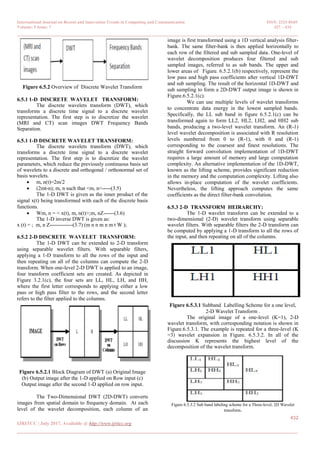
The 2-D sub band decomposition is just an
extension of 1-D sub band decomposition. The entire process
is carried out by executing 1-D sub band decomposition
twice, first in one direction (horizontal), then in the
orthogonal (vertical) direction. For example, the low-pass
sub bands (Li) resulting
from the horizontal direction is further decomposed in the
vertical direction, leading to LLi and LHi sub bands.
Similarly, the high pass sub band (Hi) is further decomposed
into HLi and HHi. After one level of transform, the image
can be further decomposed by applying the 2-D sub band
decomposition to the existing LLi sub band. This iterative
process results in multiple transform levels. In Figure. 6.5.3.2
the first level of transform results in LH1, HL1, and HH1, in
addition to LL1, which is further decomposed into LH2,
HL2, HH2, LL2 at the second level, and the information of
LL2 is used for the third level transform. The sub band LLi is
a low-resolution sub band and high-pass sub bands LHi, HLi,
HHi are horizontal, vertical, and diagonal sub band
respectively since they represent the horizontal, vertical, and
diagonal residual information of the original image. To
obtain a two-dimensional wavelet transform, the one-
dimensional transform is applied first along the rows and
then along the columns to produce four sub bands: low-
resolution, horizontal, vertical, and diagonal. (The vertical
sub band is created by applying a horizontal high-pass, which
yields vertical edges.) At each level, the wavelet transform
can be reapplied to the low-resolution sub band to further
decorrelate the image. Defining level and sub band
conventions used in the AWIC algorithm. The final
configuration contains a small low-resolution sub band. In
addition to the various transform levels, the phrase level 0 is
used to refer to the original image data.
6.6 Inverse DWT (IDWT):
DWT is used to separate the input low contrast
satellite image into different frequency sub bands, where the
LL sub band concentrates the illumination information. That
is why only the LL sub band goes through the process, which
preserves the high-frequency components (i.e., edges).
Hence, after inverse DWT (IDWT), the resultant image will
be sharper with good contrast.
Figure 6.6 Overview of IDWT
6.7 Fusion:
Image fusion is a data fusion technology which
keeps images as main research contents. It refers to the
techniques that integrate multi-images of the same scene
from multiple image sensor data or integrate multi images of
the same scene at different times from one image sensor.
The image fusion algorithm based on Wavelet Transform
which faster developed was a multi-resolution analysis
image fusion method in recent decade.
VII. CONCLUSION:
7.1 SUMMARY:
Image fusion is the process of combining relevant
information from minimum two images into a solo image.
The aim of this algorithm is that the resulting image will be
more informative than the source image and also relay on
the performance of the image after fusion. From the above
papers surveyed, most of the papers focuses on improving
the quality of the resultant image.
7.2 FUTURE ENHANCEMENTS:
We have proposed a system of Image Fusion
technique of DWT and the size of image which is going to
be fused can be increased .Since our technique focus on the
pixel range of 256x256.In future the pixel value can be
increase to have image fusion of pixel greater than
256x256.
REFERENCE
[1] Wang, Zhou. and Bovik,C Alan. ‖A universal image
quality index.‖ IEEE Signal Processing Letters, 9 (2002):
81-84.
[2] Wang, Zhou. , Bovik,C Alan. and Hamid, Rahim Sheikh.
―Image quality assessment :from error visibility to
structural similarity.‖ IEEE Transaction on Image
Processing , 13.4 (2004):600-612.
[3] Li,Shutao. ,KwoK,Tin-yau James. ,Tsang,Wai-Hung
Ivor. and Wang,Yaonan. ―Fusing images with different
focuses using vector machines.‖ IEEE Transaction On
Neural Network, 15.6 (2004):1555-1561.
[4] Tessens,Linda. ,Ledda,Alessandro. ,Zuricat,Pi
Aleksandra. And Philips,Wilfried. ―Extending the depth
of field in microscopy through curvelet-based frequency-
adaptive image fusion.‖ IEEE International Conference, 1
(2007): l-861 – l-864.
[5] Looney,David. And Danilo,P Mandic.‖MultiScale image
Fusion Using Complex Extension of EMD.‖ IEEE
Transaction On Signal Processing, 57.4 (2009):1626-
1630.
[6] Mrityunjay,kumar. and sarat,Dass. ―A total variation-
based algorithm for pixel-level image fusion.‖ IEEE
Transaction on Image processing, 18.9 ( 2009):2137-
2143.
[7] Li,Shutao. ,KwoK,Tin-yau James. and Wang,Yaonan.
―Combination of images with diverse focuses using the
Spatial Frequency.‖ Information Fusion, 2.3 (2001):169-
176(8).
[8] Li,Shutao. and Yang,Bin. ―Multifocus image fusion
using region segmentation and spatial frequency.‖ Image
and vision computing, 26.7 (2008):971-979.
[9] Wallance,G.k. ―The JPEG still picture compression
standard.‖ ,IEEE Transaction, 38.1 (1992):xvii-xxxiv.
[10] Nirmal, D.E. ,Vignesh, R.K. and Vaidehi,V.
―Multimodal image fusion in visual sensor networks.‖
IEEE International Conference on Electronics
,Computing and communication Technology, (2013):1-6.
[11] Piella,G. and Heijmans,H. ―A new quality metric for
image fusion.‖ International conference on image
processing, 3 (2003):III-173-6
8. International Journal on Recent and Innovation Trends in Computing and Communication ISSN: 2321-8169
Volume: 5 Issue: 7 427 – 434
_______________________________________________________________________________________________
434
IJRITCC | July 2017, Available @ http://www.ijritcc.org
_______________________________________________________________________________________
[12] Haghighat,A.B.M. ,Aghagolzadeh,Ali. and
seyedarabi,Hadi. ―A non-refeernce image fusion based
on mutual information of image features.‖ International
conference on computer and electrical engineering, 37.5
(2011):744-756. 52
[13] Kumar,B.K.S. ,Swamy,M.N.S. and Ahmad,M.O.
―Multiresolution DCT decomposition for multifocus
image fusion.‖ Annual IEEE candidate conference on
Electrical and computer Engineering, (2013):1-4.
[14] Malhotra,G.and chopra,vinay. ―A review on various
image fusion technique.‖ International journal of
computer engineering and application ,6.3 (2014).
[15] Yang,L. ,Guo,B.L. and Ni,W. ‖ Multimodality medical
image fusion based on multiscale geometric analysis of
contourlet transform .‖ Neurocomputing ,72.1-3
(2008):203-211.
[16] Amolins,krista. , Zhang,Yun. and Dare,peter. ―Wavelet
based image fusion techniques — An introduction,
review and comparison.‖ ISPRS Journal of
Photogrammetry and remote, 62.4 (2007):249-263.
[17] Zheng,Yufeng. , Essock,A.Edward and Hansen,c. ― An
Advanced Image Fusion Algorithm Based on Wavelet
Transform – Incorporation with PCA and Morphological
Processing .
[18] Guanqun,Tao. , Dapeng, Li. and Guanghua, Lu.
―Fusion based on different fusion rules of wavelet.
[19] Garzelli.‖ Wavelet based fusion of optical and SAR
image data over urban area.
[20] Sadjiadi,Firooz. ―Comparative Image fusion Analysis.
[21] Blum,R.and Liu,Z,Multi-sensor Image Fusion and its
applications London,CRC press,2005.