Downloaded 20 times

![T Jagan Mohan Rao Int. Journal of Engineering Research and Applications www.ijera.com
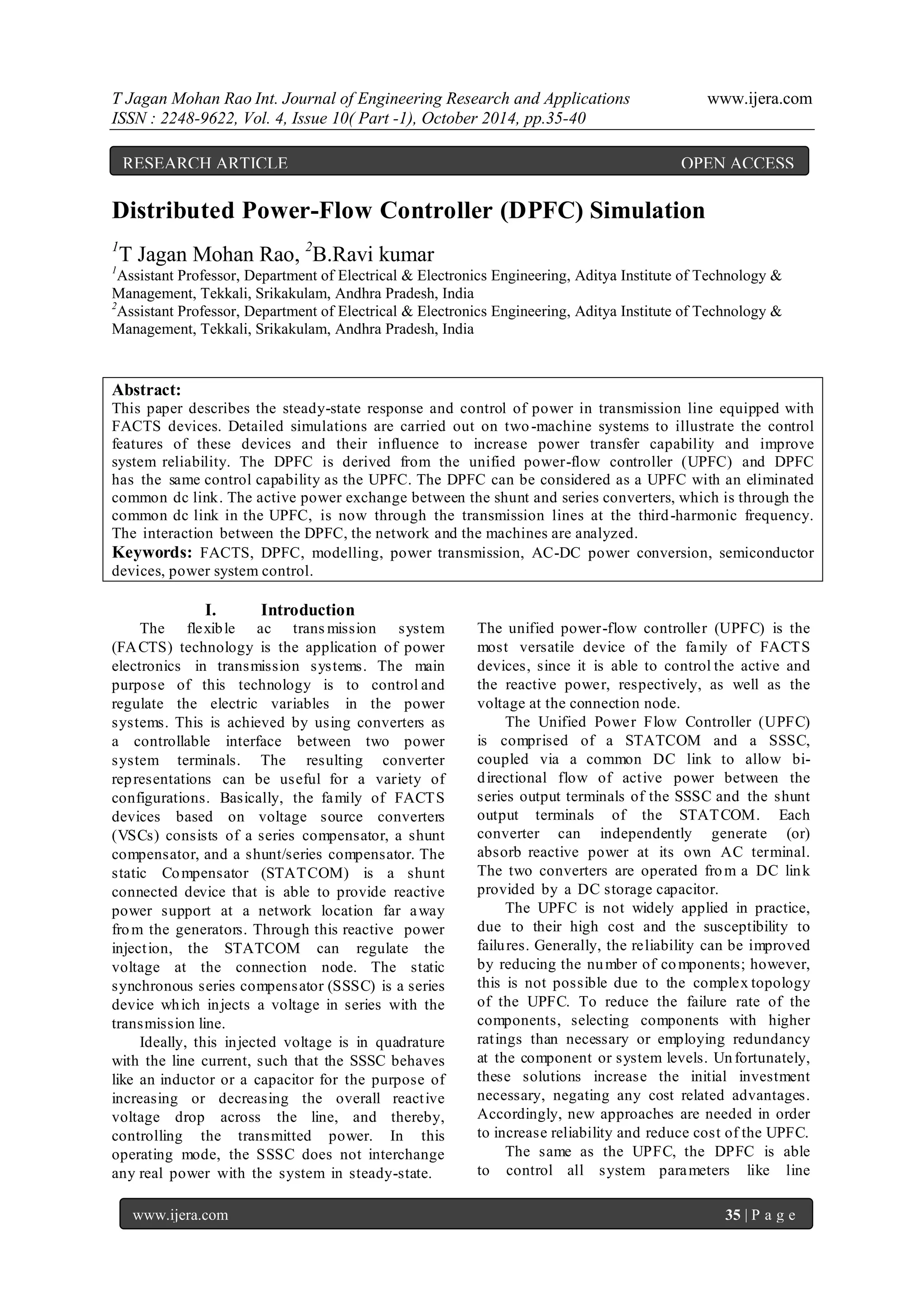
ISSN : 2248-9622, Vol. 4, Issue 10( Part -1), October 2014, pp.35-40
www.ijera.com 40 | P a g e
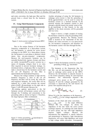
Fig. 13. Step response of the DPFC: line current.
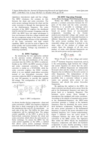
Fig. 14. Step response of the DPFC: active and
reactivse power injected by the series converter at
the fundamental frequency.
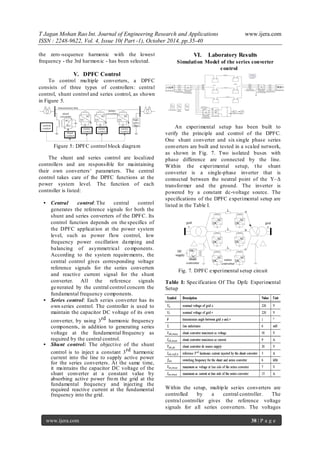
Fig. 15. Step response of the DPFC: bus voltage
and current at the Δ side of the transformer.
Conclusion
This paper has presented a new concept called
DPFC. The DPFC emerges from the UPFC and
inherits the control capability of the UPFC,
which is the simultaneous adjustment of the
line impedance, the transmission angle, and the
bus-voltage magnitude. The common dc link
between the shunt and series converters, which
is used for exchanging active power in the
UPFC, is eliminated. This power is now
transmitted through the transmission line at the
third-harmonic frequency. The series converter
of the DPFC employs the D-FACTS concept,
which uses multiple s mall single-phase
converters instead of one large-size converter.
The reliability of the DPFC is greatly increased
because of the redundancy of the series
converters. The total cost of the DPFC is also
much lower than the UPFC, because no high-
voltage isolation is required at the series-converter
part and the rating of the components of is low.
The DPFC concept has been verified by an
experimental setup. It is proved that the shunt and
series converters in the DPFC can exchange
active power at the third-harmonic frequency, and
the series converters are able to inject controllable
active and reactive power at the
fundamental frequency.
References
[1] Y.-H. Song and A. Johns, Flexible ac
Transmission Systems (FACTS) (IEE Power
and Energy Series), vol. 30. London, U.K.:
Institution of Electrical Engineers, 1999.
[2] N. G. Hingorani and L. Gyugyi,
Understanding FACTS: Concepts and
Technology of Flexible AC Transmission
Systems. New York: IEEEPress, 2000.
[3] L.Gyugyi, C.D. Schauder, S. L.Williams, T.
R. Rietman,D. R. Torgerson, And A. Edris,
―The unified power flow controller: A new
approach to power transmission control,‖
IEEE Trans.Power Del., vol. 10, no. 2, pp.
1085– 1097, Apr. 1995.
[4] A.-A. Edris, ―Proposed terms and definitions
for flexible ac transmission system (facts),‖
IEEE Trans. Power Del., vol. 12, no. 4, pp.
1848–1853, Oct. 1997.](https://image.slidesharecdn.com/f41003540-141115040119-conversion-gate01/85/Distributed-Power-Flow-Controller-DPFC-Simulation-6-320.jpg)

This document describes simulations carried out on Distributed Power-Flow Controller (DPFC) technology. Key points: - DPFC is derived from Unified Power Flow Controller (UPFC) but eliminates the common DC link between shunt and series converters. Active power is exchanged through the transmission line using third-harmonic frequency components. - DPFC has advantages over UPFC of lower cost due to lower component ratings/isolation for series converter, and higher reliability due to redundancy of series converters. - Detailed simulations were performed on a two-machine system to illustrate DPFC's control features and ability to increase power transfer capability and improve system reliability compared to conventional systems. Laboratory tests validated the DPFC operating principle and