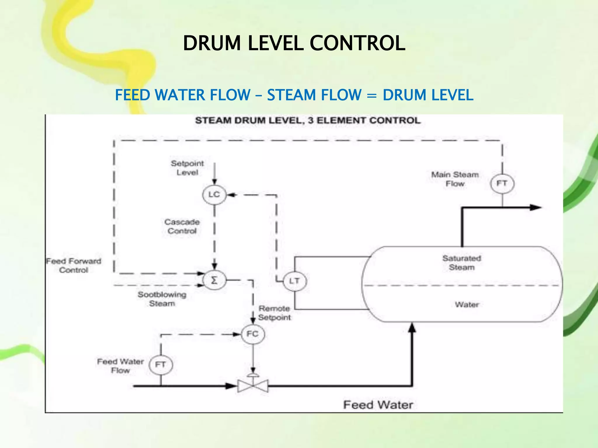
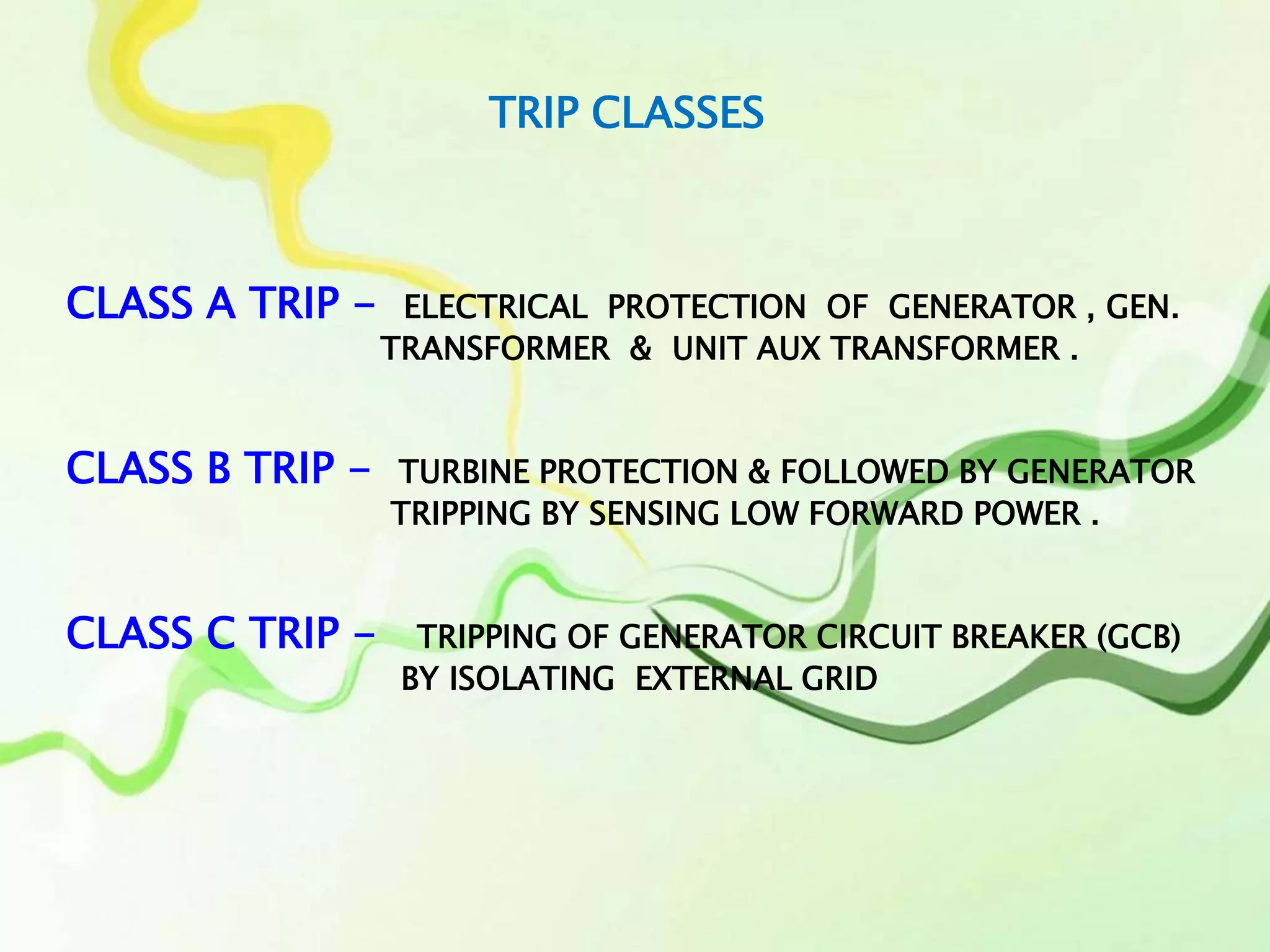
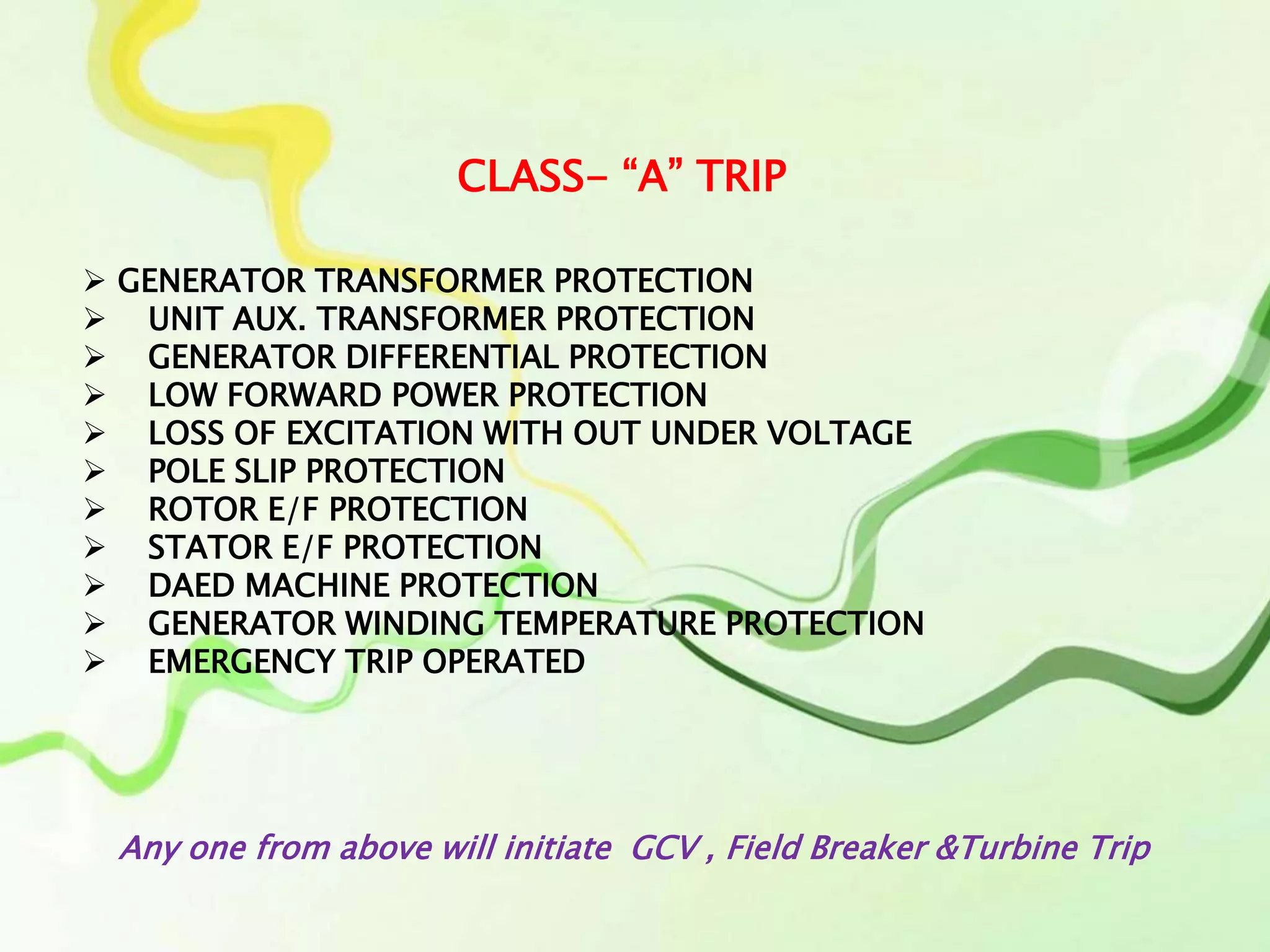
Power Plant Process
&
It’s
Instrumentation - Control
BY – D. CHAKRABORTY
C & I Dept
BOILER CONTROLS
1. DRUM level Control
2. Main Steam Temp Control
3. Furnace Draft Control
4. APH Outlet Temperature Control
DRUM LEVEL CONTROL
FEED WATER FLOW – STEAM FLOW = DRUM LEVEL
The changes in steam flow can also cause large deviations in drum level,
and could possibly trip the boiler. Changes in steam flow rate are
measurable and this measurement can be used to improve level control
very successfully by using a feed forward control strategy.
For the feed forward control strategy, steam flow rate is measured and
used as the set point of the feed water flow controller. In this way the feed
water flow rate is adjusted to match the steam flow. Changes in steam flow
rate will almost immediately be counteracted by similar changes in feed
water flow rate. To ensure that deviations in drum level are also used for
control, the output of the drum level controller is added to the feed
forward from steam flow.
The combination of drum level measurement, steam flow measurement,
and feed flow measurement to control boiler drum level is called three-
element control.
Turbine Loops
1. Hot well level Control
2. D/A Level Control
3. Aux PRDS Lev Control
4. Gland Steam Pressure Control
HOTWELL LEVEL CONTROL
The steam after passing through low pressure turbine it goes to the
condenser . In the condenser, the steam is turned in to water. Upon
passing the turbine, the steam density, temperature and pressure get
reduced.
Hence, to suck the steam, a vacuum pressure is applied on steam by
the condenser. Then the steam reaches the condenser and touches the
water tubes which are carrying cool water from cooling towers and then
the steam condensates in to the water and the water is collected at the
bottom of the condenser. Here, the temperature of the water in the
condenser will be approximately 30 to 40 degree Celsius. Hence,
condenser is commonly called as HOT WELL.
The hot well level is to be maintained to normal level. This is why
because, if the water level in the hot well goes below the desired
level, the vacuum level increases so that the low pressure turbine
blades gets sucked along with the steam by the vacuum pressure
and if the water level in the condenser raises above the desired
level, then deterioration of vacuum takes place.
Hence, the water level in the hot well should be maintained to a
fixed level. Thus undesired water level in the hot well effects power
plant efficiency.
.
TRIP CLASSES
CLASS A TRIP - ELECTRICAL PROTECTION OF GENERATOR , GEN.
TRANSFORMER & UNIT AUX TRANSFORMER .
CLASS B TRIP - TURBINE PROTECTION & FOLLOWED BY GENERATOR
TRIPPING BY SENSING LOW FORWARD POWER .
CLASS C TRIP - TRIPPING OF GENERATOR CIRCUIT BREAKER (GCB)
BY ISOLATING EXTERNAL GRID
 GENERATOR TRANSFORMER PROTECTION
 UNIT AUX. TRANSFORMER PROTECTION
 GENERATOR DIFFERENTIAL PROTECTION
 LOW FORWARD POWER PROTECTION
 LOSS OF EXCITATION WITH OUT UNDER VOLTAGE
 POLE SLIP PROTECTION
 ROTOR E/F PROTECTION
 STATOR E/F PROTECTION
 DAED MACHINE PROTECTION
 GENERATOR WINDING TEMPERATURE PROTECTION
 EMERGENCY TRIP OPERATED
CLASS- “A” TRIP
Any one from above will initiate GCV , Field Breaker &Turbine Trip
CLASS – “B” TRIP
 UNDER FREQUENCY PROTECTION
 OVER FREQUENCY PROTECTION
 LOSS OF EXCITATION WITH UNDER VOLTAGE
 CLASS – A TRIP
 E.P.B. OPERATED FROM WWG
 TRIP SIGNAL GENERATED FROM TURBINE PROTECTION
Any one from above will initiate Turbine Trip
 NEG. PH. SEQ. PROTECTION
 REVERSE POWER PROTECTION
 OVER VOLTAGE PROTECTION
 OVER FLUX PROTECTION
 GT OIL TEMP. HIGH
 UAT OIL TEMP. HIGH
CLASS- “C” TRIP
Any one from above will initiate GCB & UAT –LV BREAKER
Power Plant Instrumentation & Control

Power Plant Instrumentation & Control

  • 1.
    Power Plant Process & It’s Instrumentation- Control BY – D. CHAKRABORTY C & I Dept
  • 2.
    BOILER CONTROLS 1. DRUMlevel Control 2. Main Steam Temp Control 3. Furnace Draft Control 4. APH Outlet Temperature Control
  • 3.
    DRUM LEVEL CONTROL FEEDWATER FLOW – STEAM FLOW = DRUM LEVEL
  • 4.
    The changes insteam flow can also cause large deviations in drum level, and could possibly trip the boiler. Changes in steam flow rate are measurable and this measurement can be used to improve level control very successfully by using a feed forward control strategy. For the feed forward control strategy, steam flow rate is measured and used as the set point of the feed water flow controller. In this way the feed water flow rate is adjusted to match the steam flow. Changes in steam flow rate will almost immediately be counteracted by similar changes in feed water flow rate. To ensure that deviations in drum level are also used for control, the output of the drum level controller is added to the feed forward from steam flow. The combination of drum level measurement, steam flow measurement, and feed flow measurement to control boiler drum level is called three- element control.
  • 5.
    Turbine Loops 1. Hotwell level Control 2. D/A Level Control 3. Aux PRDS Lev Control 4. Gland Steam Pressure Control
  • 6.
  • 7.
    The steam afterpassing through low pressure turbine it goes to the condenser . In the condenser, the steam is turned in to water. Upon passing the turbine, the steam density, temperature and pressure get reduced. Hence, to suck the steam, a vacuum pressure is applied on steam by the condenser. Then the steam reaches the condenser and touches the water tubes which are carrying cool water from cooling towers and then the steam condensates in to the water and the water is collected at the bottom of the condenser. Here, the temperature of the water in the condenser will be approximately 30 to 40 degree Celsius. Hence, condenser is commonly called as HOT WELL.
  • 8.
    The hot welllevel is to be maintained to normal level. This is why because, if the water level in the hot well goes below the desired level, the vacuum level increases so that the low pressure turbine blades gets sucked along with the steam by the vacuum pressure and if the water level in the condenser raises above the desired level, then deterioration of vacuum takes place. Hence, the water level in the hot well should be maintained to a fixed level. Thus undesired water level in the hot well effects power plant efficiency. .
  • 9.
    TRIP CLASSES CLASS ATRIP - ELECTRICAL PROTECTION OF GENERATOR , GEN. TRANSFORMER & UNIT AUX TRANSFORMER . CLASS B TRIP - TURBINE PROTECTION & FOLLOWED BY GENERATOR TRIPPING BY SENSING LOW FORWARD POWER . CLASS C TRIP - TRIPPING OF GENERATOR CIRCUIT BREAKER (GCB) BY ISOLATING EXTERNAL GRID
  • 10.
     GENERATOR TRANSFORMERPROTECTION  UNIT AUX. TRANSFORMER PROTECTION  GENERATOR DIFFERENTIAL PROTECTION  LOW FORWARD POWER PROTECTION  LOSS OF EXCITATION WITH OUT UNDER VOLTAGE  POLE SLIP PROTECTION  ROTOR E/F PROTECTION  STATOR E/F PROTECTION  DAED MACHINE PROTECTION  GENERATOR WINDING TEMPERATURE PROTECTION  EMERGENCY TRIP OPERATED CLASS- “A” TRIP Any one from above will initiate GCV , Field Breaker &Turbine Trip
  • 11.
    CLASS – “B”TRIP  UNDER FREQUENCY PROTECTION  OVER FREQUENCY PROTECTION  LOSS OF EXCITATION WITH UNDER VOLTAGE  CLASS – A TRIP  E.P.B. OPERATED FROM WWG  TRIP SIGNAL GENERATED FROM TURBINE PROTECTION Any one from above will initiate Turbine Trip
  • 12.
     NEG. PH.SEQ. PROTECTION  REVERSE POWER PROTECTION  OVER VOLTAGE PROTECTION  OVER FLUX PROTECTION  GT OIL TEMP. HIGH  UAT OIL TEMP. HIGH CLASS- “C” TRIP Any one from above will initiate GCB & UAT –LV BREAKER

Editor's Notes

  • #2 Debyendu Chakraborty – I & C , Power Plant , debyendu.chakroborty@rp-sg.in
  • #4 debyendu.chakroborty@rp-sg.in
  • #7 debyendu.chakroborty@rp-sg.in
  • #10 debyendu.chakroborty@rp-sg.in, 8420012600
  • #11 debyendu.chakroborty@rp-sg.in