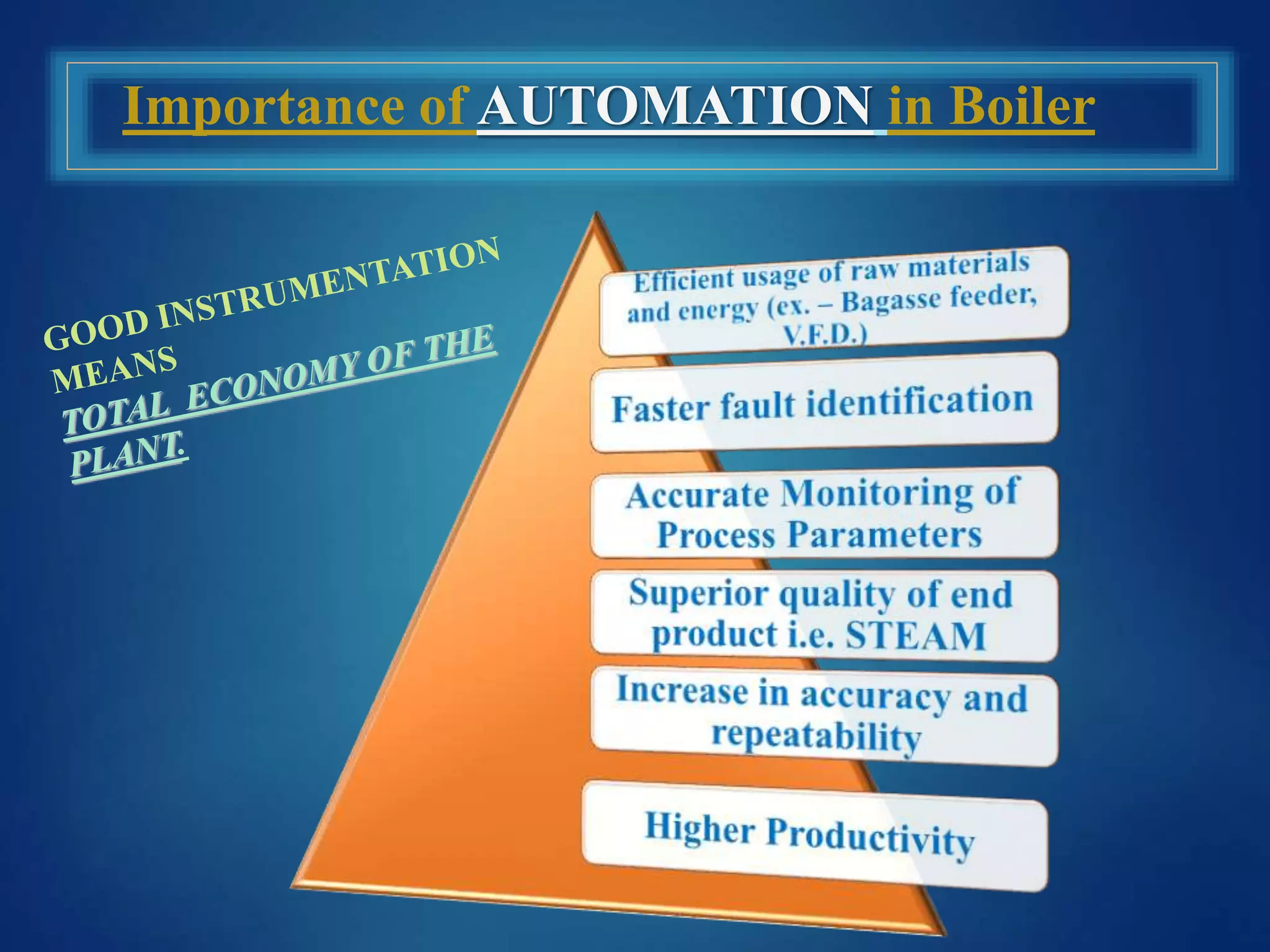
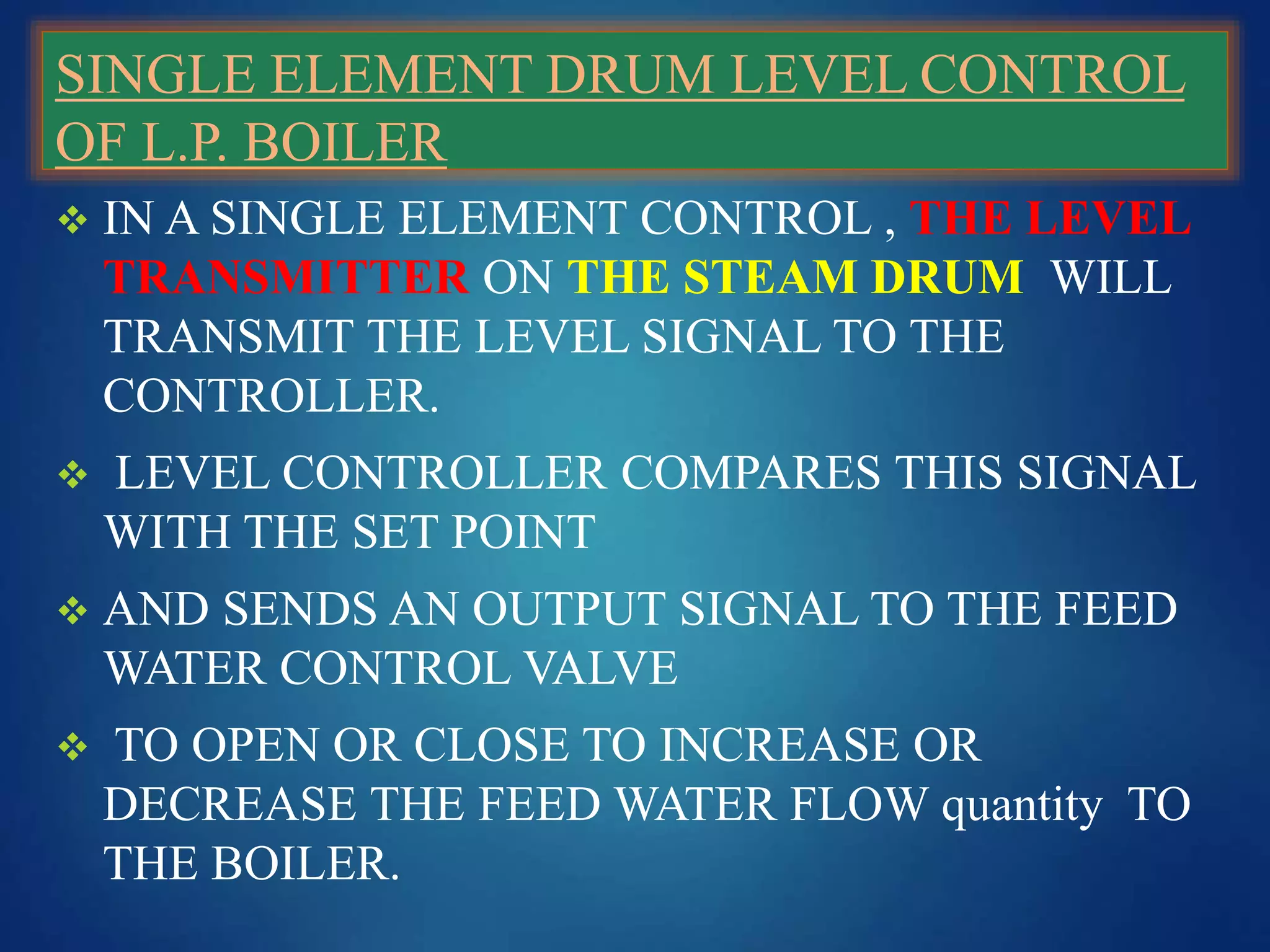
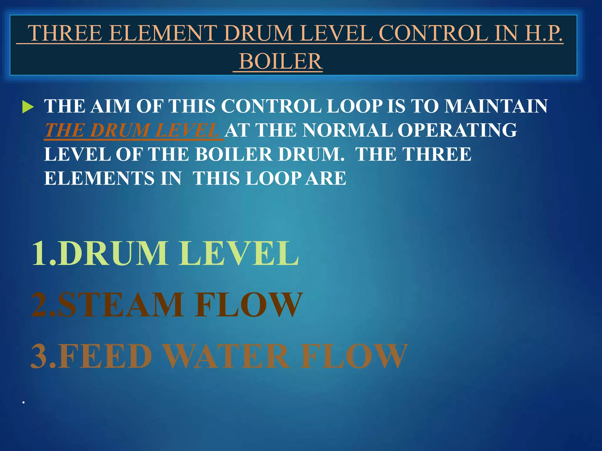
BOILER AUTOMATION
PRESENTED BY
AMAR GUPTA
Importance of AUTOMATION in Boiler
1. The controller we are using in the
boiler is ABB 800M Make Ethernet
based.
2. It is a comprehensive, distributed and
modular process I/O system that
communicates with parent controllers
over industry-standard field buses
3.. In our arrangement we have to two
system one is server and other redundant
PC of server (and can be access in case
of emergency)
Boiler Existing Control loop
 DRUM LEVEL (via 3 Element & Single Element)
 Combustion Control
 Deaerator Level
 Deaerator Pressure
 Furnace pressure control function
 P.R.D.S.H.
 S.H. STEAM TEMPERATURE
 BOILER INTERLOCKS
SINGLE ELEMENT DRUM LEVEL CONTROL
OF L.P. BOILER
 IN A SINGLE ELEMENT CONTROL , THE LEVEL
TRANSMITTER ON THE STEAM DRUM WILL
TRANSMIT THE LEVEL SIGNAL TO THE
CONTROLLER.
 LEVEL CONTROLLER COMPARES THIS SIGNAL
WITH THE SET POINT
 AND SENDS AN OUTPUT SIGNAL TO THE FEED
WATER CONTROL VALVE
 TO OPEN OR CLOSE TO INCREASE OR
DECREASE THE FEED WATER FLOW quantity TO
THE BOILER.
Steam Drum LT
LIC
I/P
Feed
Pump
Single element drum level control in LP Boiler
CONTROL VALVE
BY PASS VALVE
SET POINT
 In high pressure boilers , when the steam demand of the boiler increases
suddenly ,
 The withdrawal of steam from the steam drum will be higher than the
steam generation as combustion control will take some time to react and
increase the fuel heat input to the boiler.
 This will result in drum pressure falling temporarily, this loss of pressure
will result in the formation of steam bubbles in the drum water due to the
enthalpy difference between the two pressure levels.
 This bubbling in the drum water will result in the foaming and increase
in the volume leading to the level going up spuriously.
 The level transmitter will transmit this increase in drum level to the
controller leading to reduction in feed water flow instead of increasing
the feed water flow due to higher demand on boiler.
 To avoid such a wrong control 3 element drum level control is required
THREE ELEMENT DRUM LEVEL CONTROL IN H.P.
BOILER
 THE AIM OF THIS CONTROL LOOP IS TO MAINTAIN
THE DRUM LEVEL AT THE NORMAL OPERATING
LEVEL OF THE BOILER DRUM. THE THREE
ELEMENTS IN THIS LOOPARE
1.DRUM LEVEL
2.STEAM FLOW
3.FEED WATER FLOW
.
Three Element Loop Diagram
DEAERATOR LEVEL CONTROL LOOP
 The deaerator level control is similar
to the single element drum level
control.
DEAERATOR
TANK
D.C.S.
I/P
Two wire P.S..
FEED WATER
4 – 20 mA. AIR SIG.
WATER INLET
BY PASS VALVE
DEAERATOR PRESSURE CONTROL LOOP
DEAERATOR
TANK
P.T.
D.C.S.
I/P
TwowireP.S.
STEAM PRESSURE
0.2 - 0.5 KG/CM^2
 This is
necessary to
maintain the
de-aeration
temperature at
the required
to achieve the
removal of
gases from
water.
P.R.V.
Pressure
Transmitter
4 – 20 mA
WATER INLET
FEED
PUMP
AIR SIG.
 In boilers with high super heat
temperatures it is necessary to protect the
down stream equipment like steam
turbine from large variation in
temperatures.
 The steam temperature leaving the boiler
is required to be maintained constant in
many applications.
 The super heater outlet temperature is
sent to the controller by the temperature
transmitter.
 The controllers compares the same with
the set point and gives a resultant signal
to the spray control valve to change the
spray water quantity.
De-superheater
spray flow valve
TT
PV
MV
SP
+
-
-
Temperature
control
Water flow to de-superhtr.
Heat flow to
1st stage
+
Steam temp from
1st stage superhtr.
Heat flow to
2nd stage
2nd stage
superheate
r.
 In boilers provided with both FD
and id fans it is necessary to
maintain the furnace draft at near
zero pressure. ( between –5 to –10
mmwc to prevent flame from
coming out and injuring operating
personnel )
 The furnace draft transmitter sends
the furnace draft signal to the
controller.
 Controller on comparing the same
with the set point sends an output
signal to the V.F.D. of the id fan
and it control the speed and thus
controls the furnace pressure
within limits.
SP GIVEN BY
OPERATOR
Furnace
ID Fan
extraction
rate
Draft control
PT
PV
SP
+
-
-
+
FD air flow
Difference will integrate
to change pressure over
time
 The main object of automatic boiler combustion control is to
regulate automatically, the heat input to a boiler in terms of fuel and
air supplied in relation to output or steam demand.
 This should be implemented as efficiently as possible in terms of
combustion quality and furnace stability.
 Steam pressure is taken as the indication for boiler load as the
steam pressure decreases in increasing load and vice versa.
 Hence variations in steam pressure is detected and the supply of the
fuel and air adjusted accordingly.
 The successful operation of the combustion control system depends
upon the capability to vary the fuel supply to the furnace based on
the signals from the control system.
 The steam demand from boiler vary
depending upon change in process
requirement or power requirement.
 The fuel fed to the boiler should be
controlled to give the necessary quantity
of steam.
 The steam demand increase or decrease
will be indicated by the boiler outlet
pressure.
 Hence combustion control is essentially
a control to keep the boiler outlet
pressure constant.
 The steam pressure transmitter in the
main steam line sends the signal to the
controller which in turn sends an output
signal to the feeder motors in the solid
fuel fired boilers and to the fuel control
valve in the case of oil and gas fired
boilers.
Boiler master
controller
Fuel Air ratio
Air
controller
Fuel
controller
FD air
V.F.D.
Fuel
V.F.D.
Furnace
/Steam
PT
S.P.
S.P.
S.P.S.P.
Firing Rate
Demand
Pressure Reducing Desuper heating
 This control loop is very important for
process point of view in sugar industry
 Because the reaming amount of steam is
completed by this conversion in Boiling
House.
 In this live steam is enter of pressure
45Kg/cm^2 and temperature of 440-
445*C
 Now with the help of pressure reducing
valve and de-super heating valve this live
steam is converted into required demand
of Boiling House up to 1.5 Kg/cm^2 @
118 – 122 *C and one more PRDSH need
to install requirement of 7 Kg/cm^2 *C
steam for Sulphur Burner and Super
heated wash water.
 For continuous controlling of both
parameter we have a feedback loop of
Pressure transmitter and Temperature
transmitter
PT
TT
D.C.S
I/P
P.R.V.
Water Inlet
BY PASS VALVE
45 Kg/cm^2
1.5 or 7Kg/cm^2
Steam Inlet
410-425*C
118-125*C
BOILER INTERLOCKS
 In addition to closed loop fully modulating controls required for the
normal operation of the boiler , interlock controls are required for the
safe startup, shut-down and operation of the boiler.
 The following are some of the interlocks are being used for baggass fired
boilers.
 ID run feed back with FD fan.
 Fuel feeder will not start without FD and ID fans run.
 Fuel feeder trip in case of steam drum low level very low trip switch is
activated
 Boiler will trip if instrument air pressure fails.
 Standby feed pump will automatically come into operation when
operating pump fails (NOT EXISTING)
Boiler automation new

Boiler automation new

  • 1.
  • 2.
  • 3.
    1. The controllerwe are using in the boiler is ABB 800M Make Ethernet based. 2. It is a comprehensive, distributed and modular process I/O system that communicates with parent controllers over industry-standard field buses 3.. In our arrangement we have to two system one is server and other redundant PC of server (and can be access in case of emergency)
  • 4.
    Boiler Existing Controlloop  DRUM LEVEL (via 3 Element & Single Element)  Combustion Control  Deaerator Level  Deaerator Pressure  Furnace pressure control function  P.R.D.S.H.  S.H. STEAM TEMPERATURE  BOILER INTERLOCKS
  • 5.
    SINGLE ELEMENT DRUMLEVEL CONTROL OF L.P. BOILER  IN A SINGLE ELEMENT CONTROL , THE LEVEL TRANSMITTER ON THE STEAM DRUM WILL TRANSMIT THE LEVEL SIGNAL TO THE CONTROLLER.  LEVEL CONTROLLER COMPARES THIS SIGNAL WITH THE SET POINT  AND SENDS AN OUTPUT SIGNAL TO THE FEED WATER CONTROL VALVE  TO OPEN OR CLOSE TO INCREASE OR DECREASE THE FEED WATER FLOW quantity TO THE BOILER.
  • 6.
    Steam Drum LT LIC I/P Feed Pump Singleelement drum level control in LP Boiler CONTROL VALVE BY PASS VALVE SET POINT
  • 7.
     In highpressure boilers , when the steam demand of the boiler increases suddenly ,  The withdrawal of steam from the steam drum will be higher than the steam generation as combustion control will take some time to react and increase the fuel heat input to the boiler.  This will result in drum pressure falling temporarily, this loss of pressure will result in the formation of steam bubbles in the drum water due to the enthalpy difference between the two pressure levels.  This bubbling in the drum water will result in the foaming and increase in the volume leading to the level going up spuriously.  The level transmitter will transmit this increase in drum level to the controller leading to reduction in feed water flow instead of increasing the feed water flow due to higher demand on boiler.  To avoid such a wrong control 3 element drum level control is required
  • 8.
    THREE ELEMENT DRUMLEVEL CONTROL IN H.P. BOILER  THE AIM OF THIS CONTROL LOOP IS TO MAINTAIN THE DRUM LEVEL AT THE NORMAL OPERATING LEVEL OF THE BOILER DRUM. THE THREE ELEMENTS IN THIS LOOPARE 1.DRUM LEVEL 2.STEAM FLOW 3.FEED WATER FLOW .
  • 9.
  • 10.
    DEAERATOR LEVEL CONTROLLOOP  The deaerator level control is similar to the single element drum level control. DEAERATOR TANK D.C.S. I/P Two wire P.S.. FEED WATER 4 – 20 mA. AIR SIG. WATER INLET BY PASS VALVE
  • 11.
    DEAERATOR PRESSURE CONTROLLOOP DEAERATOR TANK P.T. D.C.S. I/P TwowireP.S. STEAM PRESSURE 0.2 - 0.5 KG/CM^2  This is necessary to maintain the de-aeration temperature at the required to achieve the removal of gases from water. P.R.V. Pressure Transmitter 4 – 20 mA WATER INLET FEED PUMP AIR SIG.
  • 12.
     In boilerswith high super heat temperatures it is necessary to protect the down stream equipment like steam turbine from large variation in temperatures.  The steam temperature leaving the boiler is required to be maintained constant in many applications.  The super heater outlet temperature is sent to the controller by the temperature transmitter.  The controllers compares the same with the set point and gives a resultant signal to the spray control valve to change the spray water quantity. De-superheater spray flow valve TT PV MV SP + - - Temperature control Water flow to de-superhtr. Heat flow to 1st stage + Steam temp from 1st stage superhtr. Heat flow to 2nd stage 2nd stage superheate r.
  • 13.
     In boilersprovided with both FD and id fans it is necessary to maintain the furnace draft at near zero pressure. ( between –5 to –10 mmwc to prevent flame from coming out and injuring operating personnel )  The furnace draft transmitter sends the furnace draft signal to the controller.  Controller on comparing the same with the set point sends an output signal to the V.F.D. of the id fan and it control the speed and thus controls the furnace pressure within limits. SP GIVEN BY OPERATOR Furnace ID Fan extraction rate Draft control PT PV SP + - - + FD air flow Difference will integrate to change pressure over time
  • 14.
     The mainobject of automatic boiler combustion control is to regulate automatically, the heat input to a boiler in terms of fuel and air supplied in relation to output or steam demand.  This should be implemented as efficiently as possible in terms of combustion quality and furnace stability.  Steam pressure is taken as the indication for boiler load as the steam pressure decreases in increasing load and vice versa.  Hence variations in steam pressure is detected and the supply of the fuel and air adjusted accordingly.  The successful operation of the combustion control system depends upon the capability to vary the fuel supply to the furnace based on the signals from the control system.
  • 15.
     The steamdemand from boiler vary depending upon change in process requirement or power requirement.  The fuel fed to the boiler should be controlled to give the necessary quantity of steam.  The steam demand increase or decrease will be indicated by the boiler outlet pressure.  Hence combustion control is essentially a control to keep the boiler outlet pressure constant.  The steam pressure transmitter in the main steam line sends the signal to the controller which in turn sends an output signal to the feeder motors in the solid fuel fired boilers and to the fuel control valve in the case of oil and gas fired boilers. Boiler master controller Fuel Air ratio Air controller Fuel controller FD air V.F.D. Fuel V.F.D. Furnace /Steam PT S.P. S.P. S.P.S.P. Firing Rate Demand
  • 16.
    Pressure Reducing Desuperheating  This control loop is very important for process point of view in sugar industry  Because the reaming amount of steam is completed by this conversion in Boiling House.  In this live steam is enter of pressure 45Kg/cm^2 and temperature of 440- 445*C  Now with the help of pressure reducing valve and de-super heating valve this live steam is converted into required demand of Boiling House up to 1.5 Kg/cm^2 @ 118 – 122 *C and one more PRDSH need to install requirement of 7 Kg/cm^2 *C steam for Sulphur Burner and Super heated wash water.  For continuous controlling of both parameter we have a feedback loop of Pressure transmitter and Temperature transmitter PT TT D.C.S I/P P.R.V. Water Inlet BY PASS VALVE 45 Kg/cm^2 1.5 or 7Kg/cm^2 Steam Inlet 410-425*C 118-125*C
  • 17.
    BOILER INTERLOCKS  Inaddition to closed loop fully modulating controls required for the normal operation of the boiler , interlock controls are required for the safe startup, shut-down and operation of the boiler.  The following are some of the interlocks are being used for baggass fired boilers.  ID run feed back with FD fan.  Fuel feeder will not start without FD and ID fans run.  Fuel feeder trip in case of steam drum low level very low trip switch is activated  Boiler will trip if instrument air pressure fails.  Standby feed pump will automatically come into operation when operating pump fails (NOT EXISTING)