1. A Systematic Approach to Develop PLC Program
for Automation of a Glass Handling Gantry
System in Automobile Industry
Saruk Ajit Suresh
Postgraduate scholar
M.Tech. Mechatronics
VIT University,
Chennai, India
Email- ajitsaruk88888@gmail.com
Dr. G. Sakthivel
M.Tech. Mechatronics
VIT University,
Chennai, India
Email- sakthivel.g@vit.ac.in
Abstract-In industries most of the time gantry system
is used for the pick and place operation in inline loop. In this
work the gantry system is modified slightly. Gantry system is
used to assemble the front glass of the automobile. Three axis
movements are given to the one single gantry to accomplish the
required task. For the movement of the gantry rack and pinion
arrangement is used.
Automation in automotive assembly line would
be useful for safety and large production. Automotive
industry continuously strive to find better ways to
increase output, improve quality and uphold the highest
safety standards while decreasing cost. In this project
work programmable logic controller (PLC) is used for
the key activities of automatic glass assembly system and
will focus on the improving the position accuracy by the
use of combination of the encoder, limit switches and
barcode reader. The feedback from these three sensors is
given back to the PLC to control the speed of the servo motor.
Keywords-gantry; PLC; barcode scanner;
encoder; limit switch (LS).
I. INTRODUCTION
In automobile industry the front glass of the
vehicle is a very crucial and delicate part. This part should
be carry with essential attention. Here automation is done to
assemble front glass to the vehicle body. This is achieved
with slight modification in gantry system and with the help
of PLC programming. This system has proposed with three
axis through which the gantry system move. This movement
can be achieved by rack and pinion. Considering position
accuracy as prime consideration in this work the servo
motor has been selected. Achieving positional accuracy at
high level is the main task. The positional accuracy can be
achieved with limit switch, encoder and barcode reader.
Most of the industry uses limit switch and encoder to
achieve the position accuracy.
In this kind of application the position of the gantry
system will be known by using hard and soft feedback. Hard
feedback can be achieved by the limit switch and soft
feedback can be achieved by using encoder. But most of the
time break downs like over travel or under travel can occur.
For minimizing probability and frequencies of such kind of
breakdowns in addition to limit switch and encoder, barcode
scanner system is used. Barcode is located throughout the
rack of the gantry. This bar code is then scan by the laser
barcode scanner. The signals of the limit switch, barcode
scanner and encoder used to communicate with PLC and the
PLC generates the corresponding signal through which the
movements of the motors can be controlled in efficient way.
The proximity sensors are used for the sensing of
the part. Ball and lever type limit switches are used to limit
the movement of the gantry. As the part to be lifted is very
delicate, vacuum cups are used.
II. MECHANICAL AND ELECTRONICS
STRUCRURE
The rack and pinion arrangement is used for the
transmission of the gantry. Three servo motors are used to
achieve the desired location. Each servo motor is designed
for the capacity of 2 KW. Servo motors are connected to the
gearbox to bring down the motor speed to the required
speed. The gearbox is designed in such a way that the gear
ratio can fulfils the desired speed conditions. The front glass
of the automobile is very mild in characteristics so using
mechanical gripper may harm the glass. To handle the front
glass of automobile without damaging it, vacuum cups are
used. The pneumatic circuit is used for operating the
vacuum grippers. In the pneumatic circuit the direction
control valves are operated by the solenoid and solenoid is
operated by the PLC.
Latch is used for controlling and supporting the
vertical up and down movement of the gantry. Latch is
operated by the solenoid. Servo motors are fixed on the
gantry. It is very necessary to travel the servo motor with
gantry. The connection to servo motor is given by the
flexible cable which may suitable to operate at highly
dynamic condition.
The fixture is designed in such a way that while
picking up the glass there would not be any angular motion
to the gripper. This brings the mechanical stability in
operation. The gripper just need to go pick up position and
then it can picked up the glass.
2. Fig. (a) shows the mechanism needed for the
movement of the gantry and for achieving the desired
position. Fig. (b) shows the enlarged gripper structure.
Fig. (a) Internal mechanism for the movement of the gantry
system
Fig. (b) Gripper gantry system
The electronics parts such as proximity sensors, limit
switches, encoder, and servo drive are controlled by the
PLC. Servo drive is used to control the speed of servo motor
by varying the frequency. Frequency and speed are directly
proportional. The sensors signals are gathered in the
junction box and then only one cable has been taken out and
connected to the remote I/O. From remote I/O the Ethernet
cable is used to communicate with PLC.
III. CONCEPT OF CONTROLLING A SYSTEM
The concept of controlling a system involves the
following steps
A. Sequence of Operation
In this step, identification of the equipment and its
working plays a vital role. The main purpose of using PLC
controller is to control the external system. In PLC logical
conditions are given and PLC produces the output according
to these given conditions. The output of the PLC is given to
the controlling parameters which controls the movement of
the gantry. To achieve this one need to develop the
sequence of operation and understand detailed operation.
Initially the gantry is at home position. Two part
present proximity sensors are used at conveyor to let PLC
knows that the body is present at the conveyor. And another
two capacitive type proximity sensors are used to sense the
presence of the front glass of the automobile. When these
four proximity sensors signals are true then the operation
can be started. Three servo motors are used to guide the
gantry in X, Y and Z direction. Let the name to each motor
is given as X-Motor, Y-Motor and Z-Motor. When the start
signal is given by the PLC then the Z-Motor is started and
helped the gantry to move down. Then the solenoid is
operated and the vacuum cups come into operation. Vacuum
cups hold the glass with the help of four capacitive
proximity sensors located at near to the each vacuum cup
and then Z-Motor used to lift the gantry. After wards the Y-
Motor starts running and bring the gripper above the
conveyor. The position of the gantry at this position is set
already. Then the X-Motor start moving and helps to bring
the gantry at parking position. Parking position is sensed by
the parking ball type limit switch. Anti-collision sensor is
used to avoid the collision of the gantry with the
automobile. The range of anti-collision sensor is adjusted at
minimum level in such a way that it will not create any
problem while assembling with the automobile. Two
proximity sensors are used of different ranges. When the
gantry is at parking position the automobile body will start
moving towards the gantry. When the proximity sensors
used for getting feedback of assembly operation is done, are
activated then that signal is used for releasing the glass.
Maximum travel distance limit switch is used to set the
maximum distance at which the gantry can move. Then X-
Motor starts moving fast to maintain a safe distance
between automobile and gantry. After that X-Motor stop
and Z-Motor starts running to move the gantry up. Then
again the X-Motor starts running to bring the gantry towards
home position. Y-Motor starts running to move the gripper
away from the conveyor. And the gantry system is parked at
the home position. Home position limit switch is used to get
the feedback of the gantry position at home position.
3. B. Assignment of Inputs and Outputs
Devices connected as input and output must have
specific ferrule number. The input devices that are
connected to input module of PLC are
1) Proximity sensors
2) Limit switches
3) Encoders
4) Barcode scanner
The output devices that are connected to the output module
of the PLC are
1) Servo motors
2) Latches
3) Solenoids
Before start writing the actual ladder PLC program the
wire numbers should be given because after that only PLC
could trigger the require output. So assigning input and
output wire number is important.
C. Develop Timing Diagram
The clear understanding of the process is
understood by the timing diagram. Timing diagram is
shown in the Fig. (e).
D. Develop Flow Chart
Flow chart is drawn considering the sequence of
operations of control process. Fig. (c) shows the flow chart
of sequence of operation.
E. Writing of the program
While writing the program attention is paid to the
following steps
• Task requirements.
• Software design techniques.
• Documentation.
• Program testing.
IV. POSITION ACCURACY
Achieving the position accuracy at high level is the
necessity of this work. For achieving this accuracy the
combination of limit switch, encoder and barcode reader is
used.
A. Encoders-
Encoder modules interface encoder device with
programmable controllers. This type of module operates
independently of the processor and I/O scan. An encoder
module is an integral part of a programmable controller
system when it is used in applications requiring position
information. Absolute encoder and incremental encoder are
the type of encoders in this work incremental encoder is
used. This encoder has two signals for one rotation with 900
phase difference; it then determines the direction of rotation
by sensing the leading waveform. These pulses are then
count in marker, and marker gives these pulses as input to
the input module.
In PLC program counter block is used which count
the rotation of the motor shaft and correspondingly gantry
displacement is measured.
No
Yes
Fig. (c) Flow chart of sequence of operation
B. Limit switch-
Limit switches are used to limit the movement of
the gantry. In this project work double ball type limit
switches and lever type limit switches are used. When the
limit switch hit by the gantry then it produces signal. That
signal is given to the input module of PLC. In PLC program
logic integration of limit switches is done.
C. Barcode reader-
` Barcode readers are used to get higher position
accuracy. Barcode and barcode reader is installed at each
rack for each movement of the gantry system. The laser/line
Gantry at home position
Over travel
limit switch
actuate
Actuation of proximity sensors
Run signal given to gantry by PLC
Picking the front glass of the automobile up
Waiting at parking position
Synchronization of gantry speed with motor speed
Assembly of glass with vehicle body
Conveyor and
gantry stop
Gantry move to
home position
Scanning of complete gantry system
Bring
the
gantry
to home
position
Parking
limit
switch
actuate
4. barcode reader are used. Signal from the barcode reader is
in the form of wave. The black and white color lines are
used in barcode. When the light is emitted on the barcode by
the barcode reader then light will get reflected from the
white line and some light will get absorbed by the black
line. Then according to the light received in the barcode
reader receiver the corresponding wave form is generated.
After wards the waveform is converted into either binary
number or integer number. The integration of the barcode
reader with PLC is done by the RS232 cable. When the
signal is received by the barcode reader then that will be the
location of the gantry.
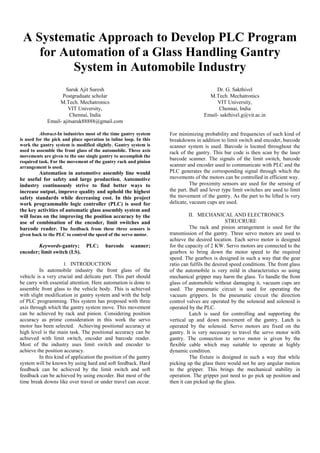
Barcode reader, encoder and limit switches are
used to get better position accuracy. Fig. (c) shows the
integration of these three sensors with PLC module.
The 24V power supply is given to the PLC. When
servo motor starts running then the incremental encoder
counts the number of pulses. These numbers of pulses are
then count in counter block of PLC. At the same time when
gantry hit the limit switch, the limit switch will generate a
signal and at the same time the barcode reader read the
barcode and gives the exact position value of gantry.
PLC logic is developed in such a way that when
these three signals are true only then the next command will
be given to the gantry system. Encoder, limit switch and
barcode reader are connected in series in ladder
programming
Fig. (d) Integration of encoder, limit switch and barcode
reader with PLC
Fig. (e) Timing diagram for glass handling gantry system