Downloaded 792 times
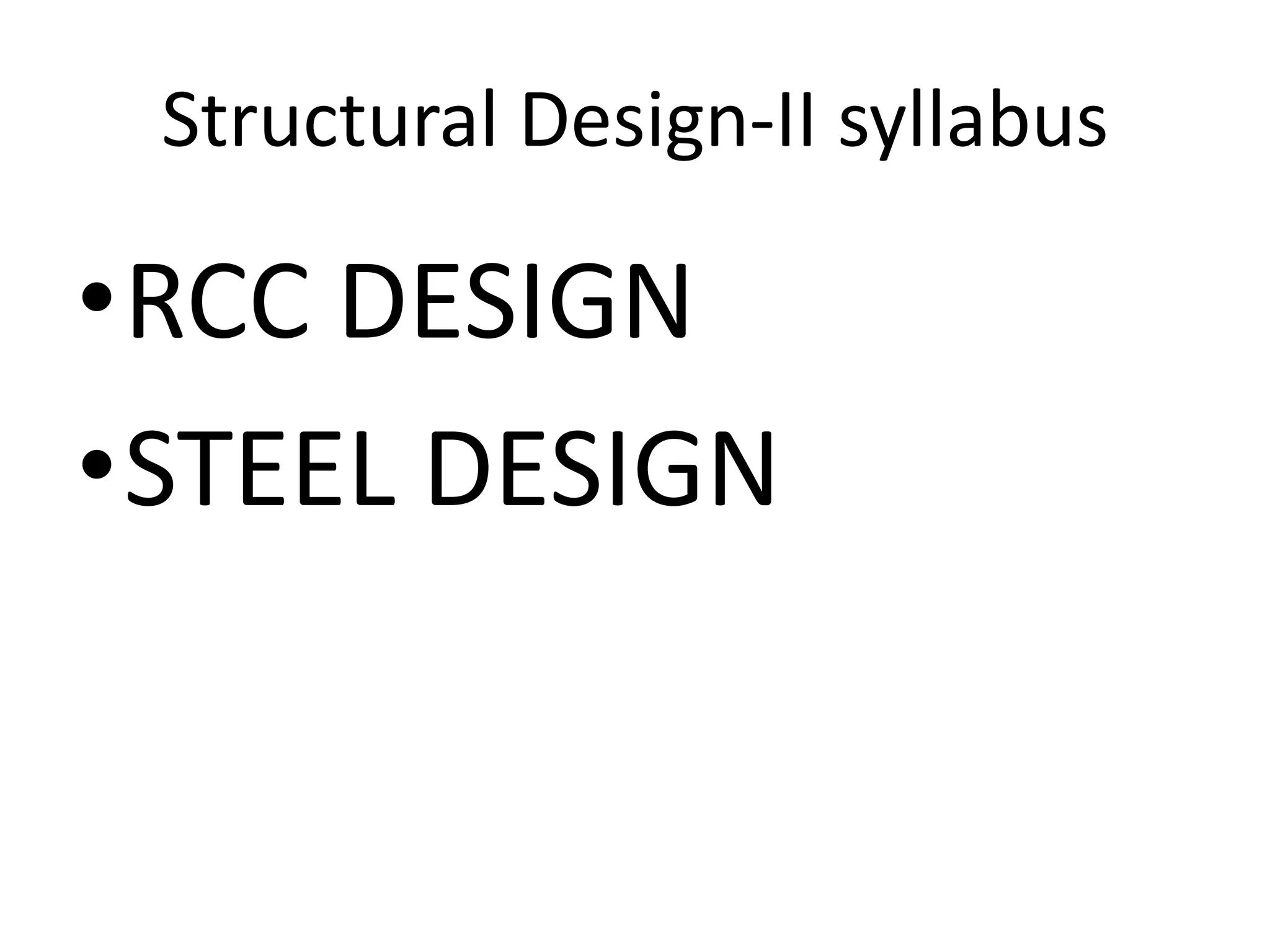
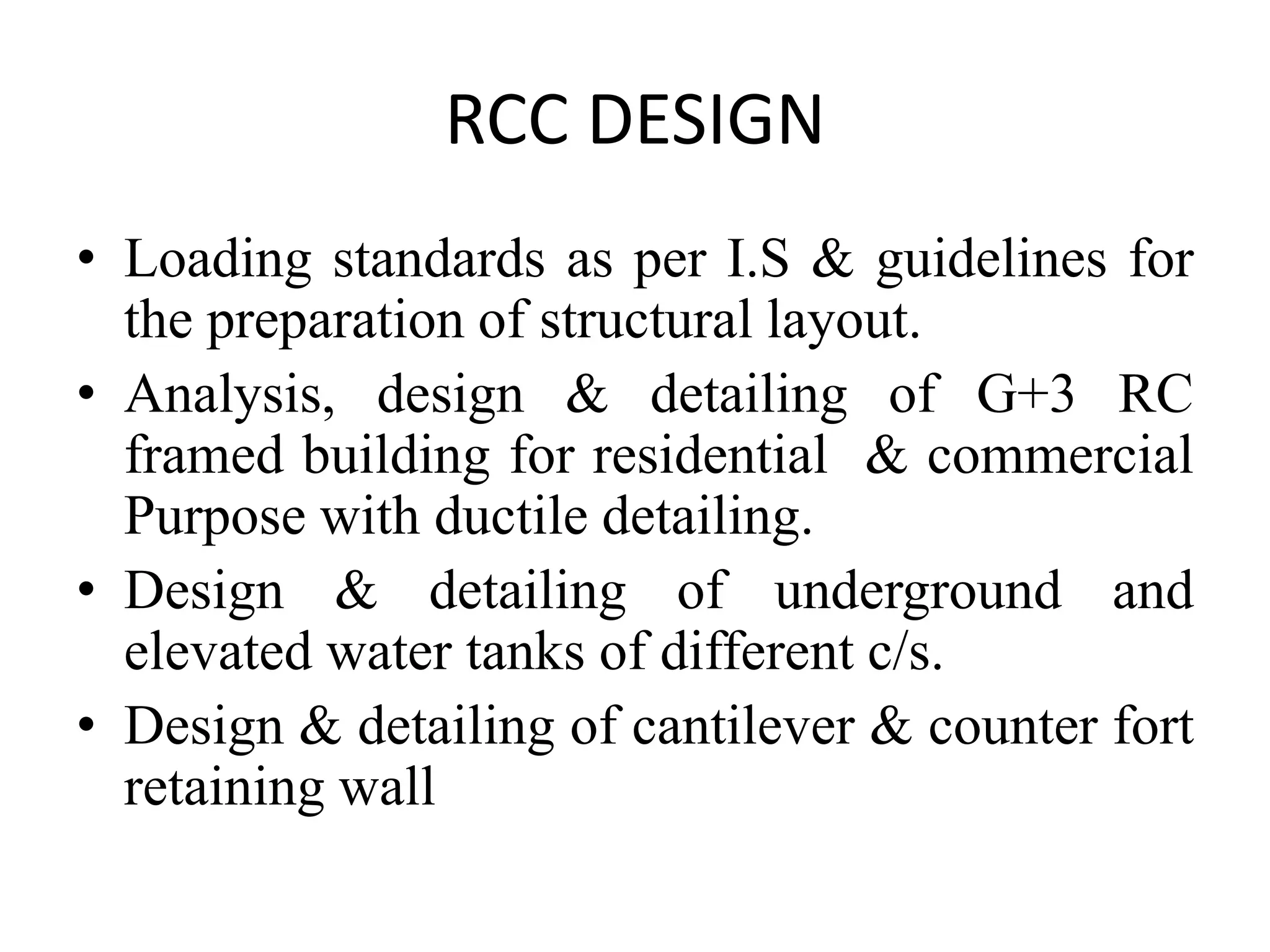
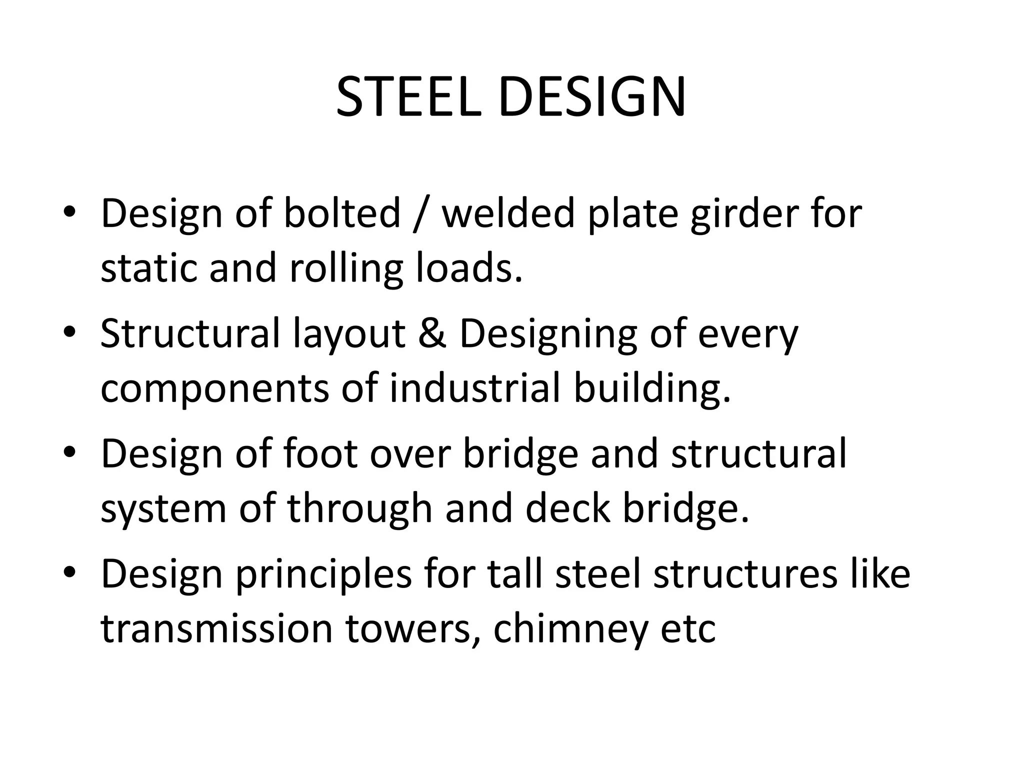
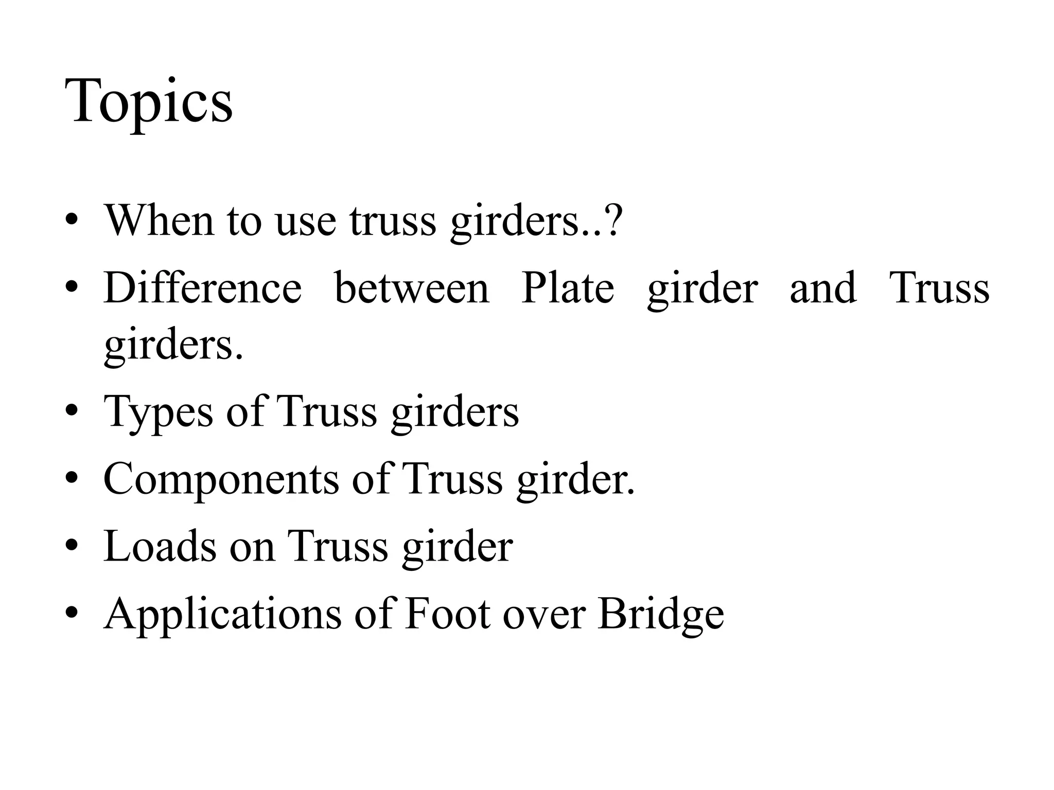
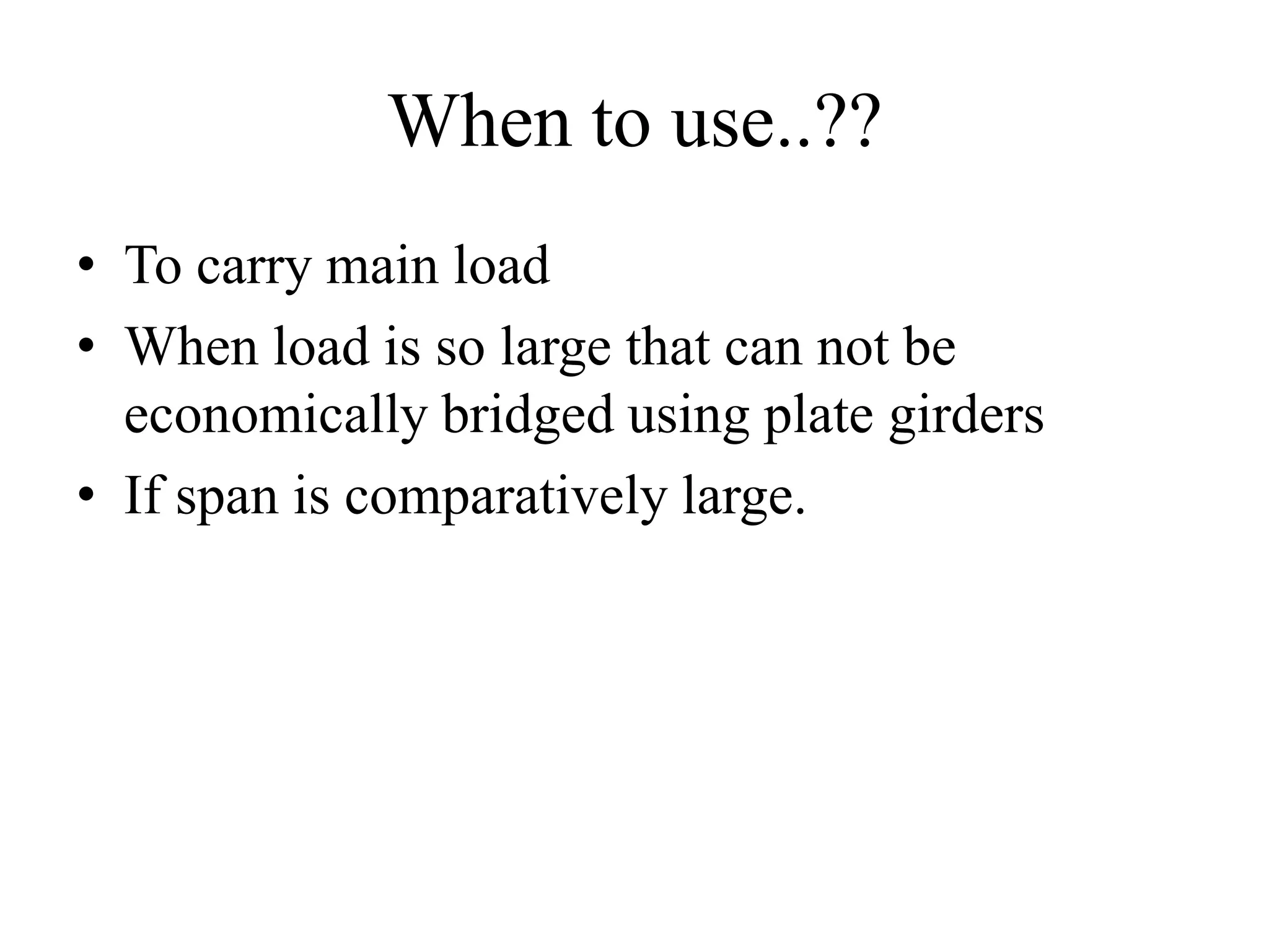
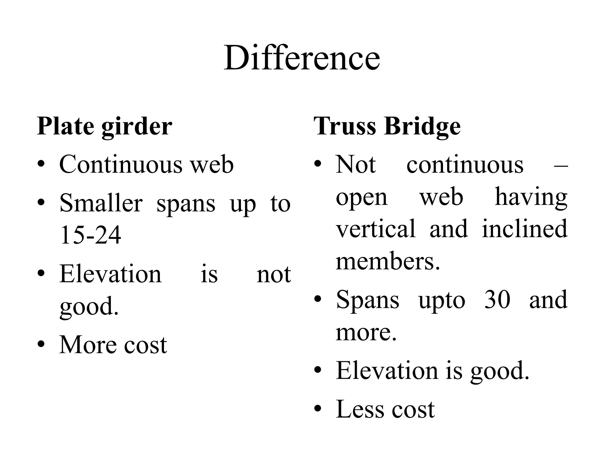
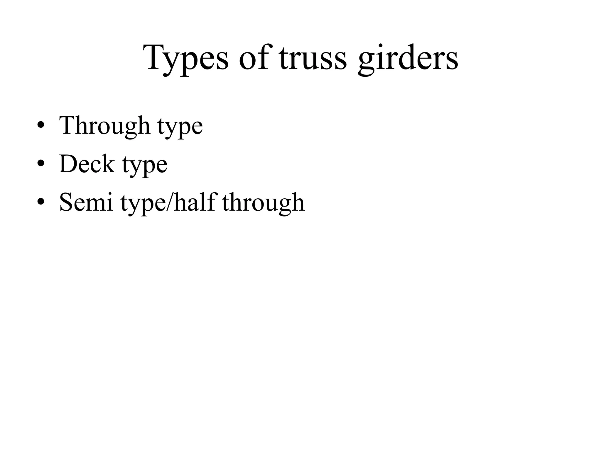
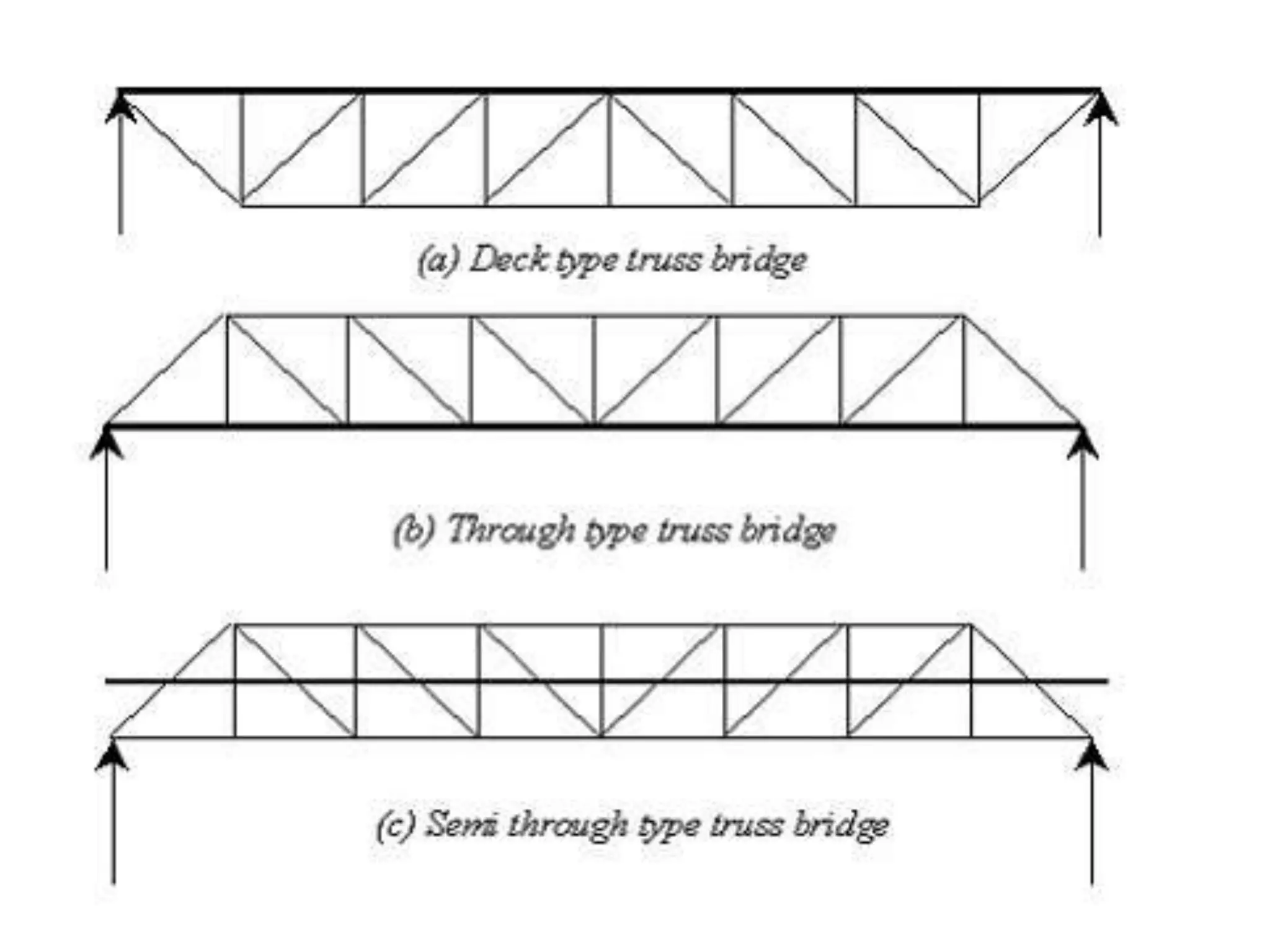
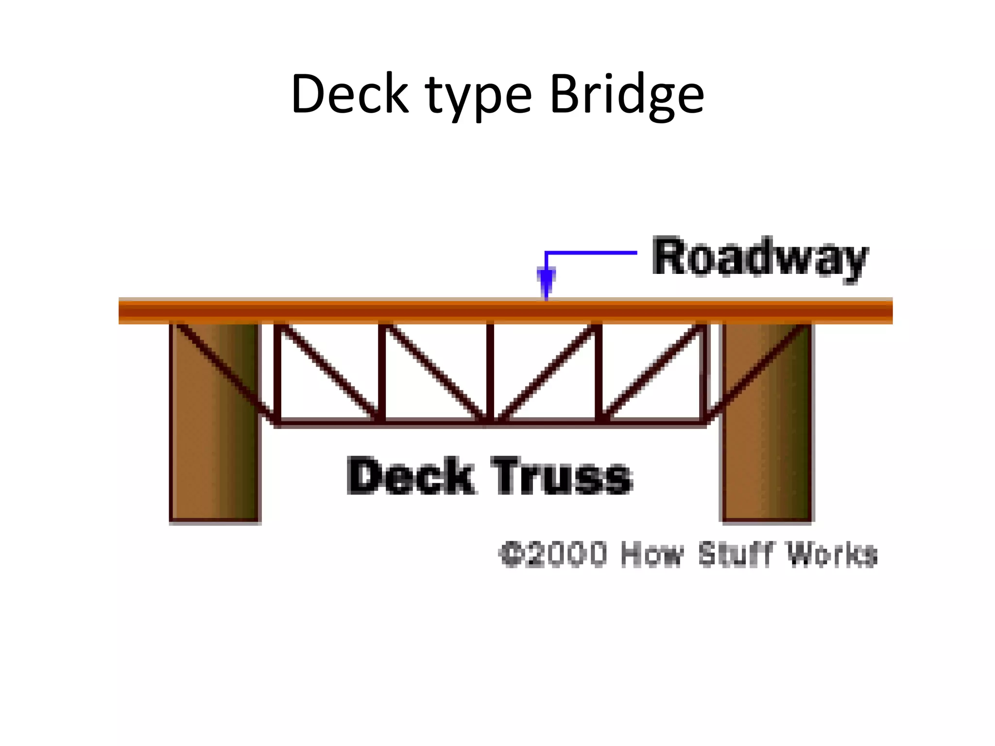
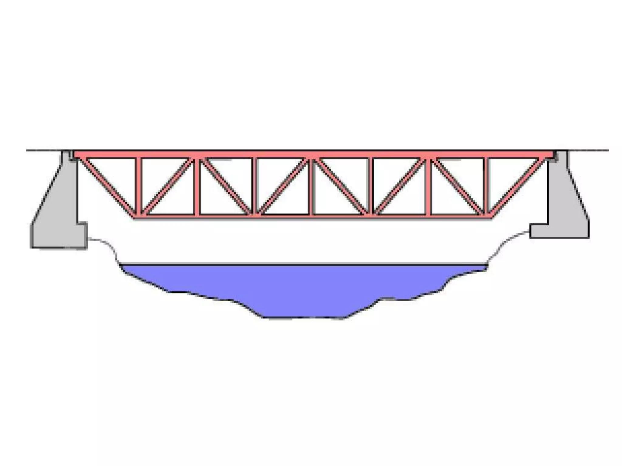
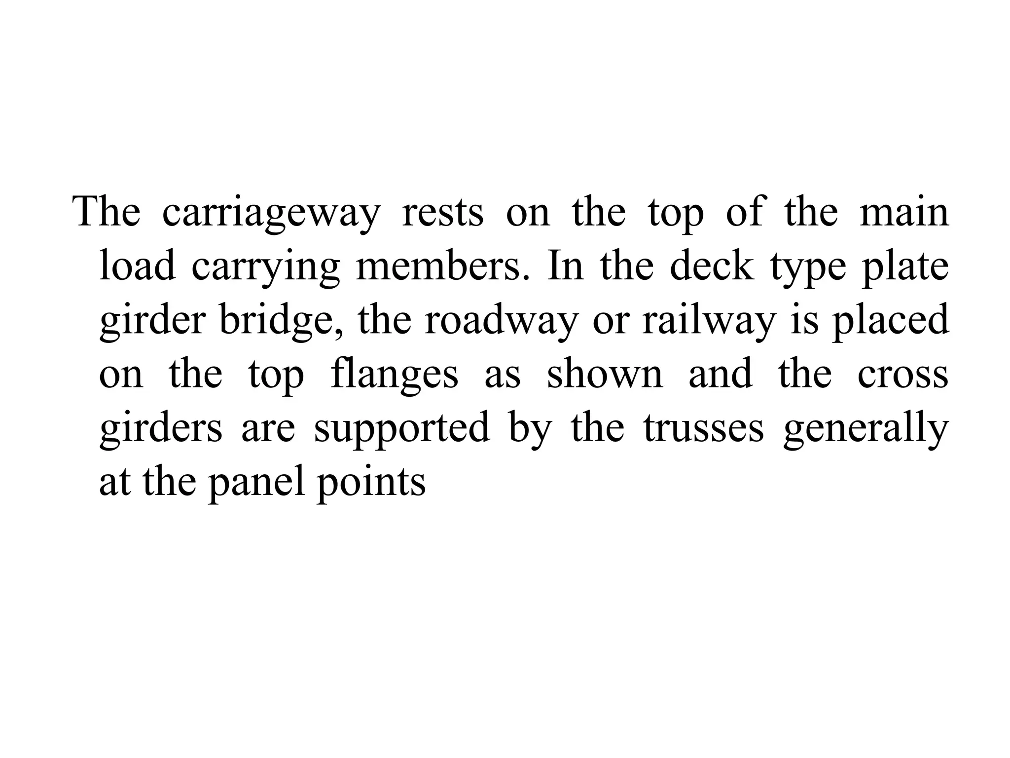
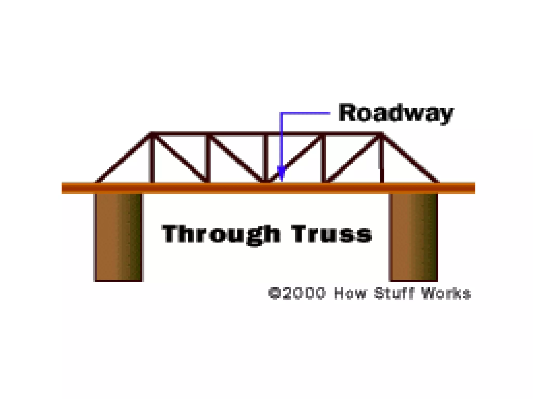
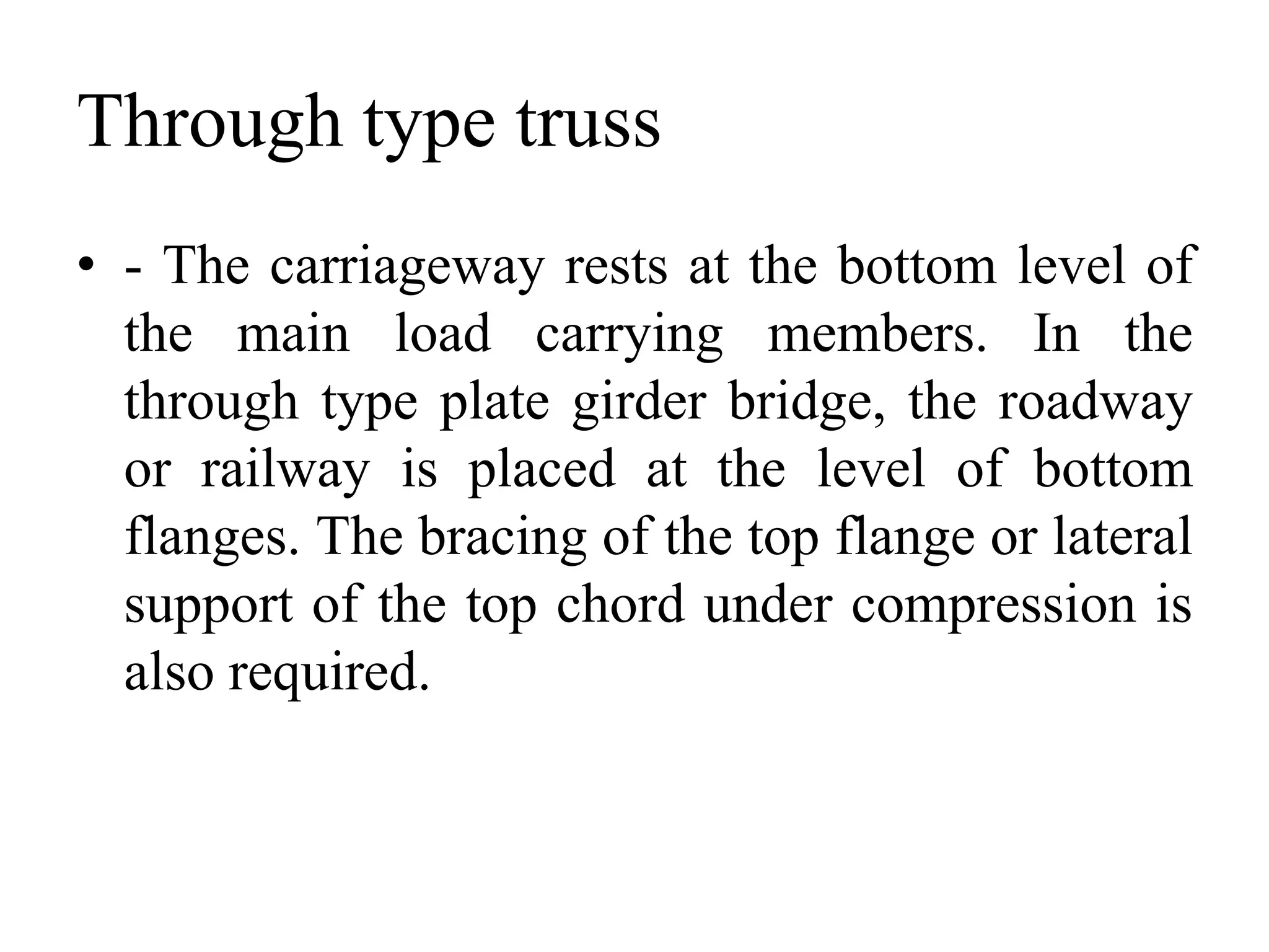
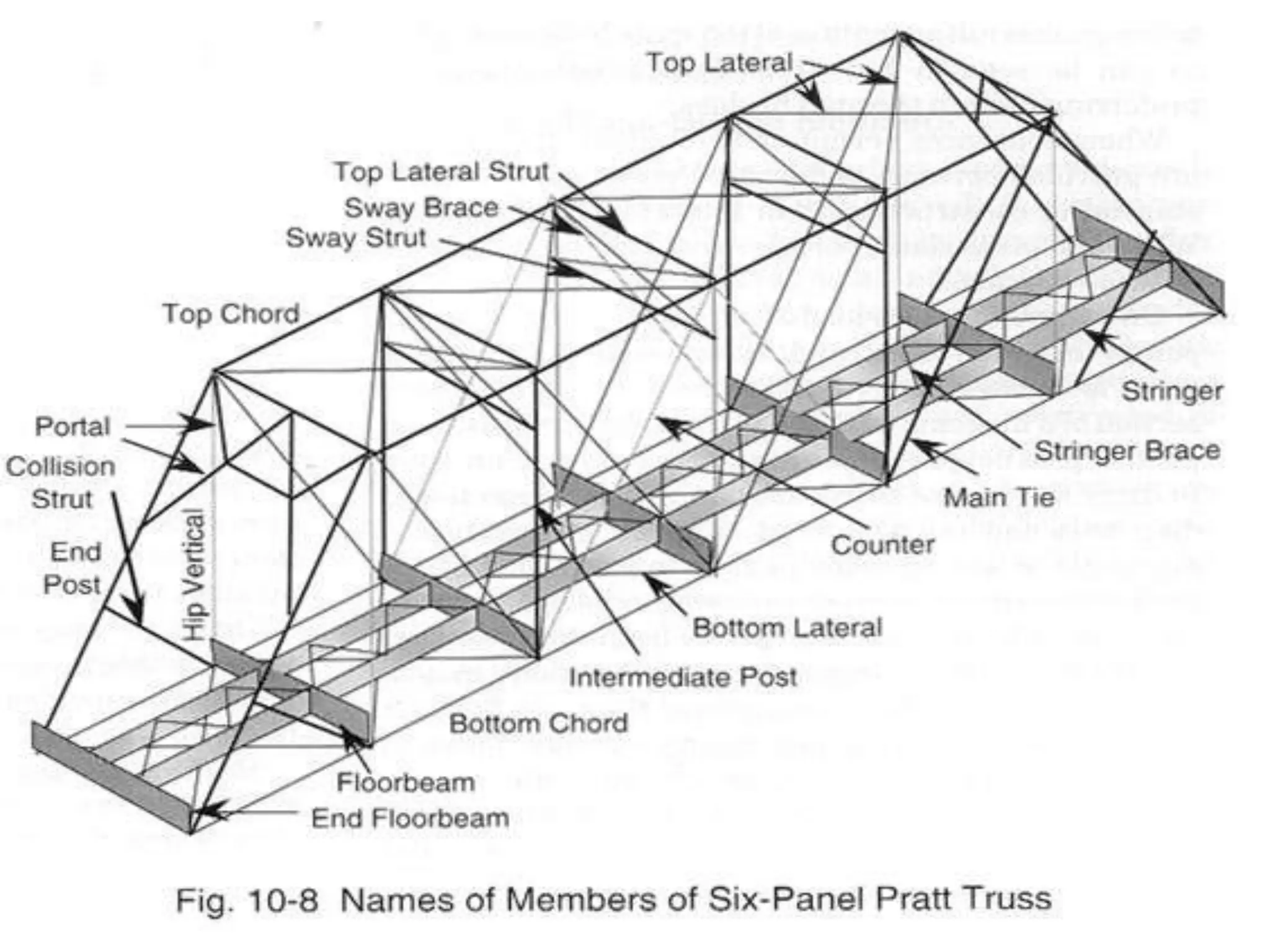
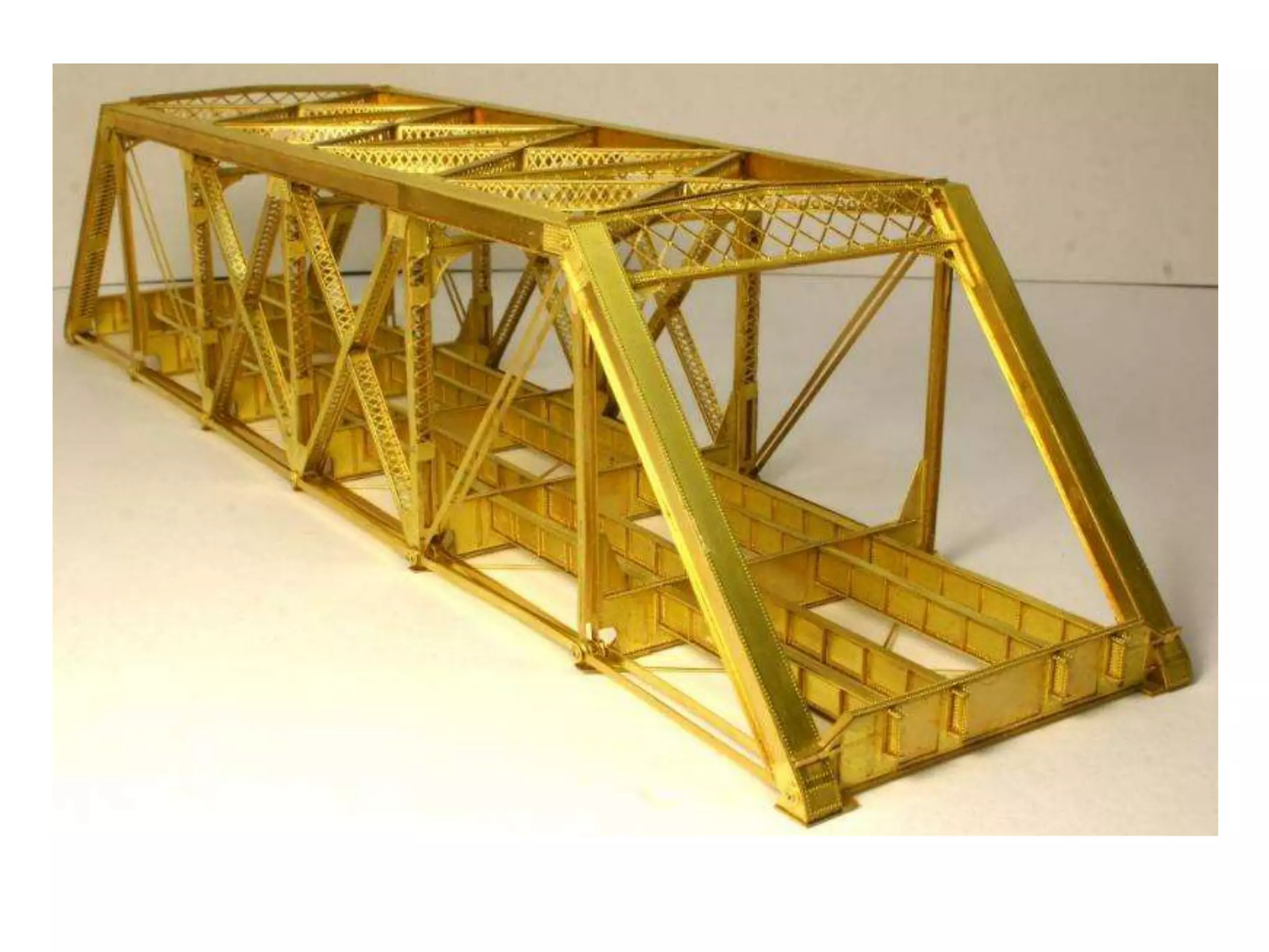
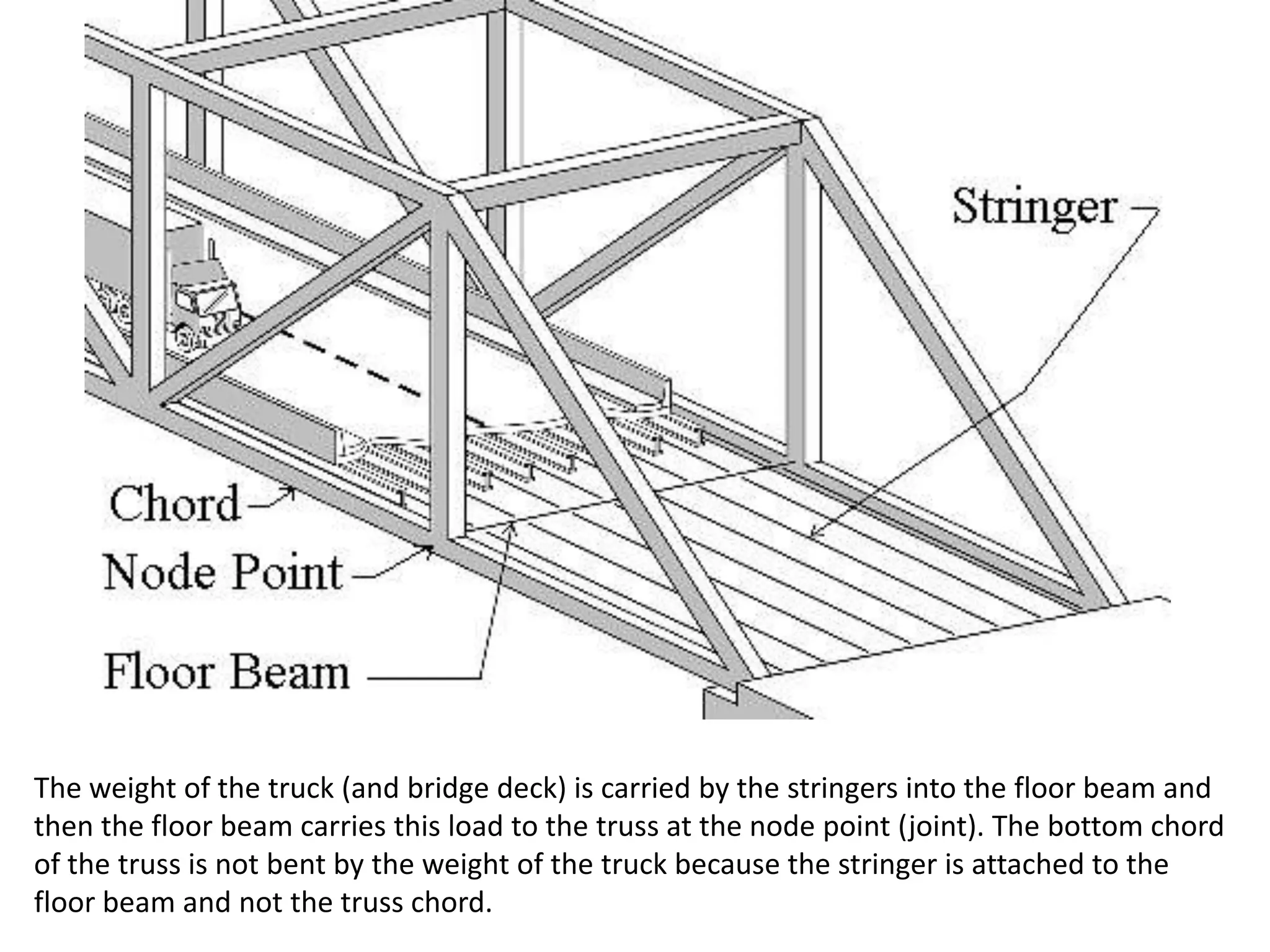
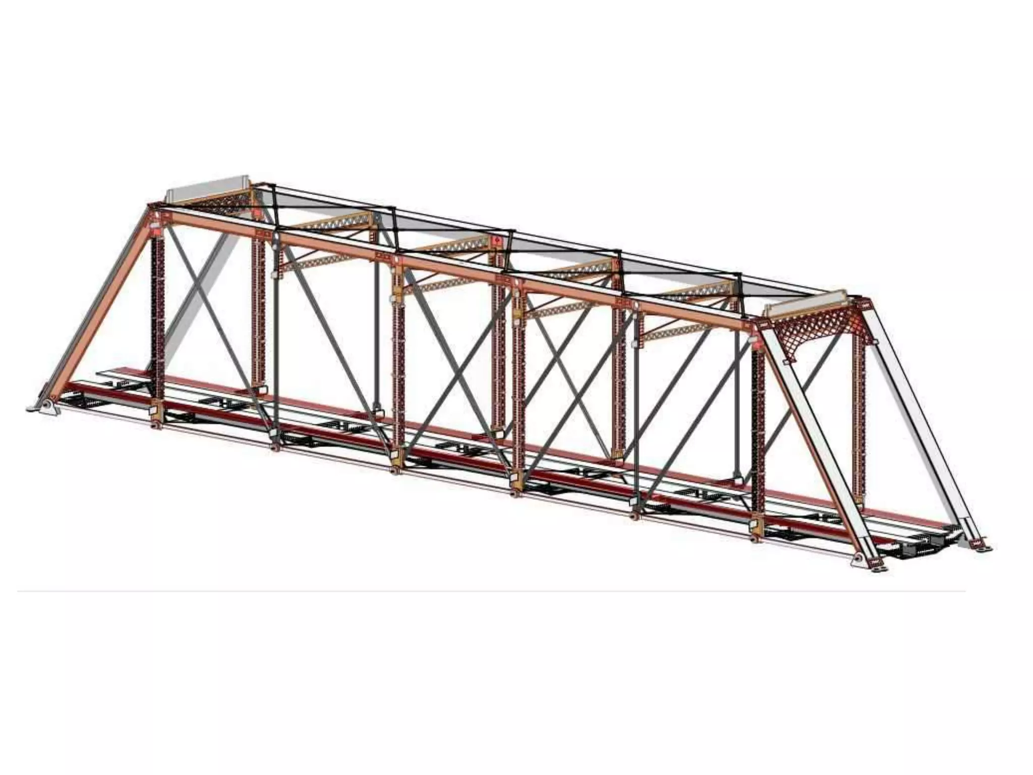
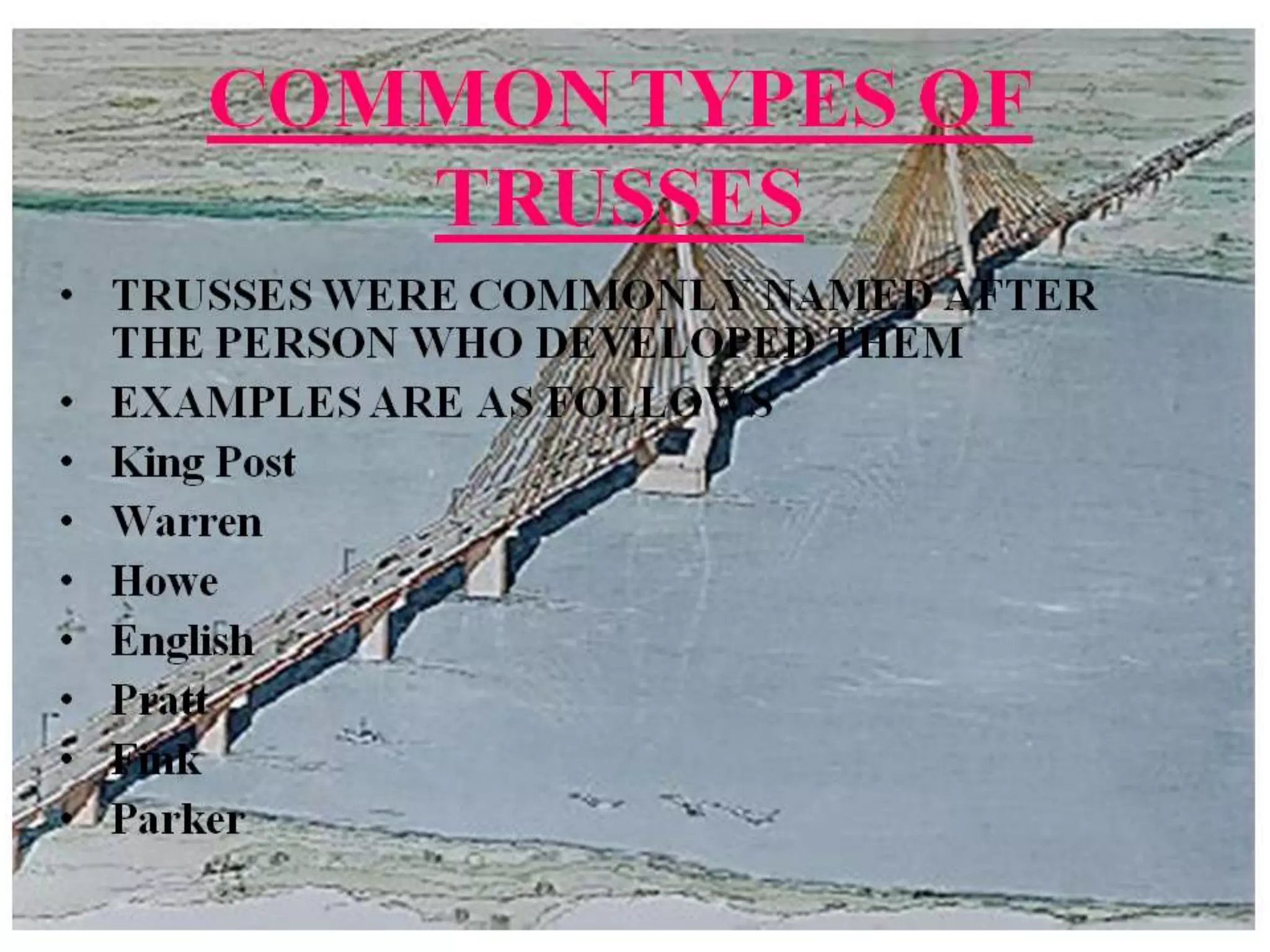
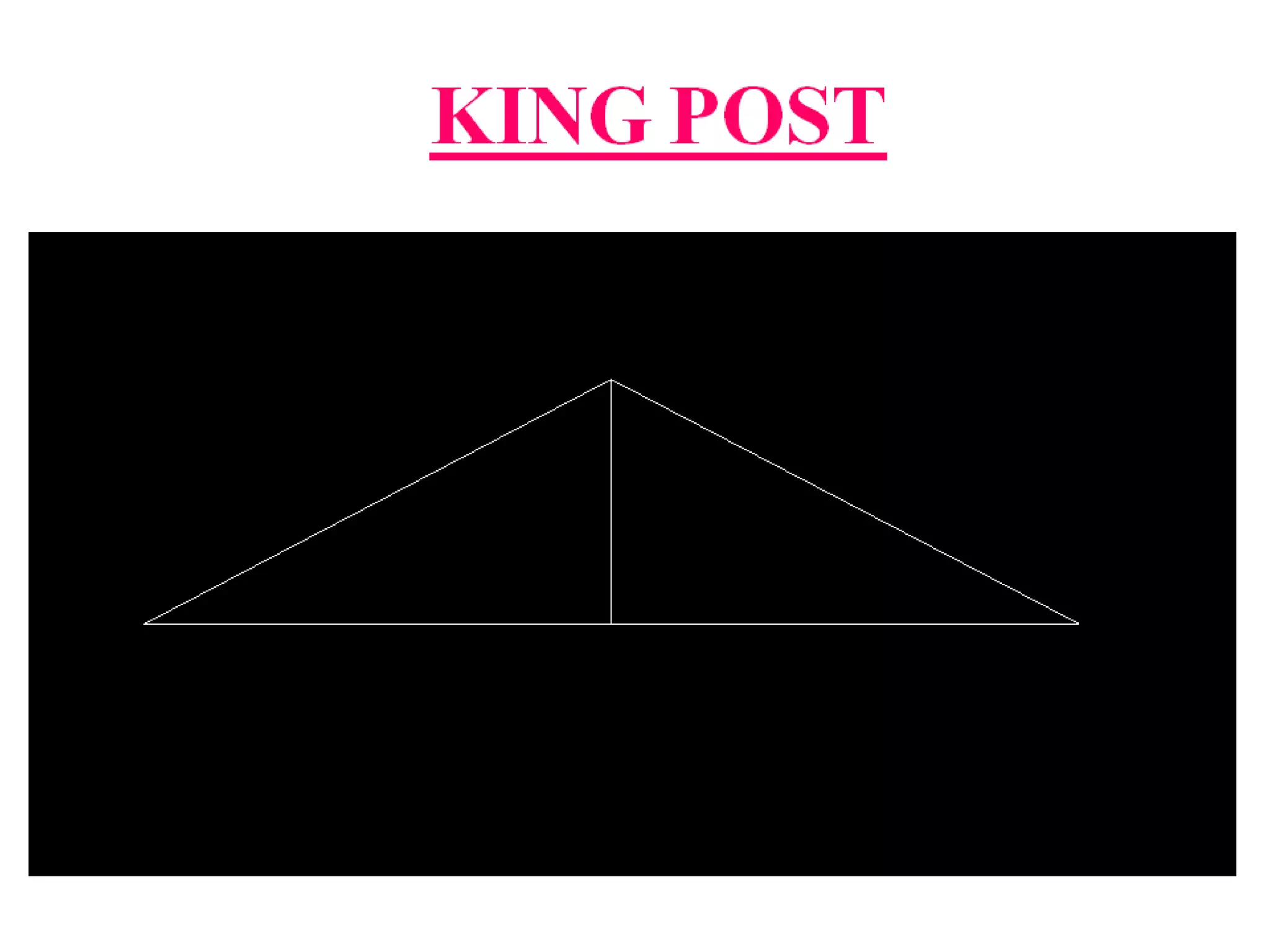
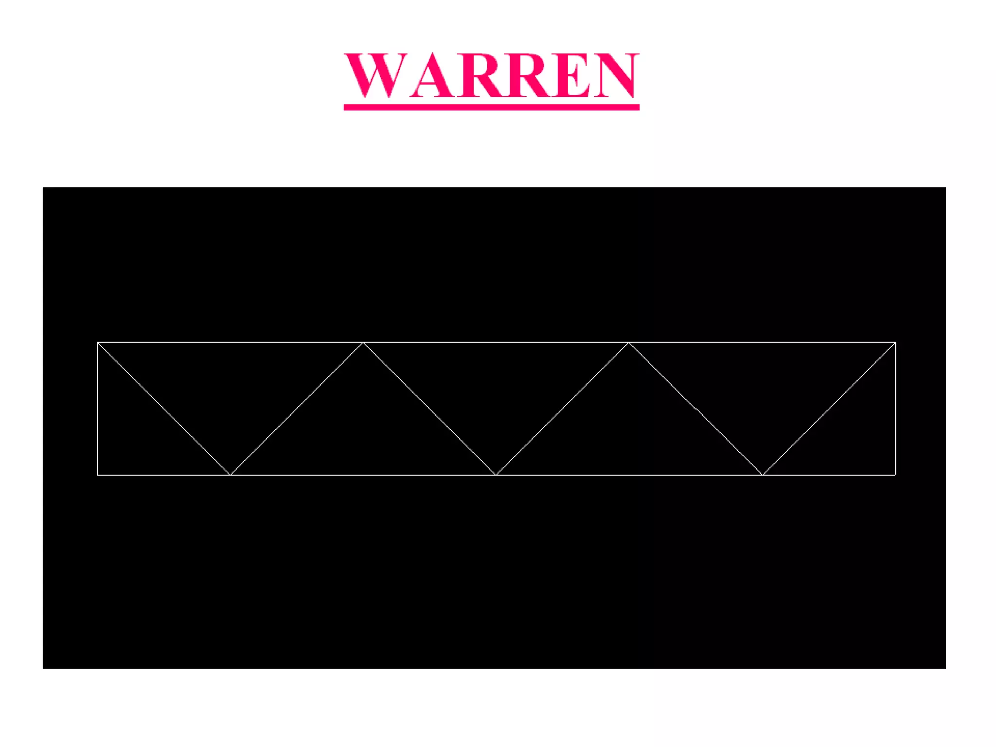
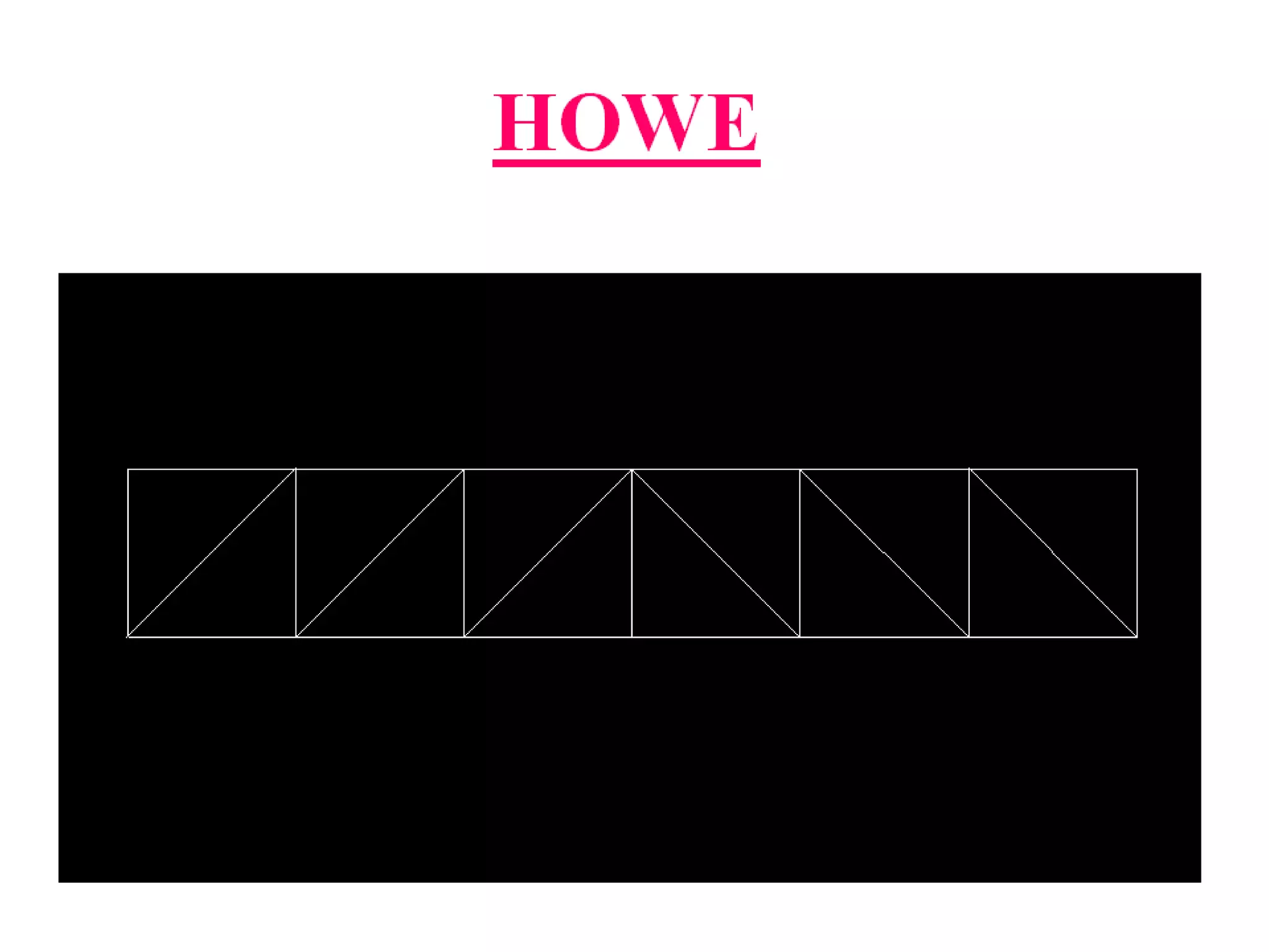
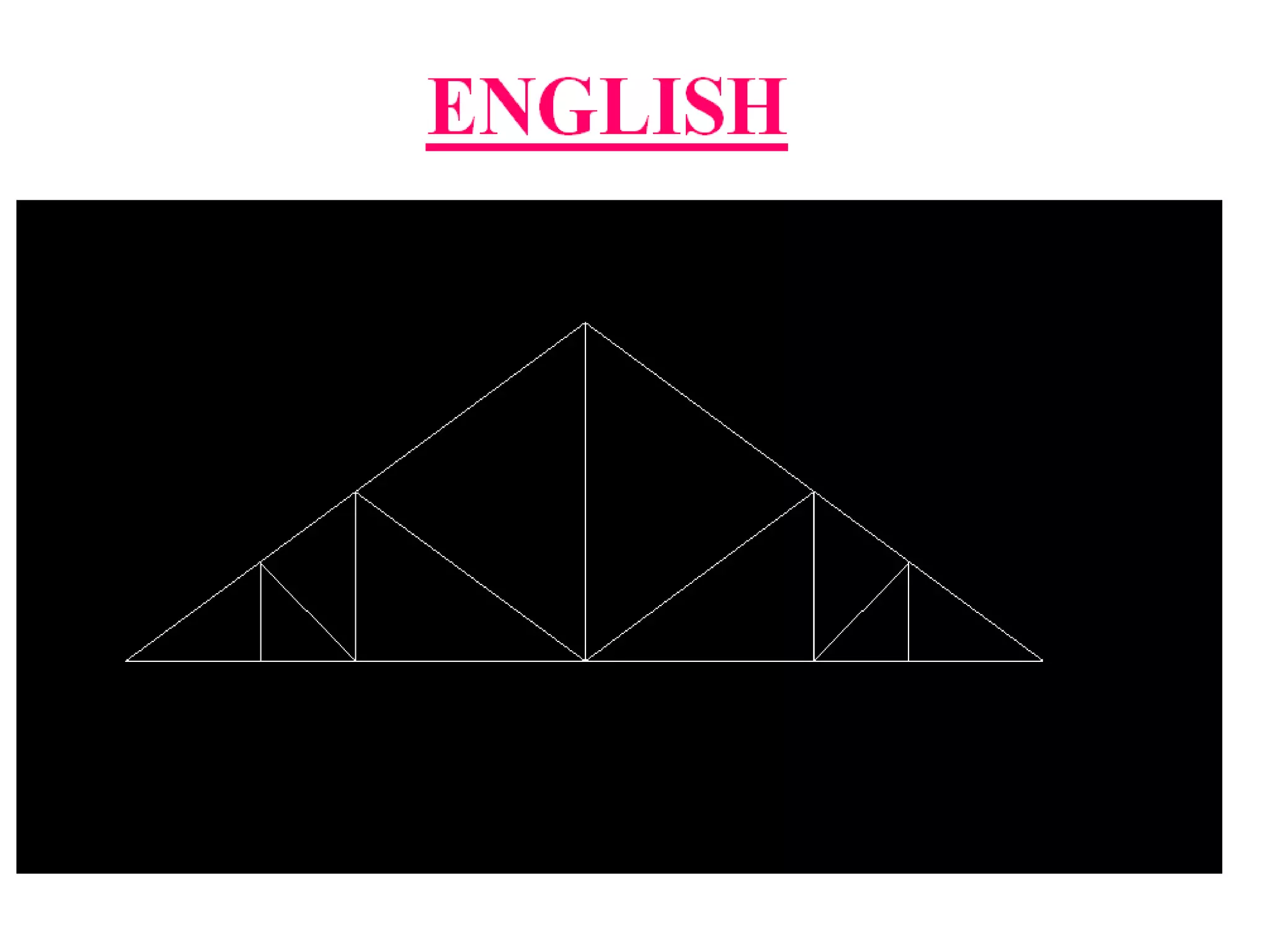
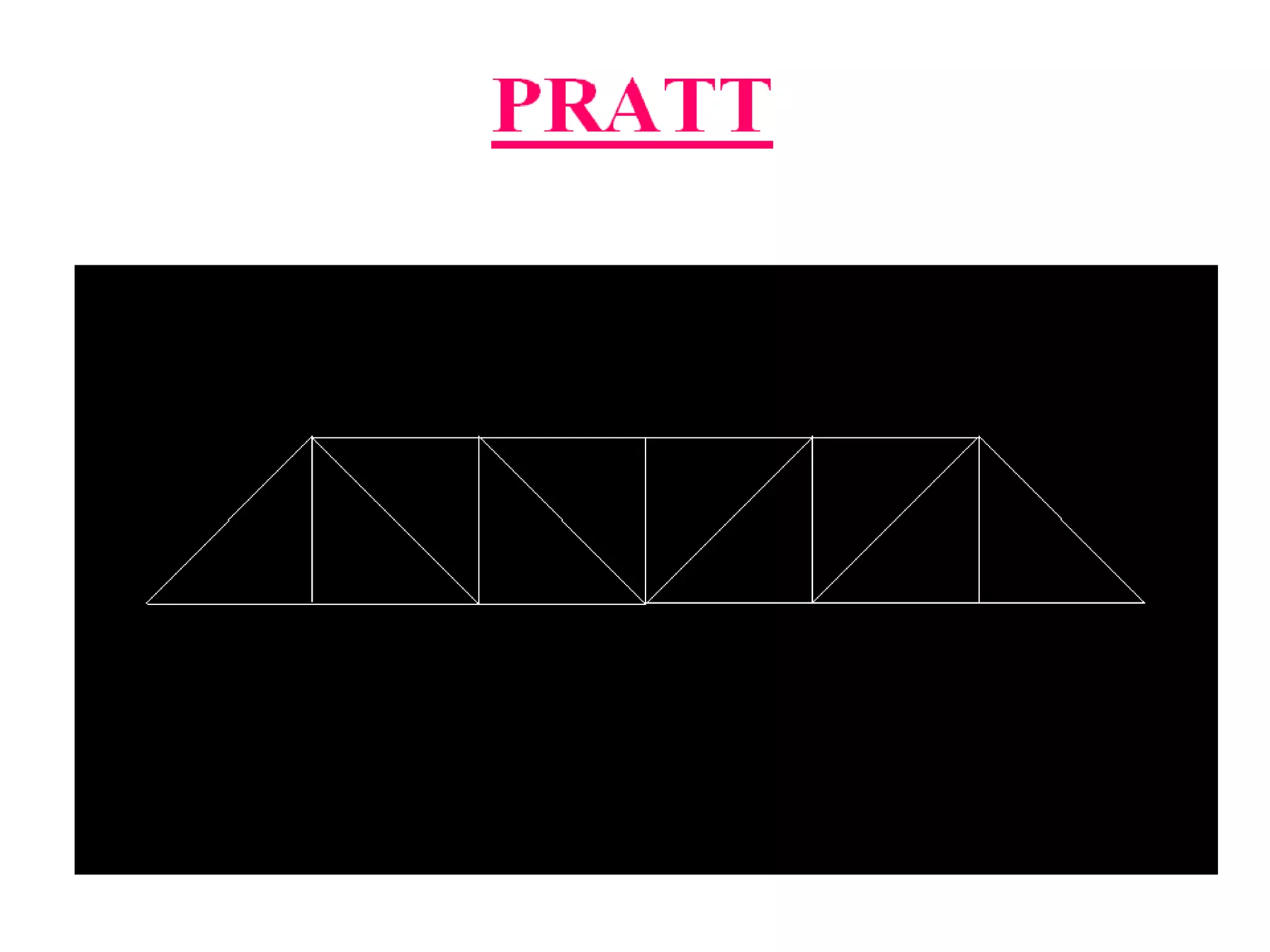
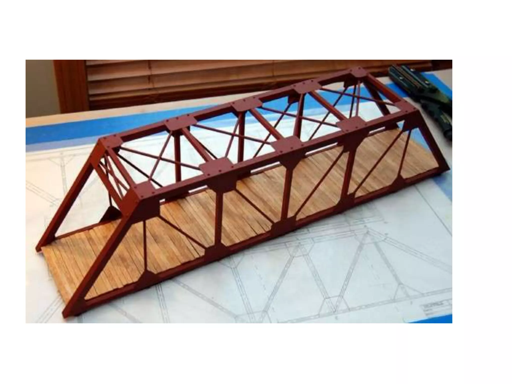
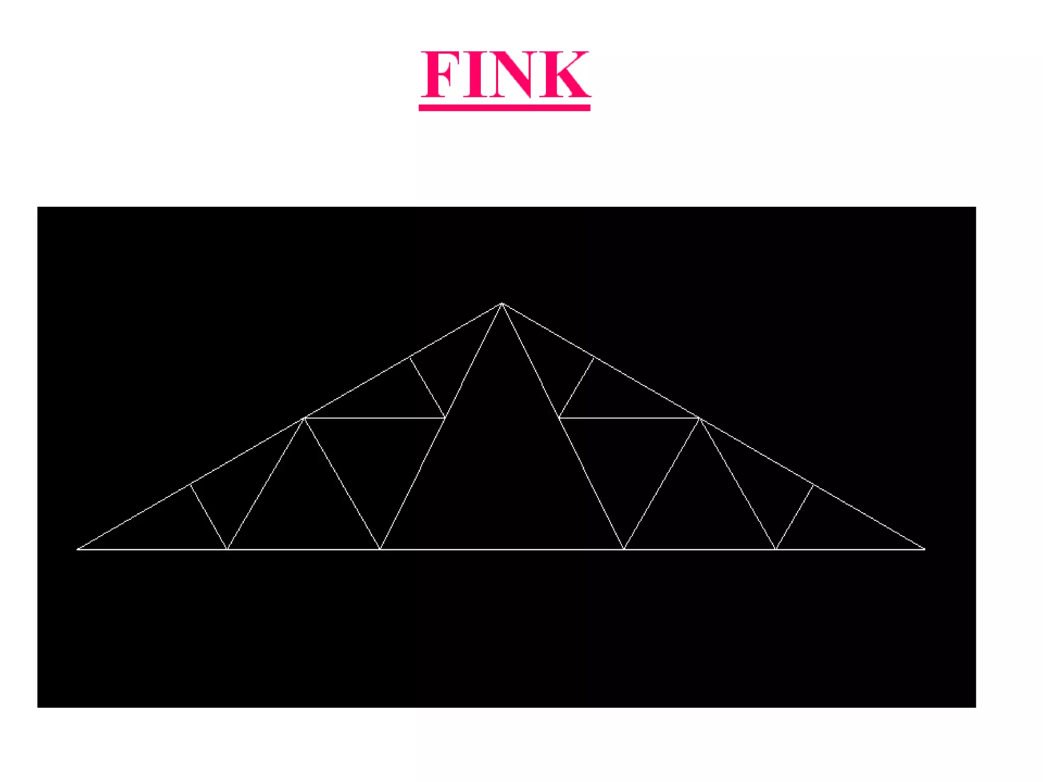
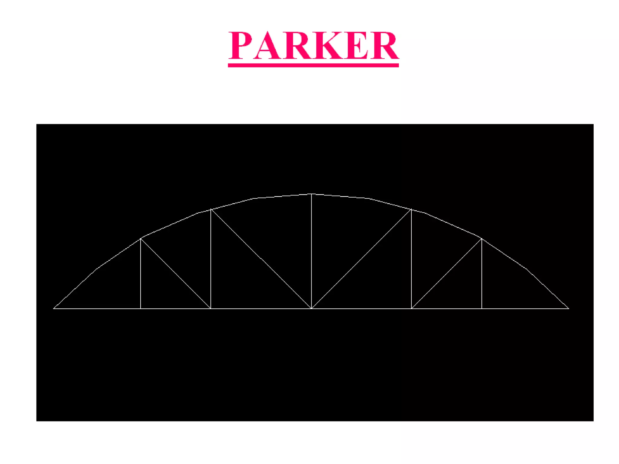

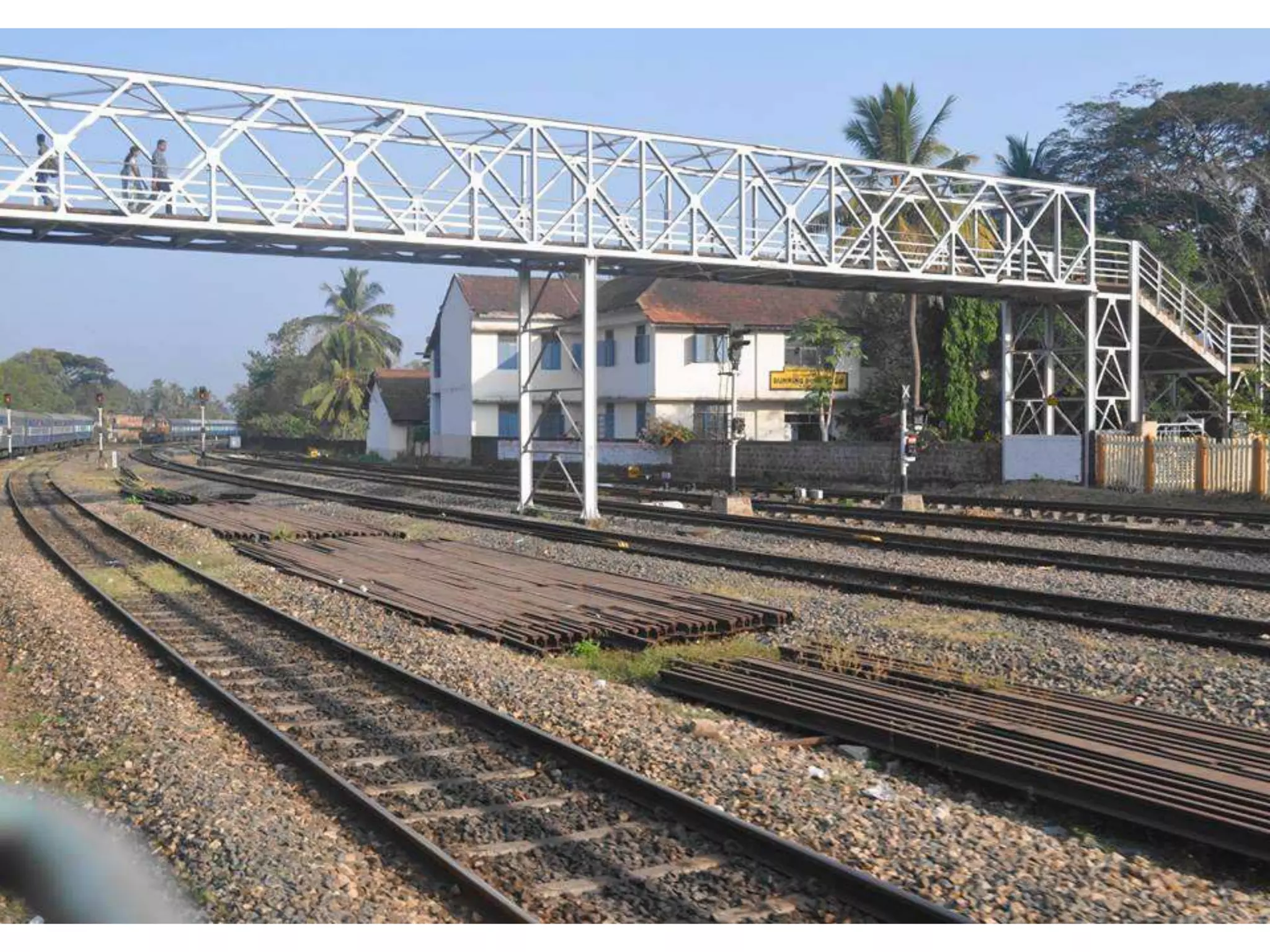

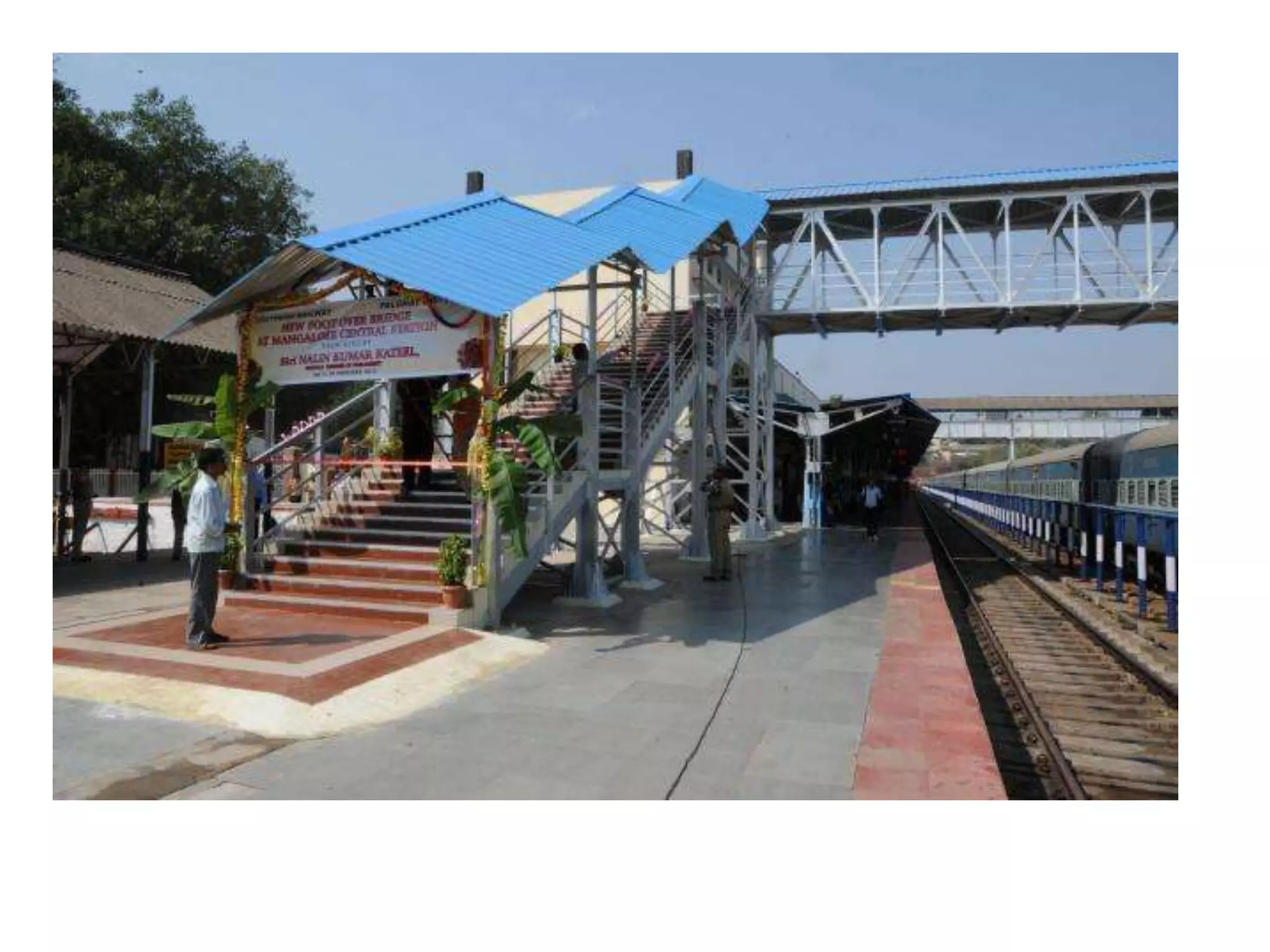
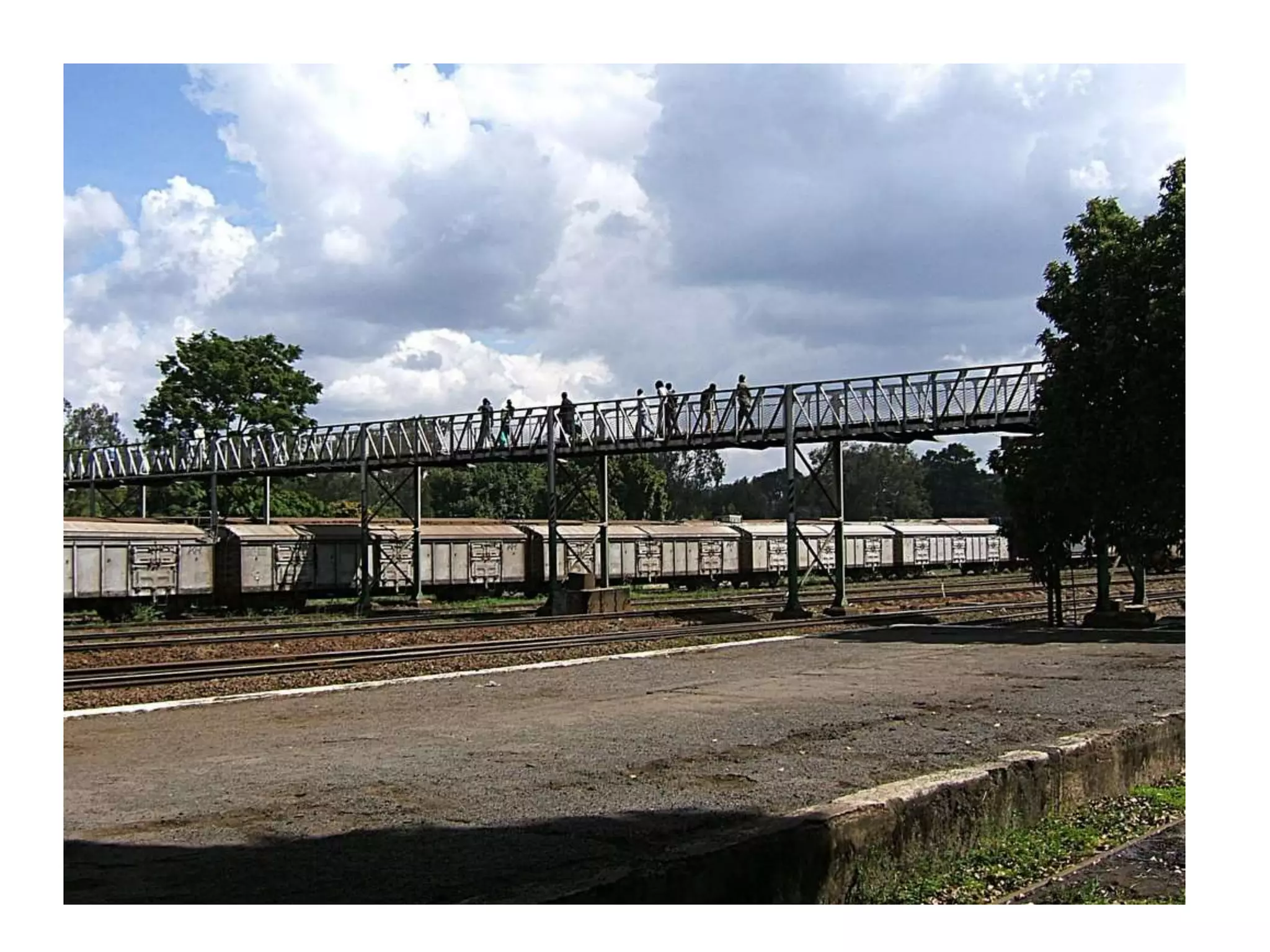

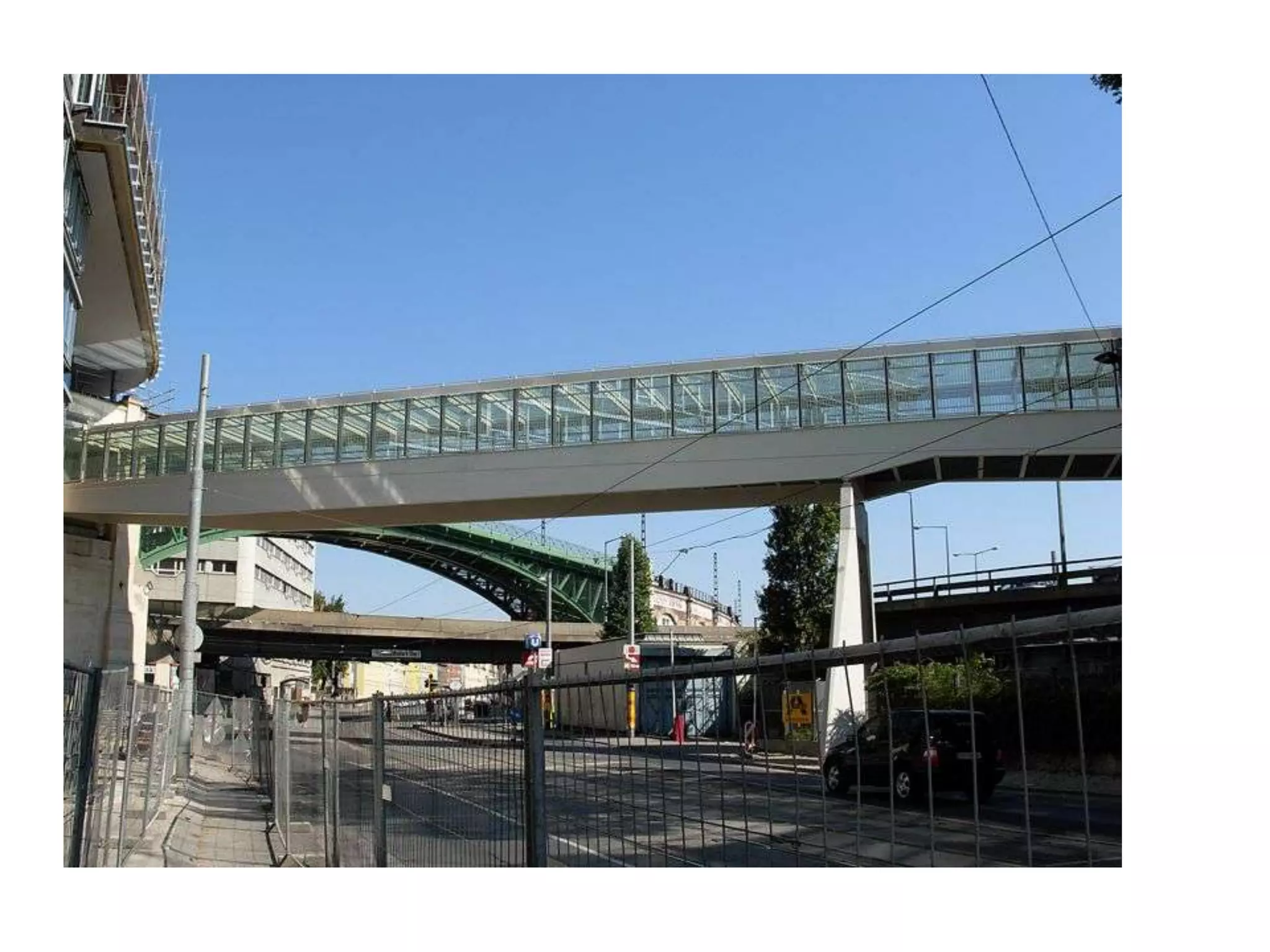
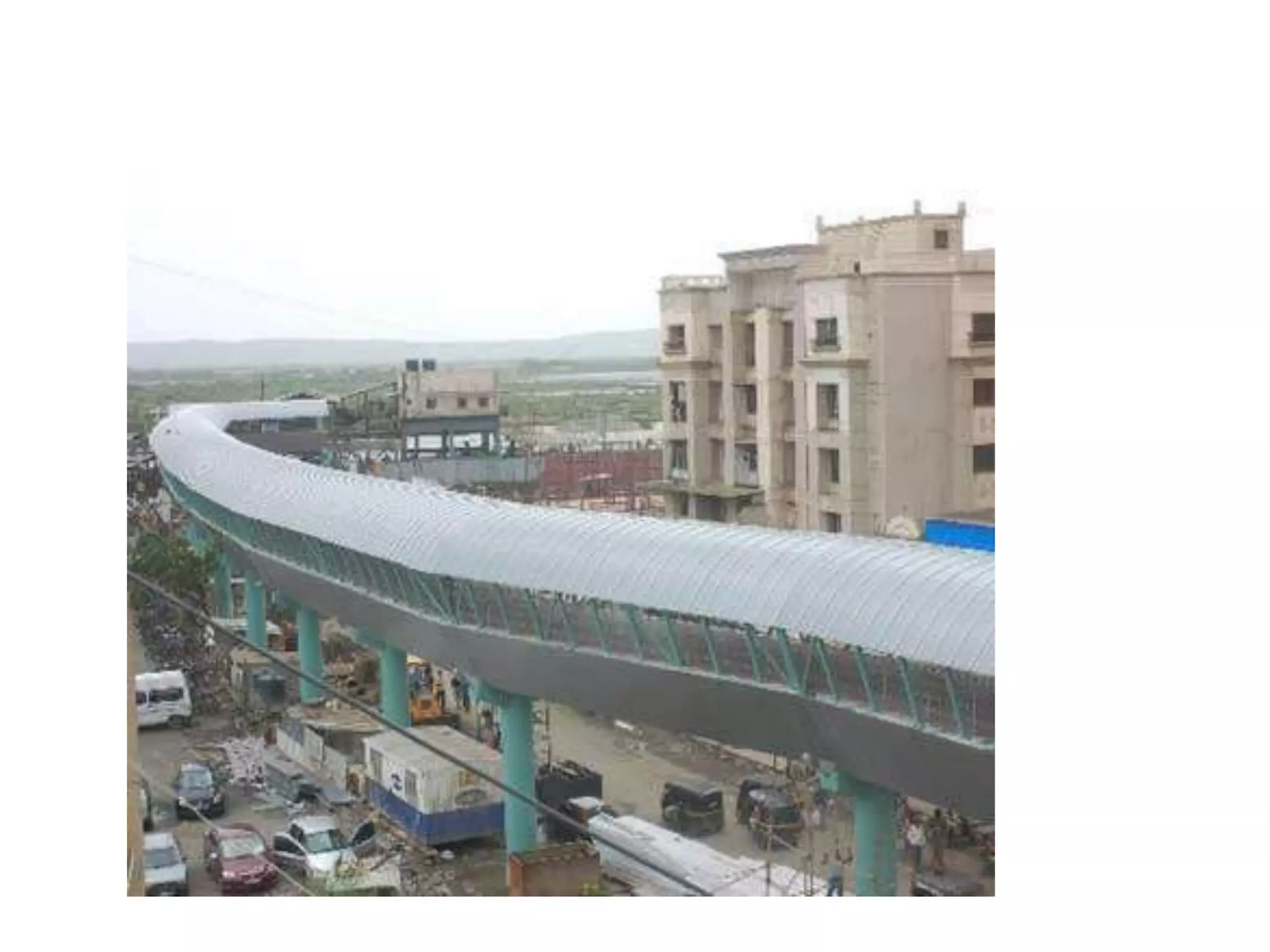
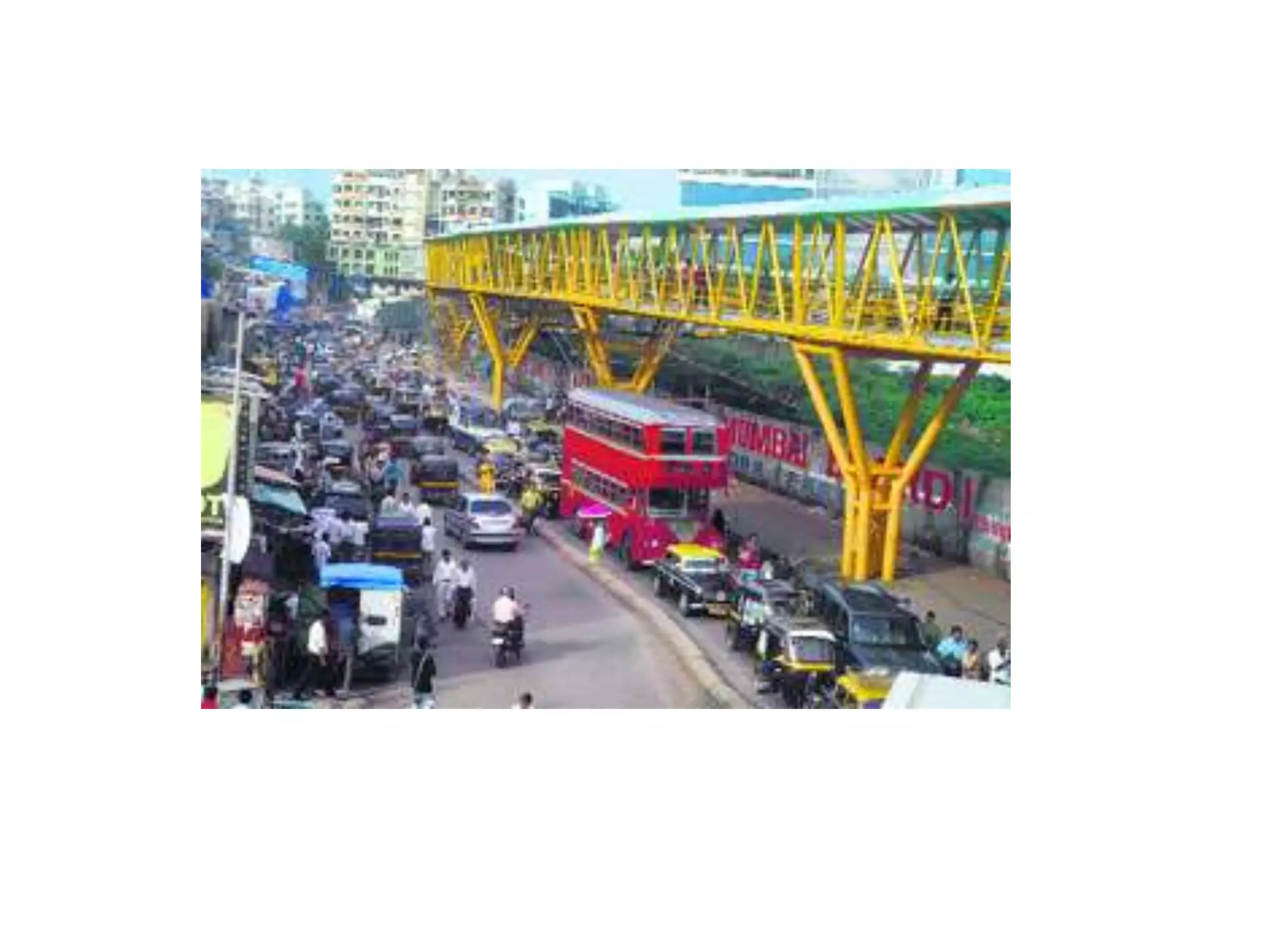
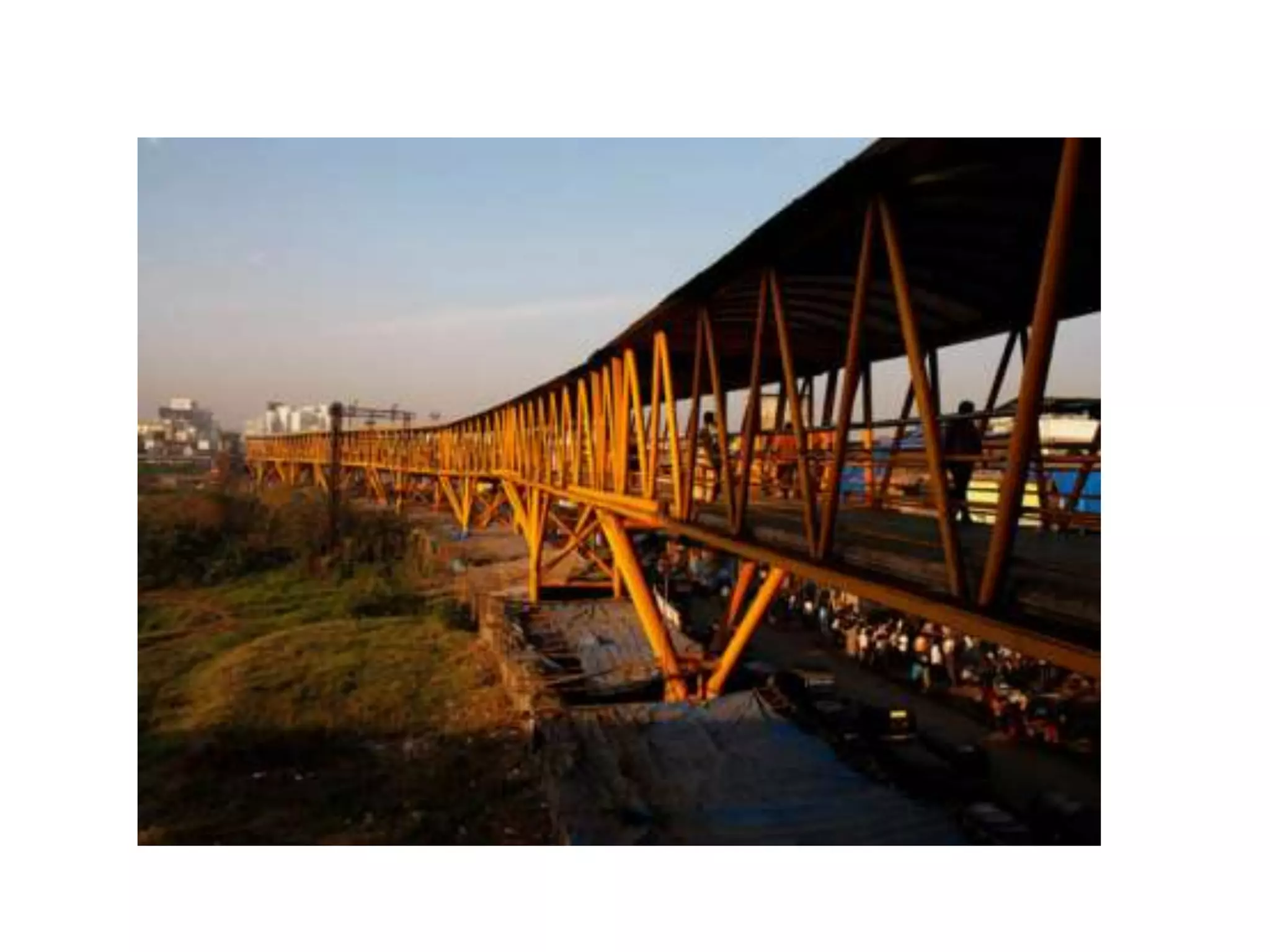
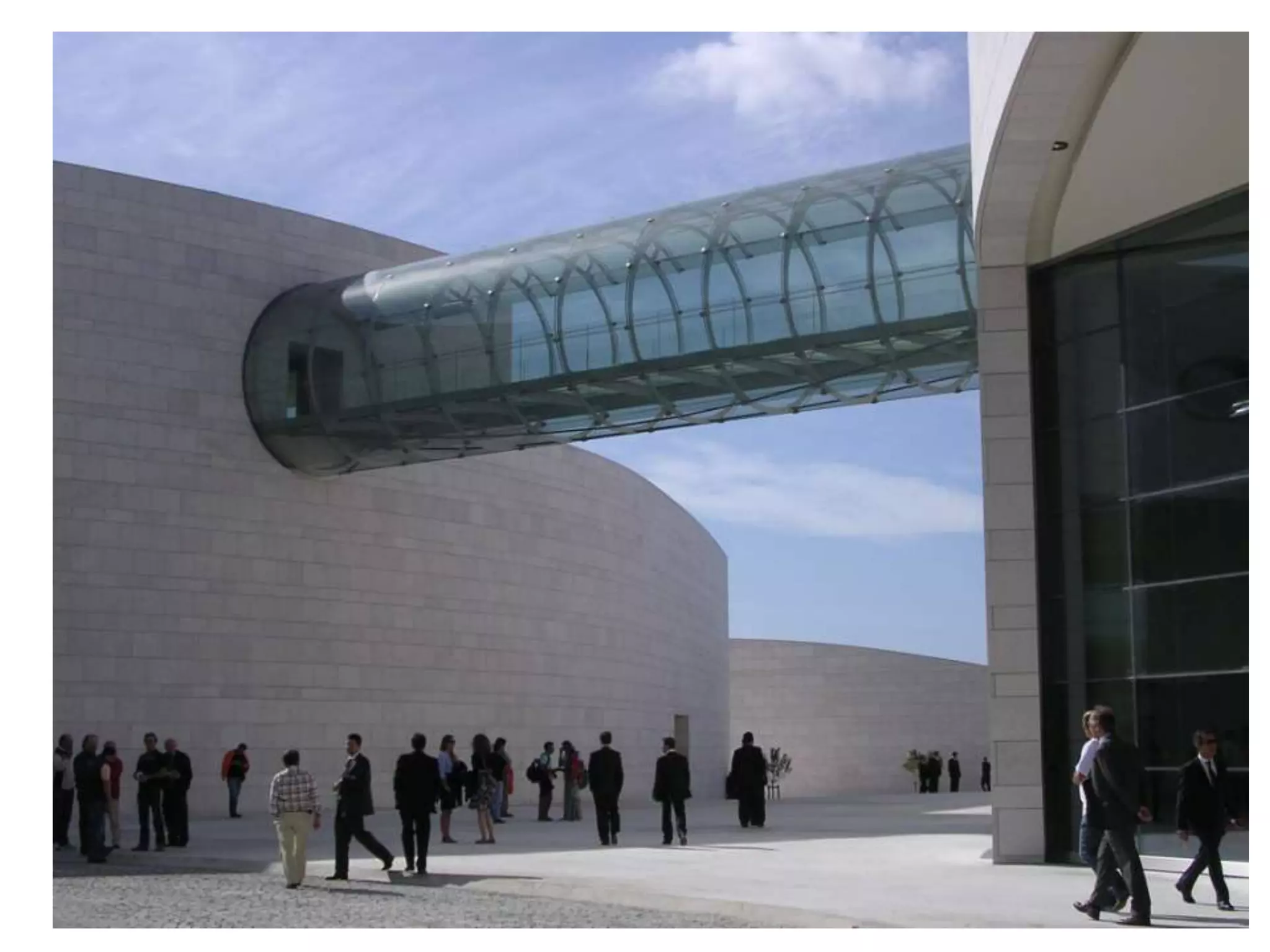
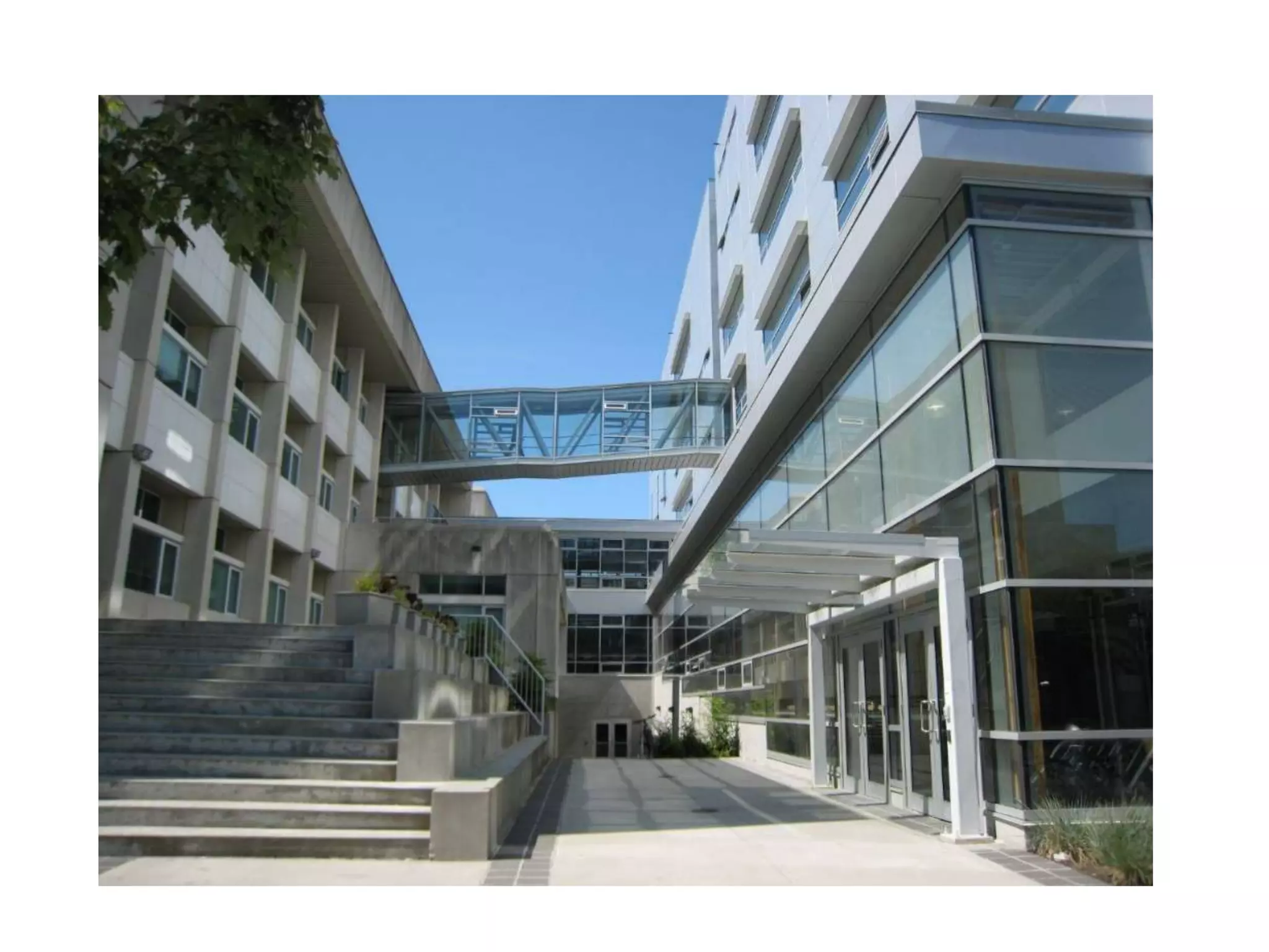


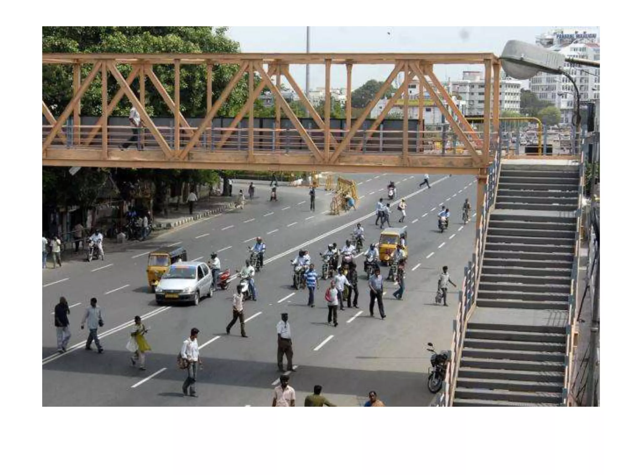
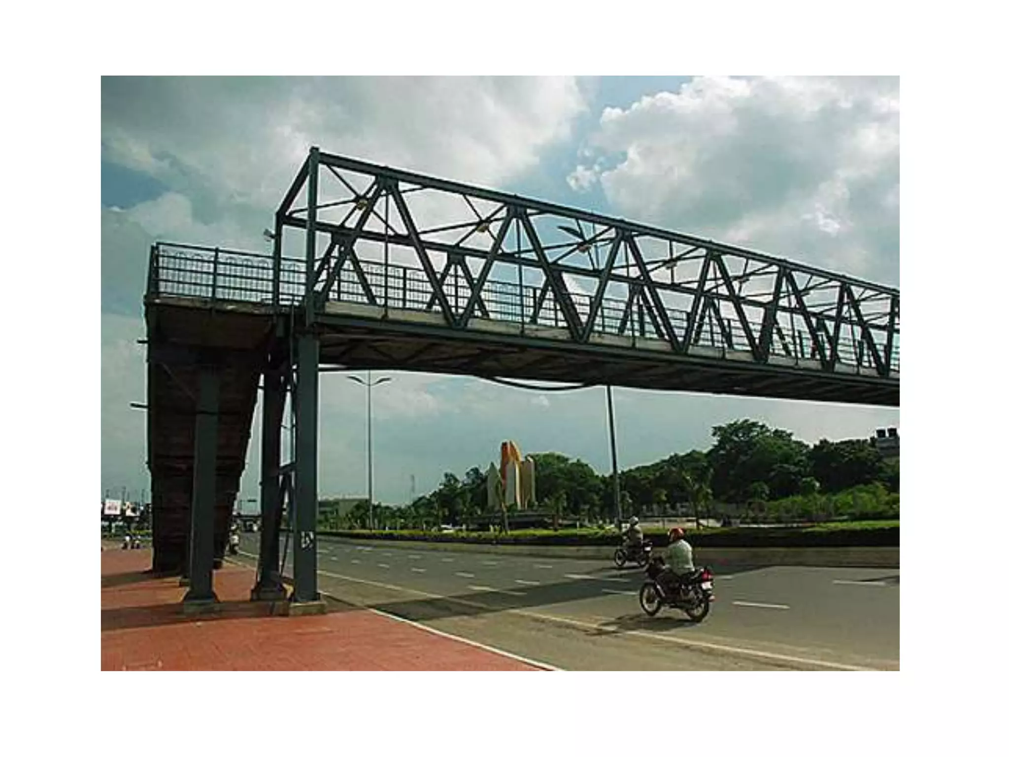


The document outlines the syllabus for a Structural Design-II course, covering Reinforced Concrete Design (RCC) and Steel Design topics. For RCC Design, it includes loading standards, analysis and design of a G+3 residential/commercial building, and design of water tanks and retaining walls. Steel Design topics are plate girder design, industrial building design, and design of foot over bridges, transmission towers and bridges. The document also discusses specific topics related to foot over bridge design, including when to use truss girders, types of truss girders, their components, applicable loads, and applications of foot bridges.


