Pipeline design
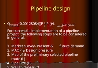
Qmmscfd=0.00128084((P2-P 2)/L
mmscfd 1 2 miles)0.51D2.53
For successful implementation of a pipeline
project, the following steps are to be considered
in general:
1. Market survey- Present & future demand
2. MAOP & Design pressure
3. Map of the preliminary selected pipeline
route (L)
4. Pipe Size (D)
3.
Pipeline design (contd.)
6. Pipe specification / grade
7. Bill of materials
8. Total cost estimate
9. Selection of ROW
10.Detailed survey and Preparation of
alignment drawings
4.
Pipeline design
( contd.)
Loadconsideration:
In earlier days , pipeline design was done
considering the present load and 15 to
30% increment of load.
Now-a days, the use of natural gas increased
tremendously. As a result the concept of
pipeline design has also changed.
Presently pipeline design is being done
considering the present load as well as the
assumed gas load of the that particular area for
the next 20 years ( effective life of the pipeline)
5.
Pipeline design (Contd.)
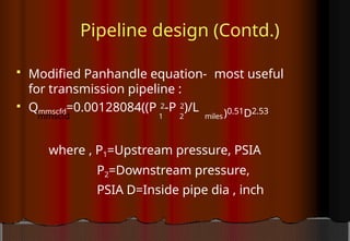
Modified Panhandle equation- most useful
for transmission pipeline :
Qmmscfd=0.00128084((P 2-P 2)/L
mmscfd 1 2 miles)0.51D2.53
where , P1=Upstream pressure, PSIA
P2=Downstream pressure,
PSIA D=Inside pipe dia , inch
6.
Pipeline design (contd.)
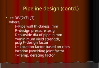
t= DP/(2YFL JT)
where,
t=Pipe wall thickness, mm
P=design pressure ,psig
D=outside dia of pipe in mm
Y=minimum yield strength,
psig F=design factor
L= Location factor based on class
location J=welding joint factor
T=Temp. derating factor
7.
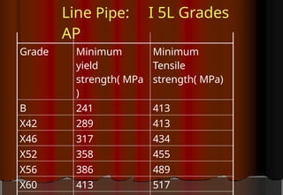
Line Pipe:
AP
I 5LGrades
Grade Minimum
yield
strength( MPa
)
Minimum
Tensile
strength( MPa)
B 241 413
X42 289 413
X46 317 434
X52 358 455
X56 386 489
X60 413 517
8.
o
r
atio
n
s
f
Design and Location
Fact
CanadianStandards association
(CSA) uggests design factor of 0.8
While loc actors are:
Area Class
Locatio
n
ASME CSA
Deserted 1 0.72 0.80
Village 2 0.60 0.72
City 3 0.50 0.56
Pipeline Construction Process
DPP
Land acquisition &
Requisition
Tender Document
Preparation
Tender
Bid Evaluation
Tender Award
Procurement
Mobilization
Clearing, Grading and
Stringing
12.
Pipeline Construction Process
(contd.)
Welding and NDT
Trenching, Lowering &
Backfilling
Tie-in
Hydrostatic Testing
Cleaning
Commissioning
Operation
13.
Pre construction
ROWAcquisition &
Requisition
-ROW Selection
-DC Office
-Compensation
-Crop Compensation
14.
Pre construction (Contd.)
GeneralGuideline for Pipeline
Routing
Minimize overall pipe length.
Parallel existing utility corridors (Highway,
High tension Electric transmission line).
Avoid areas of high population density.
Minimize highways, railways, river, khals,
canals, ponds, hills & mountains crossing to
reduce the project cost.
Cross highways, railways, river, khals, canals at
or close to 90 deg. angle.
Minimize crossover of existing facilities.
Provide adequate construction area.
15.
Pre construction (Contd.)
GeneralGuideline for Pipeline
Routing
Avoid the following areas:
• Swamps and Wetlands
• Rocky areas
• Unstable soil
• Populated areas
• Historical areas
• Environmentally sensitive areas ( Forest,
Tea garden , Rubber garden etc.)
• Religious sensitive areas ( Mosque ,
Graveyard, temple etc.)
16.
Pre construction (Contd.)
Landacquisition / Requisition:
Normally 10 m wide strip along the proposed
pipeline route is to be acquisition and a 15 m
wide strip on one side of the acquisition strip is
to be requisition.
Acquisition is permanent possession for use of
land but requisition is completely a temporary
affair , only for the working period.
For scraper station and Valve station separate
block lands of required size have to be
acquisition.
17.
Pre construction
(Contd.)
Submission ofproposal for land acquisition &
requisition:
The company submit the proposal with requisite no.
of drawings (Normally mouza map) showing
acquisition & requisition strip in two distinct
colors (red for acquisition & green for requisition)
to DC office.
The process of acquisition & requisition in our
country is done through the DC office of the
particular district.
The whole process continues in accordance
with Ordinance, Acts, Rules & Regulations issued
18.
Pre construction (contd.)
Tender
-Floating
-Bid Receiving & Evaluation
-Contract Award & Contract
Management
Procurement
Mobilization
19.
Major steps forpipeline
Construction
Cleaning & Grading the ROW
Stringing the pipe along ROW
Welding the pipe joints
together
NDT of welding joints
Coating & Wrapping
Ditching / Trenching
Holiday test
Lowering & backfilling
Pigging
Hydro Test
20.
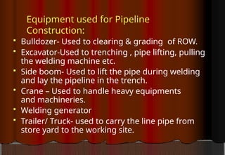
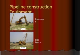
Equipment used forPipeline
Construction:
Bulldozer- Used to clearing & grading of ROW.
Excavator-Used to trenching , pipe lifting, pulling
the welding machine etc.
Side boom- Used to lift the pipe during welding
and lay the pipeline in the trench.
Crane – Used to handle heavy equipments
and machineries.
Welding generator
Trailer/ Truck- used to carry the line pipe from
store yard to the working site.
ROW Clearing &Grading
ROW is cleared of barriers and graded for
movement of construction equipment,
materials and ultimately construction of
pipeline.
23.
Pre Welding Activities
Welders test - an exam for the welders
before going to production weld.
Selection Criterion- Visual inspection & NDT
( API 1104)
PQR / WPS Test
-Tensile strength test
-Face bend test
-Root bend test
-Charpy V notch test
24.
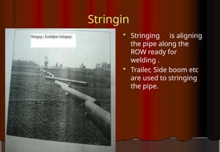
Stringin
g Stringingis aligning
the pipe along the
ROW ready for
welding .
Trailer, Side boom etc
are used to stringing
the pipe.
25.
Welding
Root pass/Stringer
pass
Hot pass
Filling pass
Cap Pass
Cleaning the welds
26.
NDT ( NonDestructive Test)
Dye penetrant test
Magnetic Particle test
Eddy current test
Radiographic test
Ultrasonic test
NDT personnel certification ( Level 1,2 &
3)
27.
NDT ( NonDestructive Test)
Radiography Test
o Equipment
o Method
o Source
o Film examination as Per API 1104
Standard
28.
NDT ( NonDestructive Test)
Ultrasonic Test
o Equipment
o Method
o Source
o Weld
examination
29.
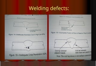
Common welding defects
Porosity
Cluster porosity
Slag inclusion
Lack of fusion
Lack of
penetration
Internal concavity
Burn through
Crack
Tie-in welds
Thefinal weld to join two separate
section together.
Should be properly aligned without
use of jacks or any external force.
Should be done within operating temp ( 5-
30 deg. Celsius).
NDT test.
33.
Roads and RailwayCrossing
Two different ways
Thrust boring/ Horizontal boring method
-Drill a hole under the roadway without
disturbing the road/ rail surface.
A casing pipe is placed through the hole and
then the pipeline is placed inside the casing.
Spacer is used to center the pipeline within
the casing pipe.
Open Cut method
34.
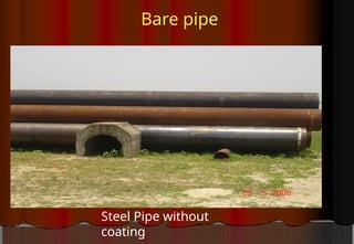
Pipe
Coating
All excepta portion ( about 6 inch ) of each pipe
is often coated in the factory before deliver to the
site.
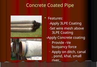
Three types of coating
-3LPE coating
-FBE coating
-Polyethylene coating
3LPE coating
-Apply adhesive on clean pipe surface
-Epoxy paint ( 40-100 micron)
-Polyethylene coating
Joint coating
Heatshrink sleeves
-Approx. 14 inch length and dia larger than pipe
dia.
-Shrink on applying heat and fitted to the pipe.
40.
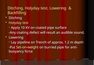
Ditching, Holyday test,Lowering &
Backfilling
Ditching
Holyday test
- Apply 10 KV on coated pipe surface
-Any coating defect will result an audible sound.
Lowering
- Lay pipeline on Trench of approx. 1.2 m depth
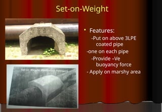
-Put Set-on-weight on burried pipe for anti-
buoyancy force
Hydro test
Aftermechanical completion of pipeline
Min test pressure should be 1.5 times of
design pressure.
Conventional hydro test pressure for high
pressure pipeline= 1.5 X 1135 psi = 1703 psi
Before commencing pressurization need to
obtain necessary permission from the
competent authority
.As per Gas Safety rules Department of
explosive is the competent authority in
Bangladesh.
Prior notification of testing should be given,
in writing to persons in the vicinity of the
pipeline .
45.
Hydro test (contd.)
Prior notification of testing should be given to
local police and other authorities, who may be
affected.
Warning notice stating “Warning-PipeLine
Under Test” and “No Parking” should be
placed at appropriate locations for the
duration of the test.
Patrols should be provided to watch special
points of hazard during the test, in particular
road, rail and water crossing and points of public
access.
Standby emergency crew should be available to
deal any unwanted situation.
46.
Commissioning
Prior tothe commissioning the pipeline should be
dry up.
Methods available for drying up are:
-Using dry air (compressor) push a series of
foam pigs through the pipeline collecting water
until the required dryness is achieved.
The pipeline should be purged of before
the admission of the gas to be
transmitted .
Use inert gas to purge of air.
After drying up a pipeline can be
commissioned straight to gas.
47.
Codes and Standards
ASME B31.8 ( Onshore & Offshore)
ASME B16.5 (Flange & Flange Fittings)
ASME B16.21 ( Gaskets for Flanges)
API 5L ( Line Pipe)
API 6D (Valves)
API 1104 (Welding Inspection)
ASME U- Stamp ( Pig Traps & Launcher)
ASME Boiler & Pressure Vessel Code ( Scrubber,
KOD and Other pressure Vessels)


![1) Pipeline Industry Overview [Autosaved].pptx](https://cdn.slidesharecdn.com/ss_thumbnails/1pipelineindustryoverviewautosaved-251217085734-68562f60-thumbnail.jpg?width=640&height=640&fit=bounds)


