Download as PDF, PPTX


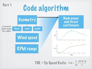


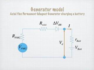
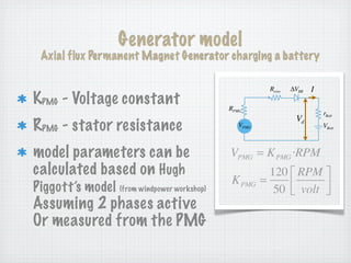
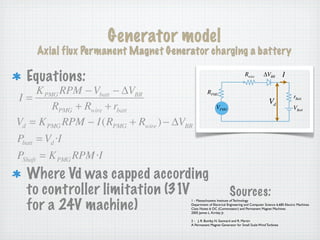


The document describes a Blade Element Momentum (BEM) model and battery charging generator model developed in Matlab to estimate electricity production and blade/tower loads for Hugh Piggott wind turbine designs. The model consists of a BEM code that uses turbine geometry and airfoil data to predict shaft power and blade loads, and a generator model that balances blade power with generator output. Test results show the model accurately estimates performance for one turbine design but less accurately for another, identifying areas for improvement. The open-source code and a future web interface are intended to help turbine designers evaluate and optimize their designs.


