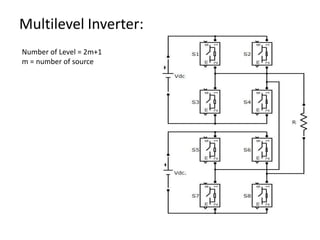
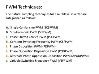
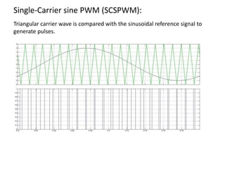
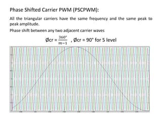
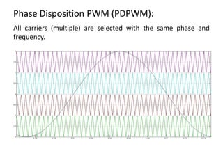
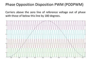
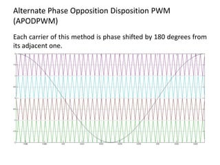
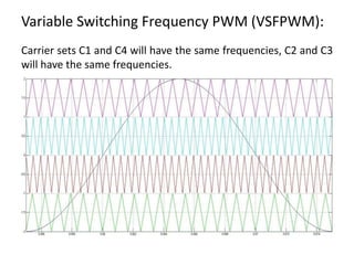
Harmonic comparisons of various
PWM techniques for basic MLI
By
MD SAQUIB MAQSOOD
M.Tech, PED
Multilevel Inverter:
Number of Level = 2m+1
m = number of source
PWM Techniques:
The natural sampling techniques for a multilevel inverter are
categorized as follows:
A. Single-Carrier sine PWM (SCSPWM)
B. Sub-Harmonic PWM (SHPWM)
a. Phase Shifted Carrier PWM (PSCPWM)
b. Constant Switching Frequency PWM (CSFPWM)
i. Phase Disposition PWM (PDPWM)
ii. Phase Opposition Disposition PWM (PODPWM)
iii. Alternate Phase Opposition Disposition PWM (APODPWM)
c. Variable Switching Frequency PWM (VSFPWM)
Single-Carrier sine PWM (SCSPWM):
Triangular carrier wave is compared with the sinusoidal reference signal to
generate pulses.
Phase Shifted Carrier PWM (PSCPWM):
All the triangular carriers have the same frequency and the same peak to
peak amplitude.
Phase shift between any two adjacent carrier waves
Øcr =
360°
𝑚−1
, Øcr = 90° for 5 level
Phase Disposition PWM (PDPWM):
All carriers (multiple) are selected with the same phase and
frequency.
Phase Opposition Disposition PWM (PODPWM)
Carriers above the zero line of reference voltage out of phase
with those of below this line by 180 degrees.
Alternate Phase Opposition Disposition PWM
(APODPWM)
Each carrier of this method is phase shifted by 180 degrees from
its adjacent one.
Variable Switching Frequency PWM (VSFPWM):
Carrier sets C1 and C4 will have the same frequencies, C2 and C3
will have the same frequencies.
Result:
PWM Techniques 3rd Harmonic % 5th Harmonic % THD % V01 volt
SCSPWM 0.81 0.36 67.12 91.96
PSCPWM 1.48 0.35 27.96 139.7
PDPWM 0.48 0.08 26.15 142.1
PODPWM 0.64 0.61 26.10 142
APODPWM 1.03 0.74 26.48 141.2
VSFPWM 0.51 0.21 26.33 141.2

Harmonic comparisons of various PWM techniques for basic MLI

  • 1.
    Harmonic comparisons ofvarious PWM techniques for basic MLI By MD SAQUIB MAQSOOD M.Tech, PED
  • 2.
    Multilevel Inverter: Number ofLevel = 2m+1 m = number of source
  • 3.
    PWM Techniques: The naturalsampling techniques for a multilevel inverter are categorized as follows: A. Single-Carrier sine PWM (SCSPWM) B. Sub-Harmonic PWM (SHPWM) a. Phase Shifted Carrier PWM (PSCPWM) b. Constant Switching Frequency PWM (CSFPWM) i. Phase Disposition PWM (PDPWM) ii. Phase Opposition Disposition PWM (PODPWM) iii. Alternate Phase Opposition Disposition PWM (APODPWM) c. Variable Switching Frequency PWM (VSFPWM)
  • 4.
    Single-Carrier sine PWM(SCSPWM): Triangular carrier wave is compared with the sinusoidal reference signal to generate pulses.
  • 5.
    Phase Shifted CarrierPWM (PSCPWM): All the triangular carriers have the same frequency and the same peak to peak amplitude. Phase shift between any two adjacent carrier waves Øcr = 360° 𝑚−1 , Øcr = 90° for 5 level
  • 6.
    Phase Disposition PWM(PDPWM): All carriers (multiple) are selected with the same phase and frequency.
  • 7.
    Phase Opposition DispositionPWM (PODPWM) Carriers above the zero line of reference voltage out of phase with those of below this line by 180 degrees.
  • 8.
    Alternate Phase OppositionDisposition PWM (APODPWM) Each carrier of this method is phase shifted by 180 degrees from its adjacent one.
  • 9.
    Variable Switching FrequencyPWM (VSFPWM): Carrier sets C1 and C4 will have the same frequencies, C2 and C3 will have the same frequencies.
  • 10.
    Result: PWM Techniques 3rdHarmonic % 5th Harmonic % THD % V01 volt SCSPWM 0.81 0.36 67.12 91.96 PSCPWM 1.48 0.35 27.96 139.7 PDPWM 0.48 0.08 26.15 142.1 PODPWM 0.64 0.61 26.10 142 APODPWM 1.03 0.74 26.48 141.2 VSFPWM 0.51 0.21 26.33 141.2