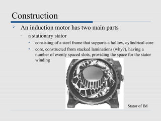
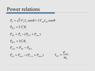
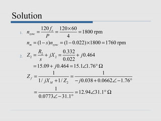
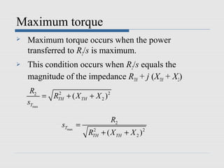
The motor is operating at full load with a slip of 4%.
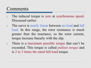
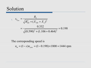
Determine:
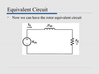
1. The rotor current
2. The rotor copper loss
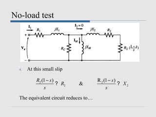
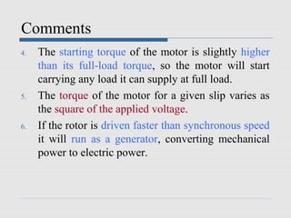
3. The air-gap power
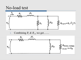
4. The efficiency
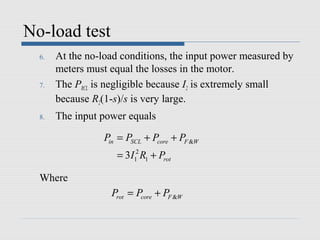
Solution:
Given:
V=460V, f=60Hz, P=25hp, Poles=4, R1=0.641Ω, R2=0.332Ω, X1=1.106Ω, Slip(s)=4%
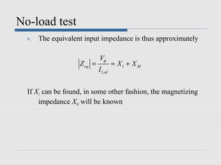
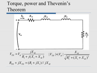
1. Rotor current
I2 = V/(R2 + jX2)
= 460/(0.332 + j1.106*0.04)
= 460/0.344
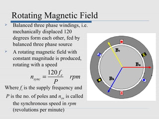

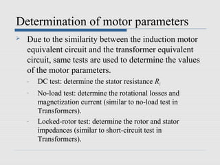
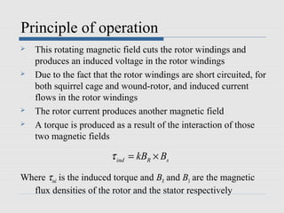
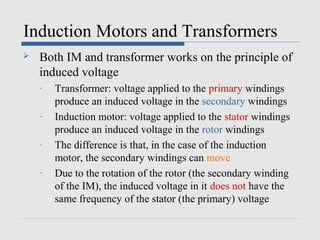
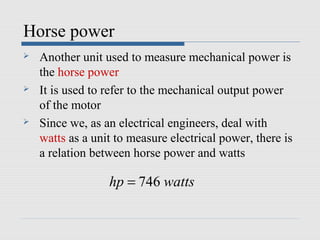
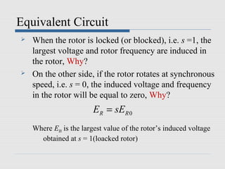
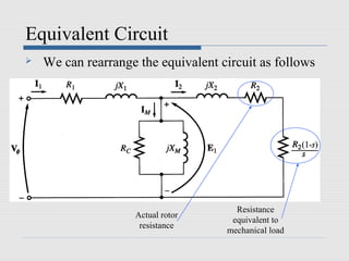
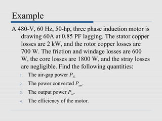
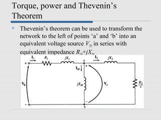
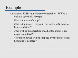
![Rotating Magnetic Field
Bnet (t ) = Ba (t ) + Bb (t ) + Bc (t )
= BM sin(ωt )∠0° + BM sin(ωt − 120°)∠120° + BM sin(ωt − 240)∠240°
= BM sin(ωt )x
ˆ
3
−[0.5 BM sin(ωt − 120°)]x − [
ˆ BM sin(ωt − 120°)]y
ˆ
2
3
−[0.5 BM sin(ωt − 240°)]x + [
ˆ BM sin(ωt − 240°)]yˆ
2](https://image.slidesharecdn.com/inductionmachines-130122023511-phpapp02/85/Induction-machines-11-320.jpg)
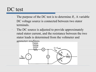
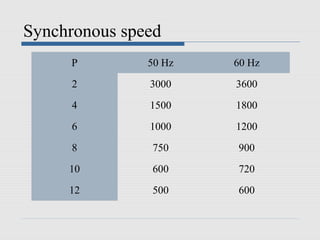
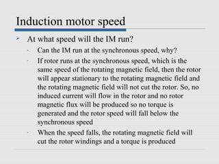
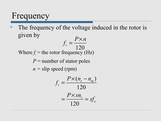
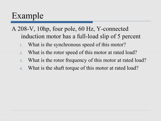
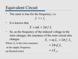
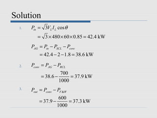
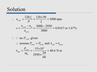
![Rotating Magnetic Field
1 3 1 3
Bnet (t ) = [ BM sin(ωt ) + BM sin(ωt ) + BM cos(ωt ) + BM sin(ωt ) − BM cos(ωt )]x
ˆ
4 4 4 4
3 3 3 3
+[ − BM sin(ωt ) − BM cos(ωt ) + BM sin(ωt ) − BM cos(ωt )]y
ˆ
4 4 4 4
= [1.5 BM sin(ωt )]x − [1.5BM cos(ωt )]y
ˆ ˆ](https://image.slidesharecdn.com/inductionmachines-130122023511-phpapp02/85/Induction-machines-12-320.jpg)
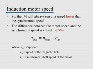
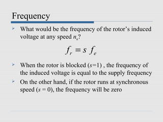
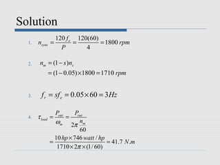
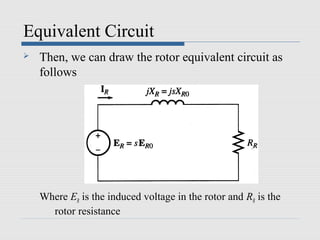
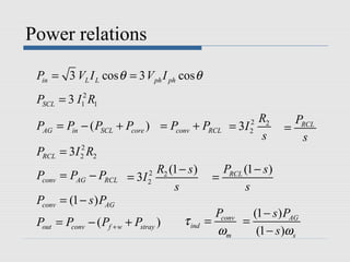
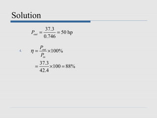
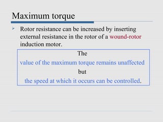

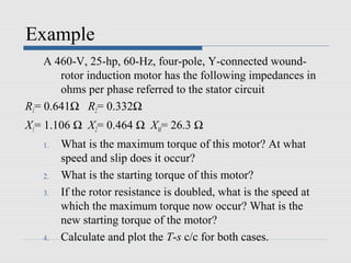
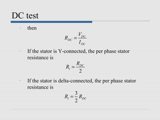
![Solution
The torque at this speed is
1 2
3VTH
τ max = ÷
2ωs R + R 2 + ( X + X )2 ÷
TH TH TH 2
3 × (255.2) 2
=
2π
2 × (1800 × )[0.590 + (0.590) 2 + (1.106 + 0.464) 2 ]
60
= 229 N.m](https://image.slidesharecdn.com/inductionmachines-130122023511-phpapp02/85/Induction-machines-64-320.jpg)
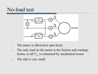
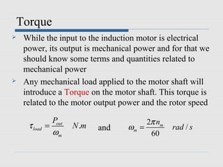
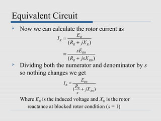
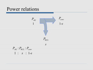
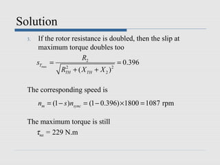
![Solution
2. The starting torque can be found from the torque eqn.
by substituting s = 1
2 R2
3VTH ÷
1 s
τ start = τ ind s =1 =
ωs R2
2
RTH + ÷ + ( X TH + X 2 ) 2
s s =1
2
3VTH R2
=
ωs [( RTH + R2 ) + ( X TH + X 2 ) 2 ]
2
3 × (255.2) 2 × (0.332)
=
2π
1800 × × [(0.590 + 0.332) 2 + (1.106 + 0.464) 2 ]
60
= 104 N.m](https://image.slidesharecdn.com/inductionmachines-130122023511-phpapp02/85/Induction-machines-65-320.jpg)
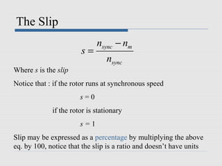
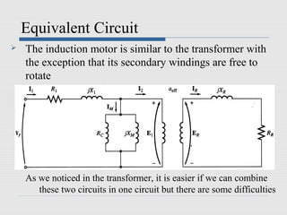
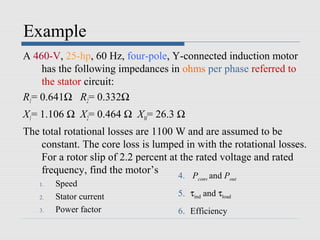
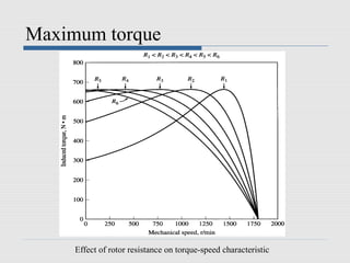
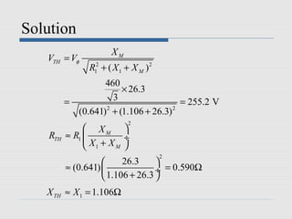
![Solution
The starting torque is now
3 × (255.2) 2 × (0.664)
τ start =
2π
1800 × × [(0.590 + 0.664) 2 + (1.106 + 0.464) 2 ]
60
= 170 N.m](https://image.slidesharecdn.com/inductionmachines-130122023511-phpapp02/85/Induction-machines-67-320.jpg)