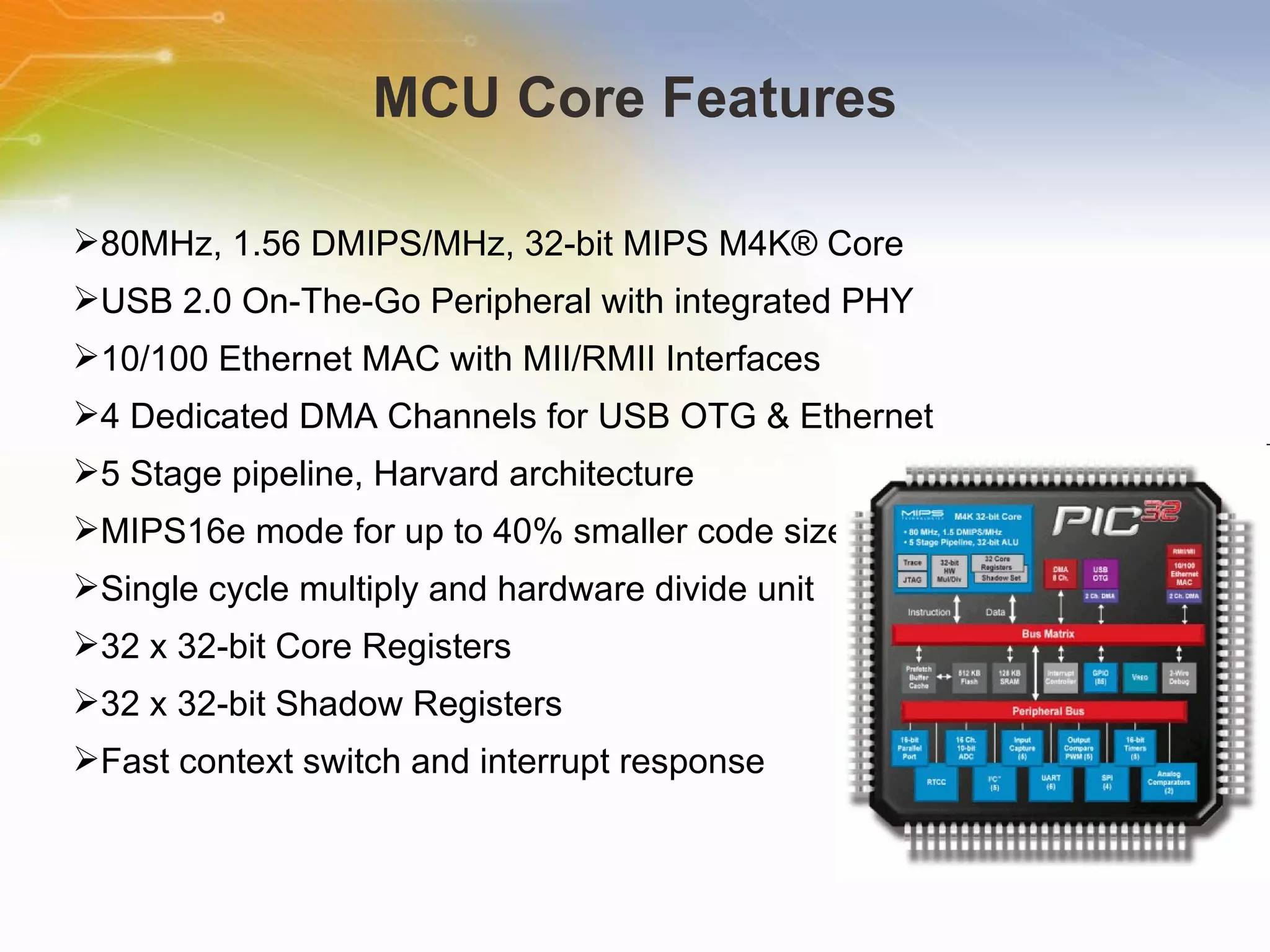
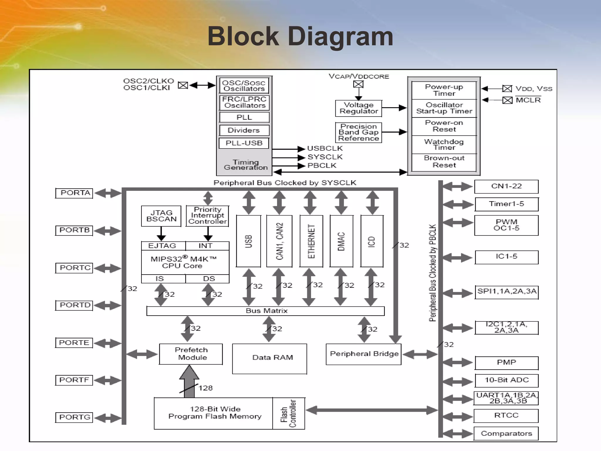
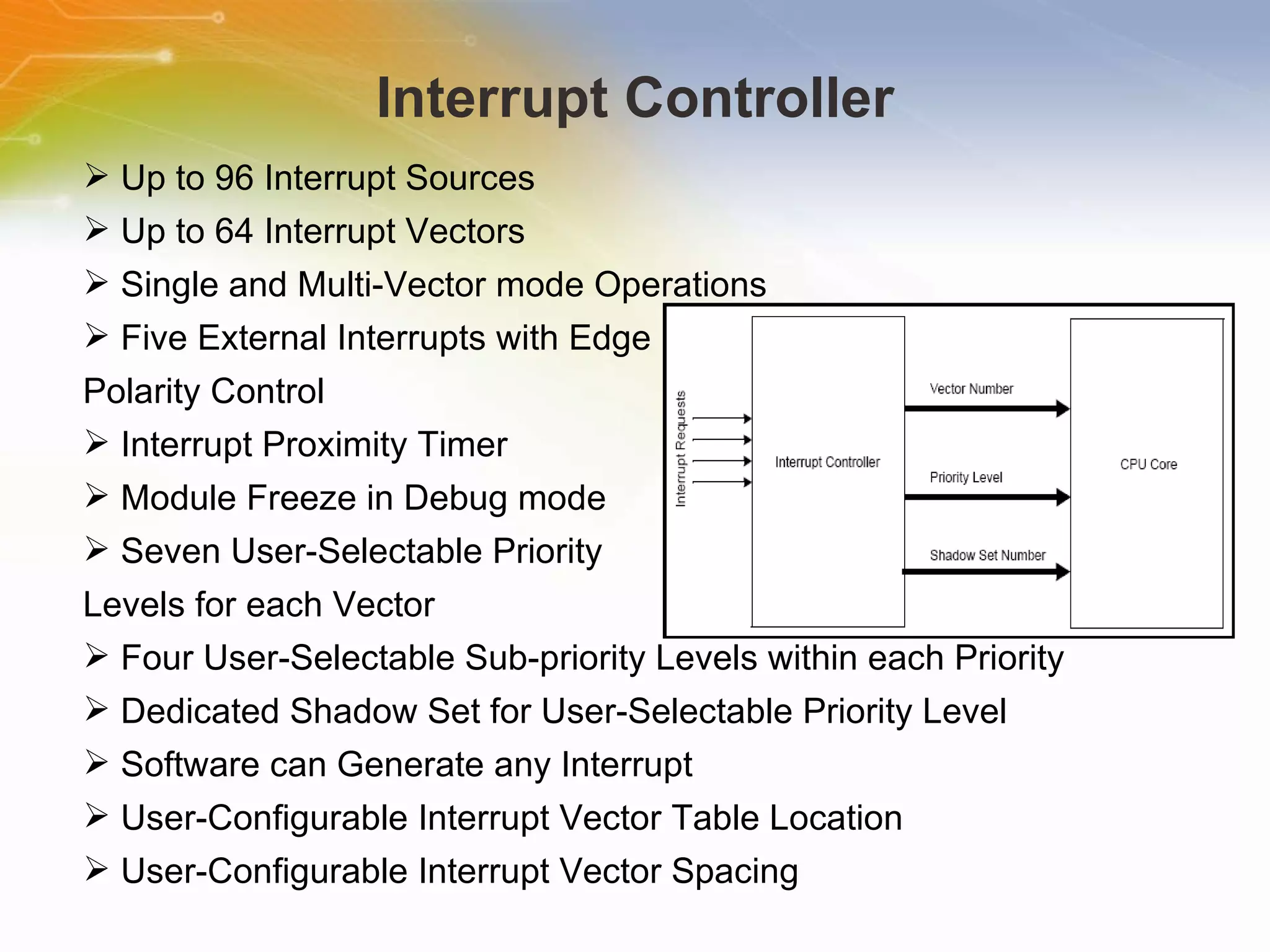
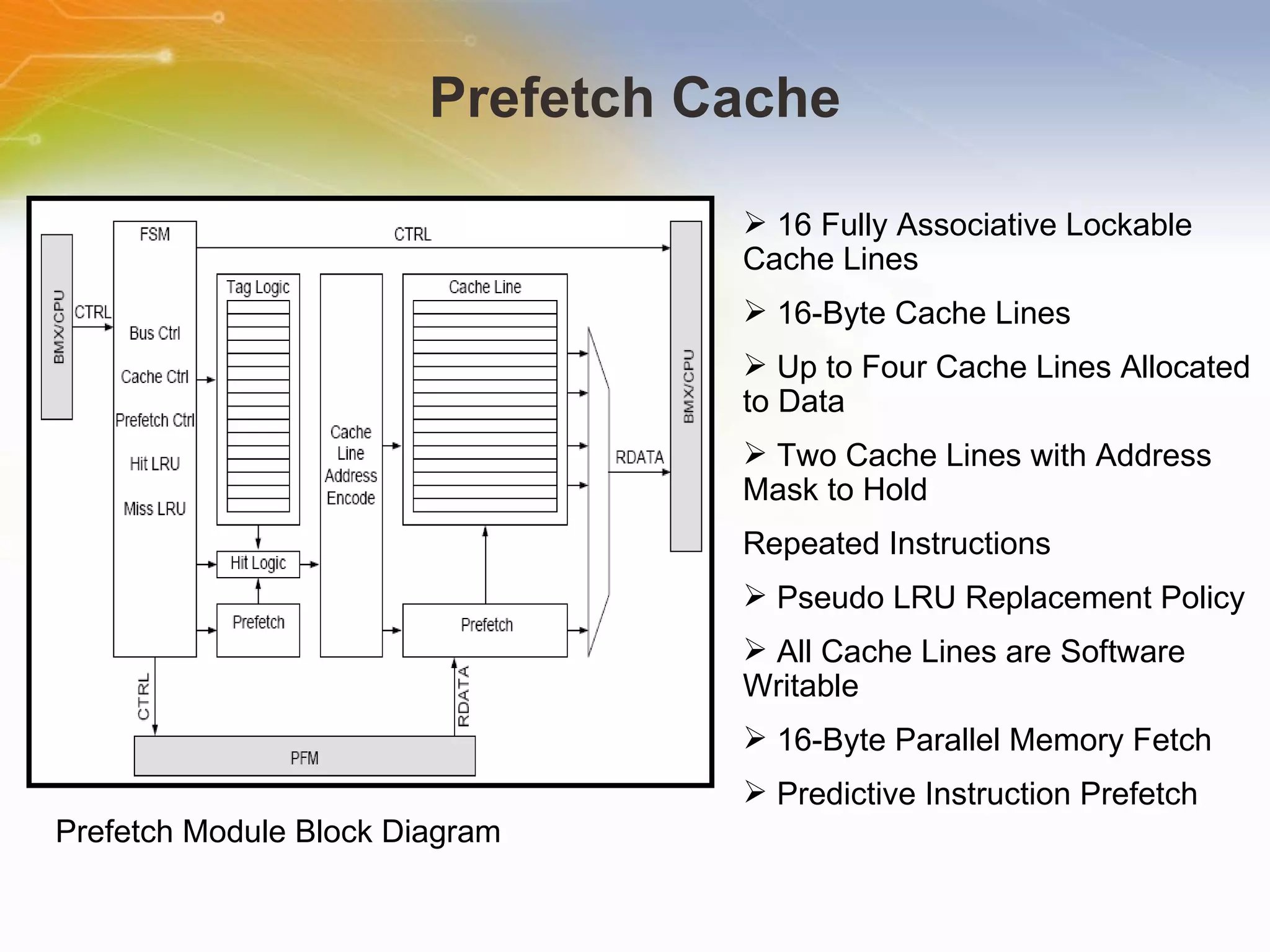
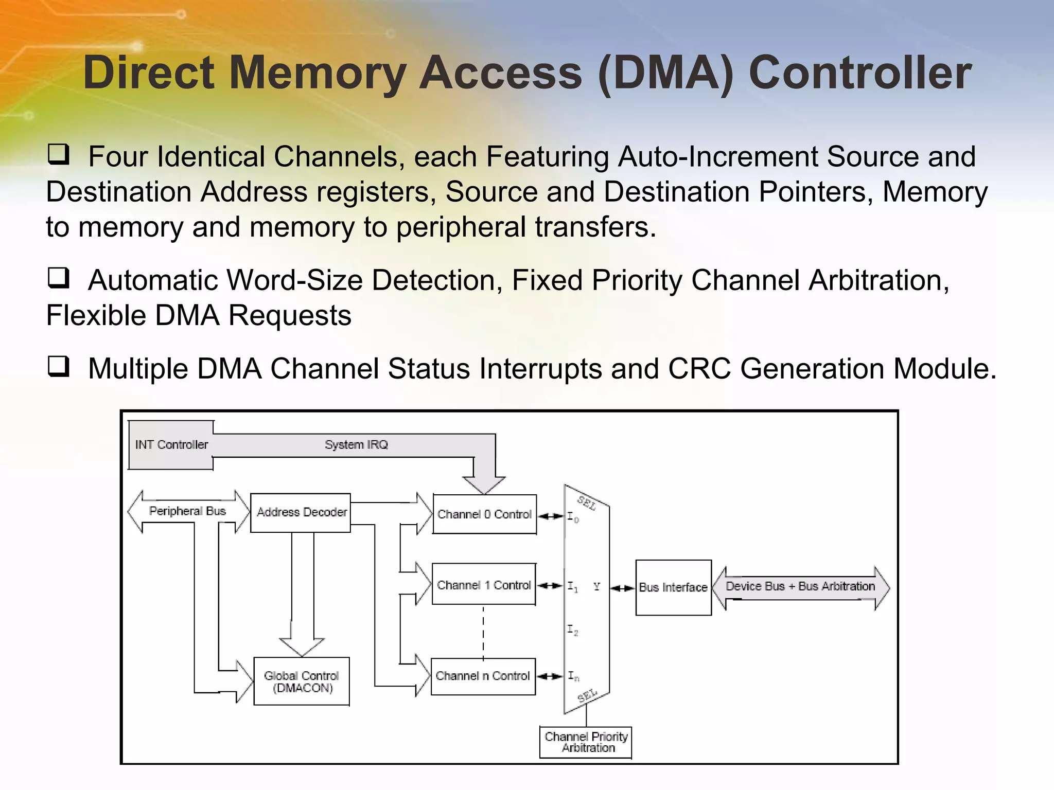
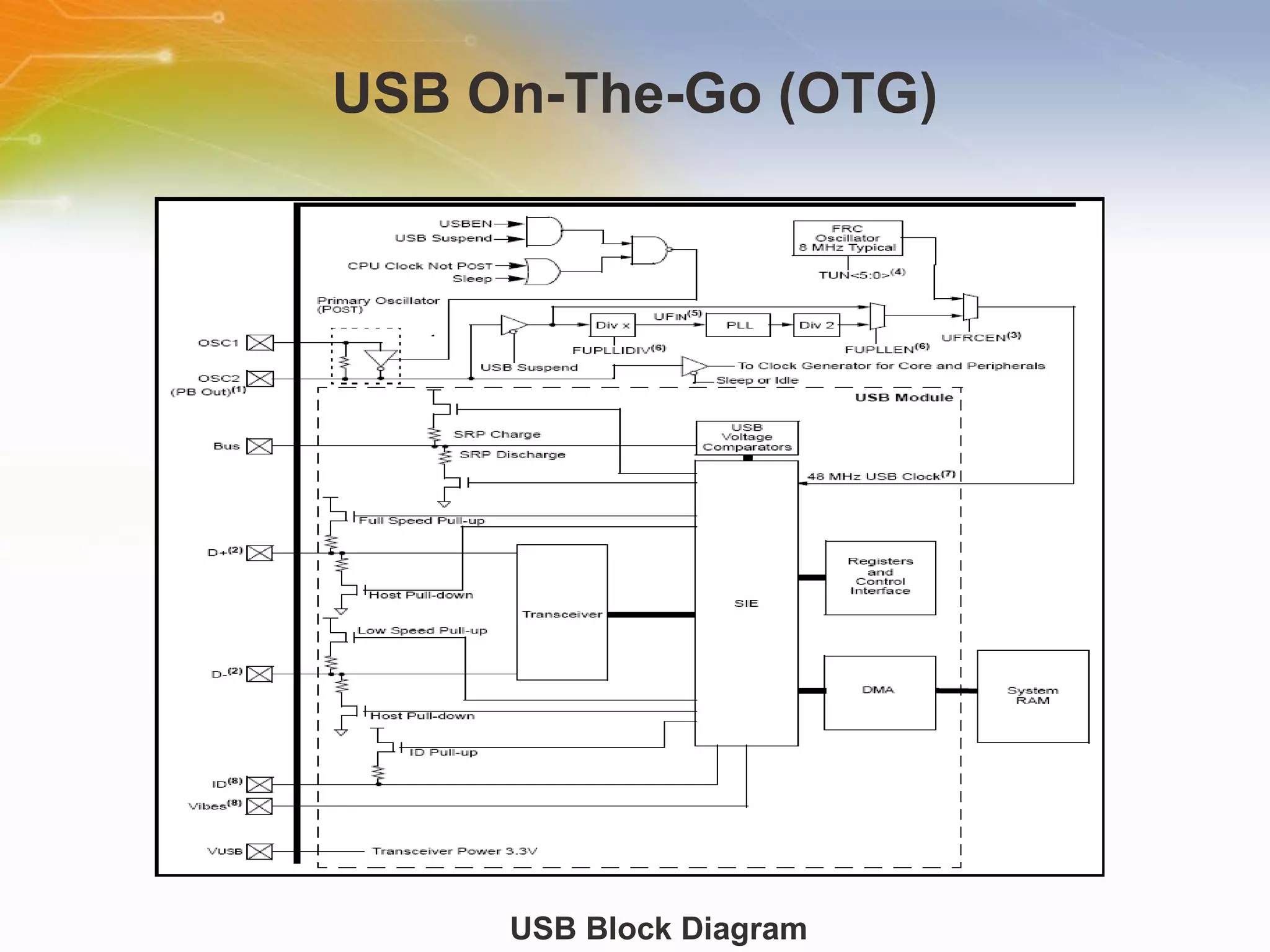
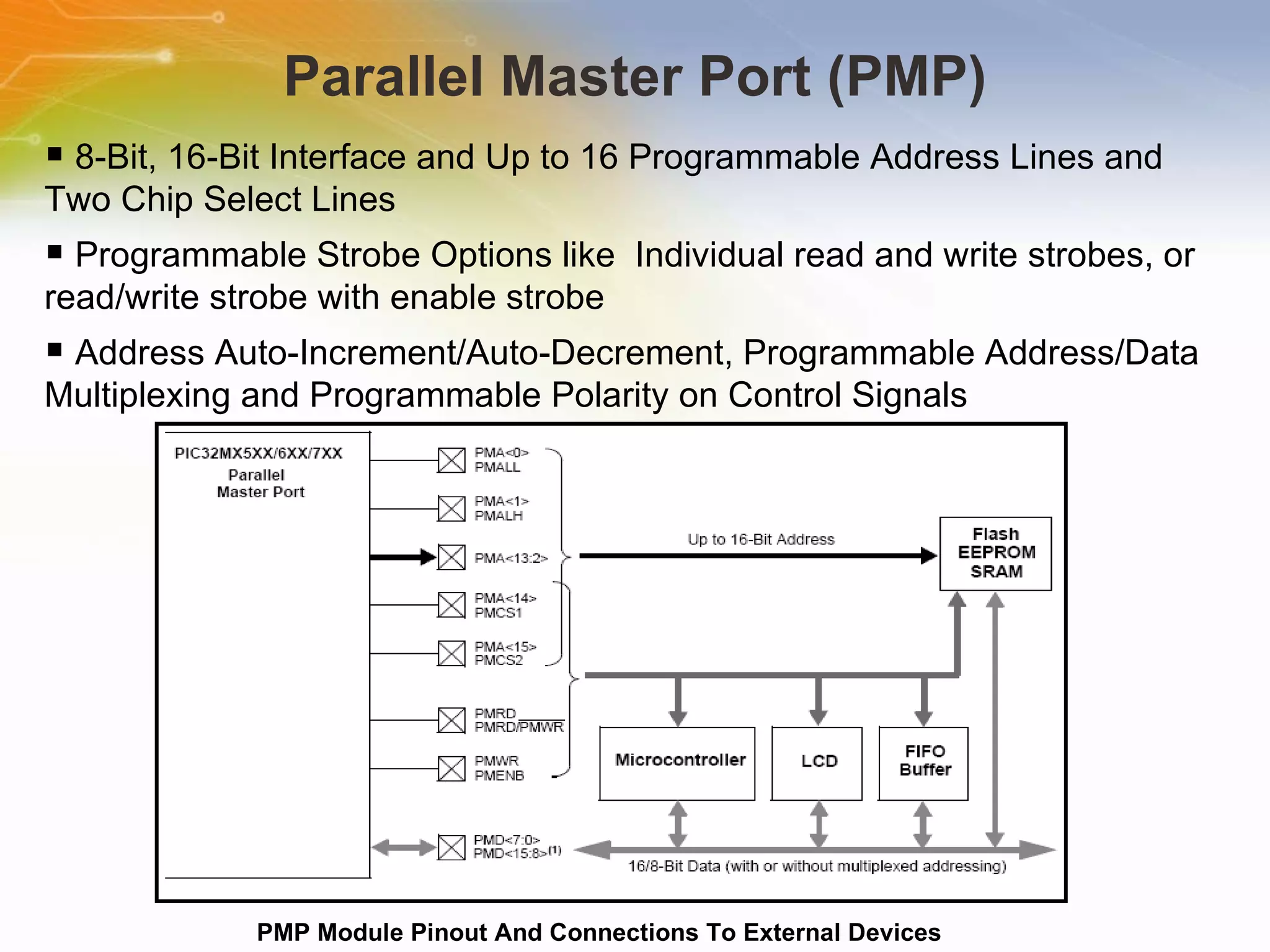
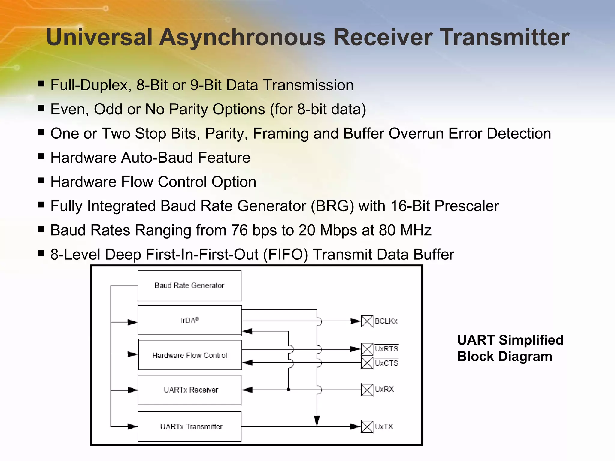
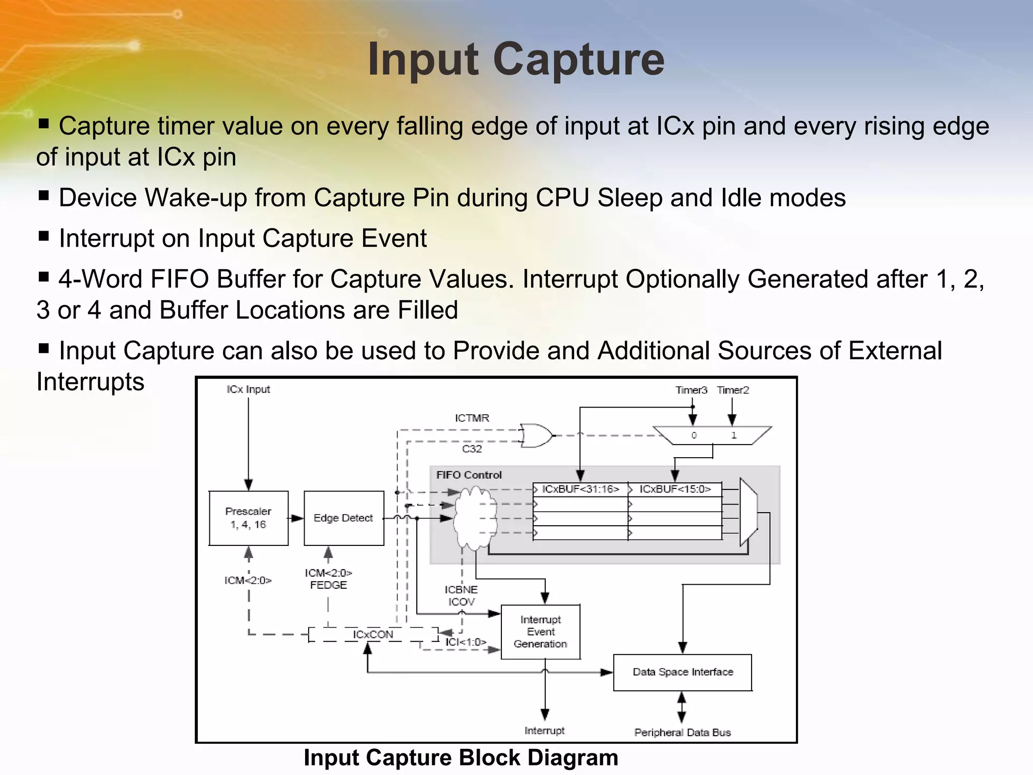
PIC32MX5XX/6XX/7XX USB, CAN and Ethernet 32-Bit Flash Microcontrollers Source: M ICROCHIP
Introduction Purpose An overview study on High-Performance, USB, CAN and Ethernet 32-Bit Flash Microcontrollers. Outline MCU and other Features Block Diagram and Memory Organisation Interrupt Controller, Pre-fetch Cache, DMA Controller USB, Ethernet Controller, Comparator ref voltage ADC, UART, CAN Features. Content 18 pages
MCU Core Features 80MHz, 1.56 DMIPS/MHz, 32-bit MIPS M4K® Core  USB 2.0 On-The-Go Peripheral with integrated PHY  10/100 Ethernet MAC with MII/RMII Interfaces  4 Dedicated DMA Channels for USB OTG & Ethernet  5 Stage pipeline, Harvard architecture  MIPS16e mode for up to 40% smaller code size  Single cycle multiply and hardware divide unit  32 x 32-bit Core Registers  32 x 32-bit Shadow Registers  Fast context switch and interrupt response
Other Features System   Features   512K   Flash   (plus   12K   boot   Flash)   64K   RAM   (can   execute   from   RAM)   8   Channel   General   Hardware   DMA   Controller   Flash   pre-Fetch   module   with   256   Byte   cache   Lock   instructions   or   data   in   cache   for   fast   access   Programmable   vector   interrupt   controller Analog   Features   Fast   and   Accurate   16   channel   10-bit   ADC,   Max   1   Mega   sample   per   second   at   +/-   1LSB,   conversion   available   during   SLEEP   &   IDLE
Block Diagram
Memory Organization 32-bit native data width Separate User (KUSEG) and Kernel (KSEG0/KSEG1) mode address space Flexible program Flash memory partitioning Flexible data RAM partitioning for data and program space Separate boot Flash memory for protected code Robust bus exception handling to intercept runaway code Simple memory mapping with Fixed Mapping Translation (FMT) unit Cacheable (KSEG0) and non-cacheable (KSEG1) address regions
Interrupt Controller Up to 96 Interrupt Sources Up to 64 Interrupt Vectors Single and Multi-Vector mode Operations Five External Interrupts with Edge Polarity Control Interrupt Proximity Timer Module Freeze in Debug mode Seven User-Selectable Priority  Levels for each Vector Four User-Selectable Sub-priority Levels within each Priority Dedicated Shadow Set for User-Selectable Priority Level Software can Generate any Interrupt User-Configurable Interrupt Vector Table Location User-Configurable Interrupt Vector Spacing
Prefetch Cache Prefetch Module Block Diagram 16 Fully Associative Lockable Cache Lines 16-Byte Cache Lines Up to Four Cache Lines Allocated to Data Two Cache Lines with Address Mask to Hold Repeated Instructions Pseudo LRU Replacement Policy All Cache Lines are Software Writable 16-Byte Parallel Memory Fetch Predictive Instruction Prefetch
Direct Memory Access (DMA) Controller Four Identical Channels, each Featuring Auto-Increment Source and Destination Address registers, Source and Destination Pointers, Memory to memory and memory to peripheral transfers. Automatic Word-Size Detection, Fixed Priority Channel Arbitration, Flexible DMA Requests Multiple DMA Channel Status Interrupts and CRC Generation Module.
USB On-The-Go (OTG) USB Block Diagram
Comparator Voltage Reference (CVREF) •  High and low range selection •  Sixteen output levels available for each range •  Internally connected to comparators to conserve device pins •  Output can be connected to a pin
Ethernet Controller Ethernet Controller Block Diagram
Controller Area Network (CAN) PIC32MX CAN Module Block Diagram
10-BIT ANALOG-TO-DIGITAL CONVERTER (ADC) Successive Approximation Register (SAR) Conversion Up to 1 Msps Conversion Speed and  Up to 16 Analog Input Pins External Voltage Reference Input Pins Automatic Channel Scan mode 16-word Conversion Result Buffer
Parallel Master Port (PMP) 8-Bit, 16-Bit Interface and Up to 16 Programmable Address Lines and Two Chip Select Lines Programmable Strobe Options like  Individual read and write strobes, or read/write strobe with enable strobe Address Auto-Increment/Auto-Decrement, Programmable Address/Data Multiplexing and Programmable Polarity on Control Signals PMP Module Pinout And Connections To External Devices
Universal Asynchronous Receiver Transmitter Full-Duplex, 8-Bit or 9-Bit Data Transmission Even, Odd or No Parity Options (for 8-bit data) One or Two Stop Bits, Parity, Framing and Buffer Overrun Error Detection Hardware Auto-Baud Feature Hardware Flow Control Option Fully Integrated Baud Rate Generator (BRG) with 16-Bit Prescaler Baud Rates Ranging from 76 bps to 20 Mbps at 80 MHz 8-Level Deep First-In-First-Out (FIFO) Transmit Data Buffer UART Simplified Block Diagram
Input Capture Input Capture Block Diagram Capture timer value on every falling edge of input at ICx pin and every rising edge of input at ICx pin Device Wake-up from Capture Pin during CPU Sleep and Idle modes Interrupt on Input Capture Event 4-Word FIFO Buffer for Capture Values. Interrupt Optionally Generated after 1, 2, 3 or 4 and Buffer Locations are Filled Input Capture can also be used to Provide and Additional Sources of External Interrupts
Additional Resource For ordering  PIC32MX5xx/6xx/7xx , please click the part list or Call our sales hotline For more product information go to http://www.microchip.com/wwwproducts/Devices.aspx?dDocName=en547140#1 Visit Element 14 to post your question   www.element-14.com For additional inquires contact our technical service hotline or even use our “Live Technical Chat” online facility Newark Farnell

PIC32MX5XX/6XX/7XX USB, CAN and Ethernet 32-Bit Flash Microcontrollers

  • 1.
    PIC32MX5XX/6XX/7XX USB, CANand Ethernet 32-Bit Flash Microcontrollers Source: M ICROCHIP
  • 2.
    Introduction Purpose Anoverview study on High-Performance, USB, CAN and Ethernet 32-Bit Flash Microcontrollers. Outline MCU and other Features Block Diagram and Memory Organisation Interrupt Controller, Pre-fetch Cache, DMA Controller USB, Ethernet Controller, Comparator ref voltage ADC, UART, CAN Features. Content 18 pages
  • 3.
    MCU Core Features80MHz, 1.56 DMIPS/MHz, 32-bit MIPS M4K® Core USB 2.0 On-The-Go Peripheral with integrated PHY 10/100 Ethernet MAC with MII/RMII Interfaces 4 Dedicated DMA Channels for USB OTG & Ethernet 5 Stage pipeline, Harvard architecture MIPS16e mode for up to 40% smaller code size Single cycle multiply and hardware divide unit 32 x 32-bit Core Registers 32 x 32-bit Shadow Registers Fast context switch and interrupt response
  • 4.
    Other Features System Features 512K Flash (plus 12K boot Flash) 64K RAM (can execute from RAM) 8 Channel General Hardware DMA Controller Flash pre-Fetch module with 256 Byte cache Lock instructions or data in cache for fast access Programmable vector interrupt controller Analog Features Fast and Accurate 16 channel 10-bit ADC, Max 1 Mega sample per second at +/- 1LSB, conversion available during SLEEP & IDLE
  • 5.
  • 6.
    Memory Organization 32-bitnative data width Separate User (KUSEG) and Kernel (KSEG0/KSEG1) mode address space Flexible program Flash memory partitioning Flexible data RAM partitioning for data and program space Separate boot Flash memory for protected code Robust bus exception handling to intercept runaway code Simple memory mapping with Fixed Mapping Translation (FMT) unit Cacheable (KSEG0) and non-cacheable (KSEG1) address regions
  • 7.
    Interrupt Controller Upto 96 Interrupt Sources Up to 64 Interrupt Vectors Single and Multi-Vector mode Operations Five External Interrupts with Edge Polarity Control Interrupt Proximity Timer Module Freeze in Debug mode Seven User-Selectable Priority Levels for each Vector Four User-Selectable Sub-priority Levels within each Priority Dedicated Shadow Set for User-Selectable Priority Level Software can Generate any Interrupt User-Configurable Interrupt Vector Table Location User-Configurable Interrupt Vector Spacing
  • 8.
    Prefetch Cache PrefetchModule Block Diagram 16 Fully Associative Lockable Cache Lines 16-Byte Cache Lines Up to Four Cache Lines Allocated to Data Two Cache Lines with Address Mask to Hold Repeated Instructions Pseudo LRU Replacement Policy All Cache Lines are Software Writable 16-Byte Parallel Memory Fetch Predictive Instruction Prefetch
  • 9.
    Direct Memory Access(DMA) Controller Four Identical Channels, each Featuring Auto-Increment Source and Destination Address registers, Source and Destination Pointers, Memory to memory and memory to peripheral transfers. Automatic Word-Size Detection, Fixed Priority Channel Arbitration, Flexible DMA Requests Multiple DMA Channel Status Interrupts and CRC Generation Module.
  • 10.
    USB On-The-Go (OTG)USB Block Diagram
  • 11.
    Comparator Voltage Reference(CVREF) • High and low range selection • Sixteen output levels available for each range • Internally connected to comparators to conserve device pins • Output can be connected to a pin
  • 12.
    Ethernet Controller EthernetController Block Diagram
  • 13.
    Controller Area Network(CAN) PIC32MX CAN Module Block Diagram
  • 14.
    10-BIT ANALOG-TO-DIGITAL CONVERTER(ADC) Successive Approximation Register (SAR) Conversion Up to 1 Msps Conversion Speed and Up to 16 Analog Input Pins External Voltage Reference Input Pins Automatic Channel Scan mode 16-word Conversion Result Buffer
  • 15.
    Parallel Master Port(PMP) 8-Bit, 16-Bit Interface and Up to 16 Programmable Address Lines and Two Chip Select Lines Programmable Strobe Options like Individual read and write strobes, or read/write strobe with enable strobe Address Auto-Increment/Auto-Decrement, Programmable Address/Data Multiplexing and Programmable Polarity on Control Signals PMP Module Pinout And Connections To External Devices
  • 16.
    Universal Asynchronous ReceiverTransmitter Full-Duplex, 8-Bit or 9-Bit Data Transmission Even, Odd or No Parity Options (for 8-bit data) One or Two Stop Bits, Parity, Framing and Buffer Overrun Error Detection Hardware Auto-Baud Feature Hardware Flow Control Option Fully Integrated Baud Rate Generator (BRG) with 16-Bit Prescaler Baud Rates Ranging from 76 bps to 20 Mbps at 80 MHz 8-Level Deep First-In-First-Out (FIFO) Transmit Data Buffer UART Simplified Block Diagram
  • 17.
    Input Capture InputCapture Block Diagram Capture timer value on every falling edge of input at ICx pin and every rising edge of input at ICx pin Device Wake-up from Capture Pin during CPU Sleep and Idle modes Interrupt on Input Capture Event 4-Word FIFO Buffer for Capture Values. Interrupt Optionally Generated after 1, 2, 3 or 4 and Buffer Locations are Filled Input Capture can also be used to Provide and Additional Sources of External Interrupts
  • 18.
    Additional Resource Forordering PIC32MX5xx/6xx/7xx , please click the part list or Call our sales hotline For more product information go to http://www.microchip.com/wwwproducts/Devices.aspx?dDocName=en547140#1 Visit Element 14 to post your question www.element-14.com For additional inquires contact our technical service hotline or even use our “Live Technical Chat” online facility Newark Farnell