SlideShare a Scribd company logo
1 of 44
Download to read offline
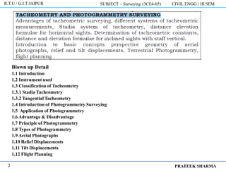
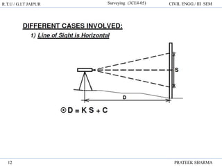
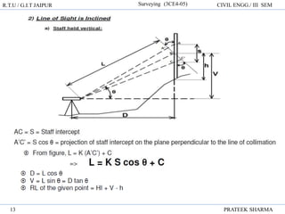
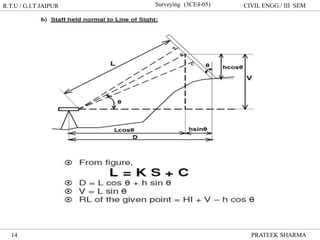
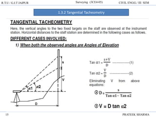
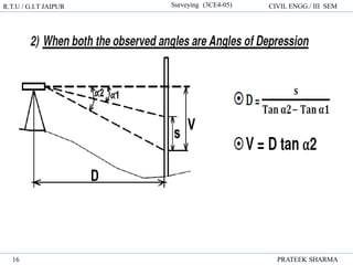
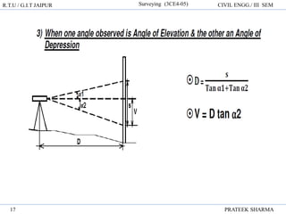
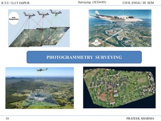
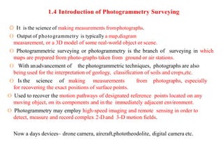
UNIT – 4
TACHEOMETRY AND PHOTOGRAMMETRY
SURVEYING
R.T.U / G.I.T JAIPUR SUBJECT – Surveying (3CE4-05) CIVIL ENGG./ III SEM
PRATEEK SHARMA
1
Blown up Detail
1.1 Introduction
1.2 Instrument used
1.3 Classification of Tacheometry
1.3.1 Stadia Tacheometry
1.3.2 Tangential Tacheometry
1.4 Introduction of Photogrammetry Surveying
1.5 Application of Photogrammetry
1.6 Advantage & Disadvantage
1.7 Principle of Photogrammetry
1.8 Types of Photogrammetry
1.9 Aerial Photographs
1.10 Relief Displacements
1.11 Tilt Displacements
1.12 Flight Planning
R.T.U / G.I.T JAIPUR SUBJECT – Surveying (3CE4-05) CIVIL ENGG./ III SEM
PRATEEK SHARMA
2
1.1 Introduction
• Tacheometry is the branch of survey in which the horizontal and vertical distances of
points are obtained by instrumental observations such as staff intercepts and angles.
– The process of measuring horizontal distance is eliminated
– Less accurate, but more rapid
– Best useful in case of rough & difficult terrain
– Primary objective is preparation of contour maps or plans
– Used in Hydrographic surveys, location surveys etc.
R.T.U / G.I.T JAIPUR Surveying (3CE4-05) CIVIL ENGG./ III SEM
PRATEEK SHARMA
3
R.T.U / G.I.T JAIPUR Surveying (3CE4-05) CIVIL ENGG./ III SEM
PRATEEK SHARMA
4
1.2 Instruments used in Tacheometry are:
Tacheometer – A transit Theodolite fitted with a stadia diaphragm
Diaphragm is the frame upon which is mounted the crosshairs to give a definite line
of sight.
Stadia hairs / Stadia Lines are a pair of horizontal hairs provided in addition to the
regular crosshairs. Each on of this is equidistant from the central horizontal hair.
Commonly used Stadia diaphragms are shown here.
R.T.U / G.I.T JAIPUR Surveying (3CE4-05) CIVIL ENGG./ III SEM
PRATEEK SHARMA
5
Levelling Staff / Stadia Rod – a scale, shown below, graduated in metres and
centimeters. They may be single solid, folding or telescopic.
R.T.U / G.I.T JAIPUR Surveying (3CE4-05) CIVIL ENGG./ III SEM
PRATEEK SHARMA
6
Important Terminology
•Stadia Interval (i)– the actual physical distance between the top & bottom stadia hairs
•Staff intercept (S) – the difference between the leveling staff readings corresponding to
the top & bottom stadia hairs
R.T.U / G.I.T JAIPUR Surveying (3CE4-05) CIVIL ENGG./ III SEM
PRATEEK SHARMA
7
1.3 CLASSIFICATION OF TACHEOMETRY – based on the underlying principle
1) Stadia Tacheometry – make use of stadia hairs. Involves observation of either staff
intercepts or stadia intervals.
a.Fixed Hair method –
• Stadia hairs are stationary => Stadia interval (i) is constant
• Staff intercept depends upon the horizontal distance between the
tacheometer and stadia rod => Staff intercept (S) is variable
• Most commonly used
b. Movable Hair method –
• Here, the stadia rod or leveling staff is provided with two fixed targets.
The stadia hairs can be moved to coincide the targets accurately, using
micrometer screws => Stadia interval (i) is variable
• Since the same staff with fixed targets is used
everywhere => Staff intercept (S) is constant
• Rarely used
2) Tangential Tacheometry – does not use stadia hairs, hence stadia diaphragm is
not required. Here, a transit Theodolite is used to measure vertical angles to the
two fixed targets on a staff held at a station point.
R.T.U / G.I.T JAIPUR Surveying (3CE4-05) CIVIL ENGG./ III SEM
PRATEEK SHARMA
8
1.3.1 Stadia Tacheometry
R.T.U / G.I.T JAIPUR Surveying (3CE4-05) CIVIL ENGG./ III SEM
PRATEEK SHARMA
9
1.3.1 Stadia Tacheometry
R.T.U / G.I.T JAIPUR Surveying (3CE4-05) CIVIL ENGG./ III SEM
PRATEEK SHARMA
10
R.T.U / G.I.T JAIPUR Surveying (3CE4-05) CIVIL ENGG./ III SEM
PRATEEK SHARMA
11
R.T.U / G.I.T JAIPUR Surveying (3CE4-05) CIVIL ENGG./ III SEM
PRATEEK SHARMA
12
R.T.U / G.I.T JAIPUR Surveying (3CE4-05) CIVIL ENGG./ III SEM
PRATEEK SHARMA
13
R.T.U / G.I.T JAIPUR Surveying (3CE4-05) CIVIL ENGG./ III SEM
PRATEEK SHARMA
14
R.T.U / G.I.T JAIPUR Surveying (3CE4-05) CIVIL ENGG./ III SEM
PRATEEK SHARMA
15
1.3.2 Tangential Tacheometry
R.T.U / G.I.T JAIPUR Surveying (3CE4-05) CIVIL ENGG./ III SEM
PRATEEK SHARMA
16
R.T.U / G.I.T JAIPUR Surveying (3CE4-05) CIVIL ENGG./ III SEM
PRATEEK SHARMA
17
R.T.U / G.I.T JAIPUR Surveying (3CE4-05) CIVIL ENGG./ III SEM
PRATEEK SHARMA
18
PHOTOGRAMMETRY SURVEYING
1.4 Introduction of Photogrammetry Surveying
O It is the science of making measurements fromphotographs.
O Output of photogrammetry is typically a map,diagram
measurement, or a 3D model of some real-world object or scene.
O Photogrammetric surveying or photogrammetry is the branch of surveying in which
maps are prepared from photo-graphs taken from ground or air stations.
O With anadvancement of the photogrammetric techniques, photographs are also
being used for the interpretation of geology, classification of soils and crops,etc.
O Is the science of making measurements from photographs, especially
for recovering the exact positions of surface points.
O Used to recover the motion pathways of designated reference points located on any
moving object, on its components and in the immediately adjacent environment.
O Photogrammetry may employ high-speed imaging and remote sensing in order to
detect, measure and record complex 2-D and 3-D motion fields.
Now a days devices– drone camera, aircraft,phototheodolite, digital camera etc.
R.T.U / G.I.T JAIPUR Surveying (3CE4-05) CIVIL ENGG./ III SEM
PRATEEK SHARMA
20
• Photogrammetry is traditionally used to create topographic maps from aerial and
spatial imagery. Close range photogrammetry is also used at the School
of Surveying to obtain accurate measurements of animals in wildlife research or to
create virtual models of historical buildings.
• The fundamental principle used by photogrammetry is triangulation. By taking
photographs from at least two different locations, so-called “lines of sight” can be
developed from each camera to points on the object.
• Photogrammetry is used in fields such as topographic mapping, architecture,
engineering, manufacturing, quality control, police investigation, cultural heritage,
and geology.
R.T.U / G.I.T JAIPUR Surveying (3CE4-05) CIVIL ENGG./ III SEM
PRATEEK SHARMA
21
• At 1 part in 30,000 on a 3m object, point positions would be accurate to 0.1mm at
68% probability (one sigma). This is relative accuracy. To find the
absolute accuracy the project must be scaled and or have control points defined.
Then the accuracy of these scales and control points affect the absolute accuracy.
• In 1849, Aimé Laussedat (April 19, 1819 - March 18, 1907) was the first person to
use terrestrial photographs for topographic map compilation. He is referred to as the
"Father of Photogrammetry".
R.T.U / G.I.T JAIPUR Surveying (3CE4-05) CIVIL ENGG./ III SEM
PRATEEK SHARMA
22
• Photogrammetry is the science and technology of obtaining reliable information
about physical objects and the environment through the process of recording,
measuring and interpreting photographic images and patterns of electromagnetic
radiant imagery and other phenomena.
• Photogrammetry appeared in the middle of the 19th century, almost simultaneously
with the appearance of photography itself. The use of photographs to
create topographic maps was first proposed by the French surveyor Dominique F.
Arago in about 1840.
• The term photogrammetry was coined by the Prussian architect Albrecht
Meydenbauer, which appeared his 1867 article "Die Photometrographie."
• There are many variants of photogrammetry. One example is the extraction of
three-dimensional measurements from two-dimensional data (i.e. images); for
example, the distance between two points that lie on a plane parallel to the
photographic image plane can be determined by measuring their distance on the
image, if the scale of the image is known. Another is the extraction of
accurate color ranges and values representing such quantities as albedo, specular
reflection, metallicity, or ambient occlusion from photographs of materials for the
purposes of physically based rendering.
R.T.U / G.I.T JAIPUR Surveying (3CE4-05) CIVIL ENGG./ III SEM
PRATEEK SHARMA
23
• Broadly Photogrammetry Requires:
• Planning & taking the photographs
• Processing the photographs
• Measuring the photographs & Reducing
• the measurement to produce end results.
• Field Application of Photogrammetry :
• Used to conduct topographical survey or engineering surveys.
• Suitable for mountainous and hilly terrain with little vegetation.
• Used for geological mapping which includes identification of land forms, rock type
& rock structures.
• Used for projects demanding higher accuracy, since it provides
• accurate measurements.
• Used in urban and regional planning applications.
• Used mostly in Planning/designing in transport planning, bridge,
• pipeline, hydropower, urban planning, security and strategic
• planning, disaster management, natural resources management, city
• models, conservation of archaeological sites etc.
1.5 Application of Photogrammetry
• Importance/application of photogrammetry
• Its applications include satellite tracking of the relative positioning alterations in all
Earth environments.
• The quantitative results of photogrammetry are used to guide and match the results of
computational models of the natural systems, thus helping to invalidate or confirm new
theories, to design novel vehicles or new methods for predicting or/and controlling the
consequences of earthquakes, tsunamis, any weather types.
• Photogrammetry also helps for the solving of triangulation, trilateration and
multidimensional scaling.
• In the simplest example, the distance between two points that lie on a plane parallel to
the photographic image plane can be determined by measuring their distance on the
image, if the scale (s) of the image is known.
R.T.U / G.I.T JAIPUR Surveying (3CE4-05) CIVIL ENGG./ III SEM
PRATEEK SHARMA
24
R.T.U / G.I.T JAIPUR Surveying (3CE4-05) CIVIL ENGG./ III SEM
PRATEEK SHARMA
25
1.6 Advantage & Disadvantage
• Used in different fields, such as topographic mapping, architecture, engineering,
manufacturing, quality control, police investigation, and geology, as well as by
archaeologists to quickly produce plans of large or complex sites and by
meteorologists.
• Principle of photogrammetric survey in its simplest form is very similar to that of the
plane table survey.
• Only difference is that the most of the work which in plane table survey is executed in
the field, but here is done in office.
• The principal point of each photograph is used as a fixed station and rays are drawn to
get points of intersections very similar to those used in plane table.
• Is suitable for topographical or engineering surveys and also for those projects
demanding higher accuracy.
• It is unsuitable for dense forest & others due to the difficulty of identifying points upon
the pair of photographs.
R.T.U / G.I.T JAIPUR Surveying (3CE4-05) CIVIL ENGG./ III SEM
PRATEEK SHARMA
26
1.7 PRINCIPLE OF PHOTOGRAMMETRY
• The photographs used in photogrammetry may be broadly classified into two types
depending upon the camera position at the time of photography.
• The types are-
• Terrestrial Photographs
• Aerial Photographs
• Terrestrial Photographs
• Photographs taken from camera station at a fixed position on or near the ground is
known as Terrestrial Photographs.
• The photographs are taken by means of a photo theodolite which is combination of a
camera and a theodolite.
• Based on the principle that “if the directions of same objects photographed from two
extremities of measured base are known, their position can be located by the
intersection of two rays to the same object.
R.T.U / G.I.T JAIPUR Surveying (3CE4-05) CIVIL ENGG./ III SEM
PRATEEK SHARMA
27
1.8 TYPES OF PHOTOGRAMMETRY / PHOTOGRAPHS
R.T.U / G.I.T JAIPUR Surveying (3CE4-05) CIVIL ENGG./ III SEM
PRATEEK SHARMA
28
R.T.U / G.I.T JAIPUR Surveying (3CE4-05) CIVIL ENGG./ III SEM
PRATEEK SHARMA
29
• Difference between this and plane tabling is that more details are at once obtained
from the photographs and their subsequent plotting etc. is done by the office while
in plane tabling all the detailing is done in the field itself.
• Fig A and B are the two stations at the ends of base AB.
• Arrows indicate the directions of horizontal pointing (in plan) of the camera.
• For each pair of pictures taken from the two ends, the camera axis is kept parallel to
each other.
• From economy and speed point of view, minimum number of photographs should
be used to cover the whole area and to achieve this, it is essential to select the best
positions of the camera stations.
• Study of the area should be done from the existing maps, and a ground
reconnaissance should be made. Selection of actual stations depends upon the size
and ruggedness of the area. These photographs provides the front view of elevation
& are generally used for the survey of structure & Architectural Monuments.
TERRESTRIAL PHOTOGRAPHS
R.T.U / G.I.T JAIPUR Surveying (3CE4-05) CIVIL ENGG./ III SEM
PRATEEK SHARMA
30
AERIAL PHOTOGRAPHS
• Photographs taken from a Aerial camera mounted on a aerial vehicle
• Used for various purpose, mainly information extraction on the ground surface
• Aerial photographs are obtained from the aerial cameras mounted on aerial vehicle(
aeroplane for the purpose of photography)
• Used for various purpose, mainly information extraction on the ground surface
• Photographs are taken from camera station in the air with the axis of camera
vertical or nearly vertical.
• Is the branch of photogrammetry where the photographs are taken from air station.
• This is the best mapping procedure yet developed for large objects and are useful
for military intelligence.
• For this, aerial camera is used which are fixed on flying aircraft.
R.T.U / G.I.T JAIPUR Surveying (3CE4-05) CIVIL ENGG./ III SEM
PRATEEK SHARMA
31
R.T.U / G.I.T JAIPUR Surveying (3CE4-05) CIVIL ENGG./ III SEM
PRATEEK SHARMA
32
AERIAL PHOTOGRAPHS
• According to the direction of the camera axis at the time of exposure aerial
photographs may be classified into:
• Vertical photographs
• Oblique photographs
• Vertical photographs
• These photographs are taken from the air with the axis of the Camera vertical or
nearly vertical.
• A truly vertical Photograph closely resembles a map.
• These are utilized for the compilation of topographic and engineering surveys on
various scales.
R.T.U / G.I.T JAIPUR Surveying (3CE4-05) CIVIL ENGG./ III SEM
PRATEEK SHARMA
33
R.T.U / G.I.T JAIPUR Surveying (3CE4-05) CIVIL ENGG./ III SEM
PRATEEK SHARMA
34
OBLIQUE PHOTOGRAPHS
• Photographs are taken from air with the axis of the camera intentionally tilted from
the vertical.
• An oblique photograph covers larger area of the ground but clarity of details
diminishes towards the far end of the photograph.
• Depending upon the angle of obliquity, oblique photographs may he further divided
into two categories.
• Low oblique photographs :
• An oblique photograph which does not show the horizon, is known as low oblique
photograph.
• Such photographs are generally used to compile reconnaissance maps of
inaccessible areas.
• High oblique photograph:
• An oblique photograph which is sufficiently tilted to show the horizon, is known as
high oblique, photograph.
• Such photographs were previously used for the extension of planimetric and height
control in areas having scanty ground control.
R.T.U / G.I.T JAIPUR Surveying (3CE4-05) CIVIL ENGG./ III SEM
PRATEEK SHARMA
35
R.T.U / G.I.T JAIPUR Surveying (3CE4-05) CIVIL ENGG./ III SEM
PRATEEK SHARMA
36
1.9 AERIAL PHOTOGRAPH / CAMERA (PU2006)
• Aerial camera are used to have aerial photographs which are fixed on flying
aircraft.
• Primary function of the terrestrial camera as well as the aerial camera is the same,
i.e., that of taking pictures.
• Aerial camera is mounted on a fast moving aeroplane, its requirements are quite
different.
• Aerial camera requires :
• Fast Lens
• High speed & sufficient shutter
• High speed emulsion for the film
• A Magazine to hold large rolls of film
• Aerial camera is considered to be a surveying instrument of great precision.
R.T.U / G.I.T JAIPUR Surveying (3CE4-05) CIVIL ENGG./ III SEM
PRATEEK SHARMA
37
R.T.U / G.I.T JAIPUR Surveying (3CE4-05) CIVIL ENGG./ III SEM
PRATEEK SHARMA
38
R.T.U / G.I.T JAIPUR Surveying (3CE4-05) CIVIL ENGG./ III SEM
PRATEEK SHARMA
39
1.10 RELIEF DISPLACEMENT
• The scale of an aerial photograph is partly a function of flying
height.
• Thus, variations in elevation cause variations in scale on aerial
photographs.
• Specifically, the higher the elevation of an object, the farther the
object will be displaced from its actual position away from the
principal point of the photograph (the point on the ground surface
that is directly below the camera lens).
• The lower the elevation of an object, the more it will be displaced
toward the principal point. This effect, called relief displacement,
is illustrated in the diagram below.
• Note that the effect increases with distance from the principal point.
R.T.U / G.I.T JAIPUR Surveying (3CE4-05) CIVIL ENGG./ III SEM
PRATEEK SHARMA
40
R.T.U / G.I.T JAIPUR Surveying (3CE4-05) CIVIL ENGG./ III SEM
PRATEEK SHARMA
41
• Determine an expression for determining the relief displacement on a
vertical photograph
• Ground relief is shown in perspective on the photograph due to which every point
on the photograph is displaced from their true orthographic position.
• This Displacement is called relief displacement.
• It is denoted by d.
R.T.U / G.I.T JAIPUR Surveying (3CE4-05) CIVIL ENGG./ III SEM
PRATEEK SHARMA
42
• Defined as the difference between the distance of the image of a point on the tilted
photograph from the isocentre and the distance of the image of the same point on
the photograph from the isocentre if there had been no tilt.
• An error in the position of a point on the photograph due to indeliberate tilting of
the aircraft:
• Due to instability of aircraft.
• May be due to tilting of the aircraft along the flight.
• line and/or perpendicular to the flight line.
• Increases radially from the isocenter.
1.11 TILT DISPLACEMENT
R.T.U / G.I.T JAIPUR Surveying (3CE4-05) CIVIL ENGG./ III SEM
PRATEEK SHARMA
43
BASIC TERMS USED IN PHOTOGRAMMETRY
• Fiducial mark - A fiducial mark is one of two, three or four marks, located in
contact with the photographic emulsion in a camera image plane to provide a
reference line or lines for the plate measurement of images.
• Iso centre - The point in which the bisector of the angle of tilt meets the
photographs is known as Isocentre.
• It lies on the principal line at a distance of f tan t/2 from the principal point
• Principal Point
• The point where a perpendicular dropped from the front nodal point strikes the
photographs is known as principal point of photograph.
• Focal length
• It is the perpendicular distance from the centre of the camera lens to either the
picture plane or the camera plate.
• Tilt : The deviation of a plate from the horizontal plane at the time of exposure is
known as tilt.
• Horizontal Point (h): The point of intersection of the principal line (VIP) and
the horizontal line (oh) through the perspective centre O is known as
horizontal point.
R.T.U / G.I.T JAIPUR Surveying (3CE4-05) CIVIL ENGG./ III SEM
PRATEEK SHARMA
44
1.12 Flight Planning
• A flight planning consists of a flight (navigation) map which shows where the aerial
photographs are to be taken and parameters (specifications) which outlines the
specific requirements such as aerial camera and film requirements, scale, flying
height, end lap, side lap, tilt and swing round (yaw) tolerances, etc.
• The flight planning is the first step in photogrammetric project. The main goal of
planning is finding out the best fit flight lines and camera exposure stations. In
order to cover the project area with minimum number of models, flight lines and
camera exposure stations must be planed carefully.

More Related Content

Similar to Photogrammetry survey.pdf

REMOTE SENSING_TOPIC_II_2023.pptx
REMOTE SENSING_TOPIC_II_2023.pptxREMOTE SENSING_TOPIC_II_2023.pptx
REMOTE SENSING_TOPIC_II_2023.pptxarmanisingh31
 
Photogrammetry Surveying, its Benefits & Drawbacks
Photogrammetry Surveying, its Benefits & DrawbacksPhotogrammetry Surveying, its Benefits & Drawbacks
Photogrammetry Surveying, its Benefits & DrawbacksNI BT
 
Landslide monitoring systems & techniques
Landslide monitoring systems & techniquesLandslide monitoring systems & techniques
Landslide monitoring systems & techniquesmaneeb
 
Photogrammetry Survey- Surveying II , Civil Engineering Students
Photogrammetry Survey- Surveying II , Civil Engineering StudentsPhotogrammetry Survey- Surveying II , Civil Engineering Students
Photogrammetry Survey- Surveying II , Civil Engineering StudentsPramesh Hada
 
Abijit sharma 201818510 survey report
Abijit sharma 201818510 survey reportAbijit sharma 201818510 survey report
Abijit sharma 201818510 survey reportSingayWangchuk2
 
Photographic surveying
Photographic surveyingPhotographic surveying
Photographic surveyingHUSSAINGHAZI1
 
Photogrammetry.pdf
Photogrammetry.pdfPhotogrammetry.pdf
Photogrammetry.pdfBSuresh26
 
GPS cycle slips detection and repair through various signal combinations
GPS cycle slips detection and repair through various signal combinationsGPS cycle slips detection and repair through various signal combinations
GPS cycle slips detection and repair through various signal combinationsIJMER
 
chapter19. Terrestrial and Close-Range Photogrammetry.pdf
chapter19. Terrestrial and Close-Range Photogrammetry.pdfchapter19. Terrestrial and Close-Range Photogrammetry.pdf
chapter19. Terrestrial and Close-Range Photogrammetry.pdfssuser3f7a17
 
Lecture note triangulation_and_trilatera2016
Lecture note triangulation_and_trilatera2016Lecture note triangulation_and_trilatera2016
Lecture note triangulation_and_trilatera2016Mitiku Chachu
 
lecture_1a.ppt
lecture_1a.pptlecture_1a.ppt
lecture_1a.pptArisamTom
 
PHOTOGRAMMETRY (REMOTE SENSING & GIS).pptx
PHOTOGRAMMETRY  (REMOTE SENSING & GIS).pptxPHOTOGRAMMETRY  (REMOTE SENSING & GIS).pptx
PHOTOGRAMMETRY (REMOTE SENSING & GIS).pptxBSuresh26
 
Engineering surveying, 5...ition w. schofield
Engineering surveying, 5...ition   w. schofieldEngineering surveying, 5...ition   w. schofield
Engineering surveying, 5...ition w. schofieldrnkhan
 
Engineering surveying by schofield
Engineering surveying by schofieldEngineering surveying by schofield
Engineering surveying by schofieldahmad puji ardi
 
Surveying ii module iii class 1,2
Surveying ii module iii class 1,2Surveying ii module iii class 1,2
Surveying ii module iii class 1,2SHAMJITH KM
 

Similar to Photogrammetry survey.pdf (20)

REMOTE SENSING_TOPIC_II_2023.pptx
REMOTE SENSING_TOPIC_II_2023.pptxREMOTE SENSING_TOPIC_II_2023.pptx
REMOTE SENSING_TOPIC_II_2023.pptx
 
Photogrammetry Surveying, its Benefits & Drawbacks
Photogrammetry Surveying, its Benefits & DrawbacksPhotogrammetry Surveying, its Benefits & Drawbacks
Photogrammetry Surveying, its Benefits & Drawbacks
 
Landslide monitoring systems & techniques
Landslide monitoring systems & techniquesLandslide monitoring systems & techniques
Landslide monitoring systems & techniques
 
Photogrammetry Survey- Surveying II , Civil Engineering Students
Photogrammetry Survey- Surveying II , Civil Engineering StudentsPhotogrammetry Survey- Surveying II , Civil Engineering Students
Photogrammetry Survey- Surveying II , Civil Engineering Students
 
BCE U3.pptx
BCE U3.pptxBCE U3.pptx
BCE U3.pptx
 
Abijit sharma 201818510 survey report
Abijit sharma 201818510 survey reportAbijit sharma 201818510 survey report
Abijit sharma 201818510 survey report
 
Introduction of photogrammetry
Introduction of photogrammetryIntroduction of photogrammetry
Introduction of photogrammetry
 
Photographic surveying
Photographic surveyingPhotographic surveying
Photographic surveying
 
Photogrammetry.pdf
Photogrammetry.pdfPhotogrammetry.pdf
Photogrammetry.pdf
 
GPS cycle slips detection and repair through various signal combinations
GPS cycle slips detection and repair through various signal combinationsGPS cycle slips detection and repair through various signal combinations
GPS cycle slips detection and repair through various signal combinations
 
chapter19. Terrestrial and Close-Range Photogrammetry.pdf
chapter19. Terrestrial and Close-Range Photogrammetry.pdfchapter19. Terrestrial and Close-Range Photogrammetry.pdf
chapter19. Terrestrial and Close-Range Photogrammetry.pdf
 
Lecture note triangulation_and_trilatera2016
Lecture note triangulation_and_trilatera2016Lecture note triangulation_and_trilatera2016
Lecture note triangulation_and_trilatera2016
 
lecture_1a.ppt
lecture_1a.pptlecture_1a.ppt
lecture_1a.ppt
 
Photogrammetry amir
Photogrammetry amirPhotogrammetry amir
Photogrammetry amir
 
PHOTOGRAMMETRY (REMOTE SENSING & GIS).pptx
PHOTOGRAMMETRY  (REMOTE SENSING & GIS).pptxPHOTOGRAMMETRY  (REMOTE SENSING & GIS).pptx
PHOTOGRAMMETRY (REMOTE SENSING & GIS).pptx
 
Engineering surveying, 5...ition w. schofield
Engineering surveying, 5...ition   w. schofieldEngineering surveying, 5...ition   w. schofield
Engineering surveying, 5...ition w. schofield
 
Engineering surveying by schofield
Engineering surveying by schofieldEngineering surveying by schofield
Engineering surveying by schofield
 
Surveying ii module iii class 1,2
Surveying ii module iii class 1,2Surveying ii module iii class 1,2
Surveying ii module iii class 1,2
 
Introduction to Aerial Photogrammetry
Introduction to Aerial PhotogrammetryIntroduction to Aerial Photogrammetry
Introduction to Aerial Photogrammetry
 
Surveying 2
Surveying   2Surveying   2
Surveying 2
 

Recently uploaded

Processing & Properties of Floor and Wall Tiles.pptx
Processing & Properties of Floor and Wall Tiles.pptxProcessing & Properties of Floor and Wall Tiles.pptx
Processing & Properties of Floor and Wall Tiles.pptxpranjaldaimarysona
 
Call for Papers - Educational Administration: Theory and Practice, E-ISSN: 21...
Call for Papers - Educational Administration: Theory and Practice, E-ISSN: 21...Call for Papers - Educational Administration: Theory and Practice, E-ISSN: 21...
Call for Papers - Educational Administration: Theory and Practice, E-ISSN: 21...Christo Ananth
 
Structural Analysis and Design of Foundations: A Comprehensive Handbook for S...
Structural Analysis and Design of Foundations: A Comprehensive Handbook for S...Structural Analysis and Design of Foundations: A Comprehensive Handbook for S...
Structural Analysis and Design of Foundations: A Comprehensive Handbook for S...Dr.Costas Sachpazis
 
Porous Ceramics seminar and technical writing
Porous Ceramics seminar and technical writingPorous Ceramics seminar and technical writing
Porous Ceramics seminar and technical writingrakeshbaidya232001
 
(MEERA) Dapodi Call Girls Just Call 7001035870 [ Cash on Delivery ] Pune Escorts
(MEERA) Dapodi Call Girls Just Call 7001035870 [ Cash on Delivery ] Pune Escorts(MEERA) Dapodi Call Girls Just Call 7001035870 [ Cash on Delivery ] Pune Escorts
(MEERA) Dapodi Call Girls Just Call 7001035870 [ Cash on Delivery ] Pune Escortsranjana rawat
 
Introduction to Multiple Access Protocol.pptx
Introduction to Multiple Access Protocol.pptxIntroduction to Multiple Access Protocol.pptx
Introduction to Multiple Access Protocol.pptxupamatechverse
 
UNIT - IV - Air Compressors and its Performance
UNIT - IV - Air Compressors and its PerformanceUNIT - IV - Air Compressors and its Performance
UNIT - IV - Air Compressors and its Performancesivaprakash250
 
result management system report for college project
result management system report for college projectresult management system report for college project
result management system report for college projectTonystark477637
 
High Profile Call Girls Nagpur Isha Call 7001035870 Meet With Nagpur Escorts
High Profile Call Girls Nagpur Isha Call 7001035870 Meet With Nagpur EscortsHigh Profile Call Girls Nagpur Isha Call 7001035870 Meet With Nagpur Escorts
High Profile Call Girls Nagpur Isha Call 7001035870 Meet With Nagpur Escortsranjana rawat
 
HARDNESS, FRACTURE TOUGHNESS AND STRENGTH OF CERAMICS
HARDNESS, FRACTURE TOUGHNESS AND STRENGTH OF CERAMICSHARDNESS, FRACTURE TOUGHNESS AND STRENGTH OF CERAMICS
HARDNESS, FRACTURE TOUGHNESS AND STRENGTH OF CERAMICSRajkumarAkumalla
 
247267395-1-Symmetric-and-distributed-shared-memory-architectures-ppt (1).ppt
247267395-1-Symmetric-and-distributed-shared-memory-architectures-ppt (1).ppt247267395-1-Symmetric-and-distributed-shared-memory-architectures-ppt (1).ppt
247267395-1-Symmetric-and-distributed-shared-memory-architectures-ppt (1).pptssuser5c9d4b1
 
Extrusion Processes and Their Limitations
Extrusion Processes and Their LimitationsExtrusion Processes and Their Limitations
Extrusion Processes and Their Limitations120cr0395
 
UNIT-III FMM. DIMENSIONAL ANALYSIS
UNIT-III FMM.        DIMENSIONAL ANALYSISUNIT-III FMM.        DIMENSIONAL ANALYSIS
UNIT-III FMM. DIMENSIONAL ANALYSISrknatarajan
 
Coefficient of Thermal Expansion and their Importance.pptx
Coefficient of Thermal Expansion and their Importance.pptxCoefficient of Thermal Expansion and their Importance.pptx
Coefficient of Thermal Expansion and their Importance.pptxAsutosh Ranjan
 
VIP Call Girls Service Hitech City Hyderabad Call +91-8250192130
VIP Call Girls Service Hitech City Hyderabad Call +91-8250192130VIP Call Girls Service Hitech City Hyderabad Call +91-8250192130
VIP Call Girls Service Hitech City Hyderabad Call +91-8250192130Suhani Kapoor
 
The Most Attractive Pune Call Girls Manchar 8250192130 Will You Miss This Cha...
The Most Attractive Pune Call Girls Manchar 8250192130 Will You Miss This Cha...The Most Attractive Pune Call Girls Manchar 8250192130 Will You Miss This Cha...
The Most Attractive Pune Call Girls Manchar 8250192130 Will You Miss This Cha...ranjana rawat
 
Software Development Life Cycle By Team Orange (Dept. of Pharmacy)
Software Development Life Cycle By  Team Orange (Dept. of Pharmacy)Software Development Life Cycle By  Team Orange (Dept. of Pharmacy)
Software Development Life Cycle By Team Orange (Dept. of Pharmacy)Suman Mia
 
Call Girls in Nagpur Suman Call 7001035870 Meet With Nagpur Escorts
Call Girls in Nagpur Suman Call 7001035870 Meet With Nagpur EscortsCall Girls in Nagpur Suman Call 7001035870 Meet With Nagpur Escorts
Call Girls in Nagpur Suman Call 7001035870 Meet With Nagpur EscortsCall Girls in Nagpur High Profile
 

Recently uploaded (20)

Processing & Properties of Floor and Wall Tiles.pptx
Processing & Properties of Floor and Wall Tiles.pptxProcessing & Properties of Floor and Wall Tiles.pptx
Processing & Properties of Floor and Wall Tiles.pptx
 
Call for Papers - Educational Administration: Theory and Practice, E-ISSN: 21...
Call for Papers - Educational Administration: Theory and Practice, E-ISSN: 21...Call for Papers - Educational Administration: Theory and Practice, E-ISSN: 21...
Call for Papers - Educational Administration: Theory and Practice, E-ISSN: 21...
 
Structural Analysis and Design of Foundations: A Comprehensive Handbook for S...
Structural Analysis and Design of Foundations: A Comprehensive Handbook for S...Structural Analysis and Design of Foundations: A Comprehensive Handbook for S...
Structural Analysis and Design of Foundations: A Comprehensive Handbook for S...
 
Porous Ceramics seminar and technical writing
Porous Ceramics seminar and technical writingPorous Ceramics seminar and technical writing
Porous Ceramics seminar and technical writing
 
(MEERA) Dapodi Call Girls Just Call 7001035870 [ Cash on Delivery ] Pune Escorts
(MEERA) Dapodi Call Girls Just Call 7001035870 [ Cash on Delivery ] Pune Escorts(MEERA) Dapodi Call Girls Just Call 7001035870 [ Cash on Delivery ] Pune Escorts
(MEERA) Dapodi Call Girls Just Call 7001035870 [ Cash on Delivery ] Pune Escorts
 
Introduction to Multiple Access Protocol.pptx
Introduction to Multiple Access Protocol.pptxIntroduction to Multiple Access Protocol.pptx
Introduction to Multiple Access Protocol.pptx
 
UNIT - IV - Air Compressors and its Performance
UNIT - IV - Air Compressors and its PerformanceUNIT - IV - Air Compressors and its Performance
UNIT - IV - Air Compressors and its Performance
 
result management system report for college project
result management system report for college projectresult management system report for college project
result management system report for college project
 
High Profile Call Girls Nagpur Isha Call 7001035870 Meet With Nagpur Escorts
High Profile Call Girls Nagpur Isha Call 7001035870 Meet With Nagpur EscortsHigh Profile Call Girls Nagpur Isha Call 7001035870 Meet With Nagpur Escorts
High Profile Call Girls Nagpur Isha Call 7001035870 Meet With Nagpur Escorts
 
HARDNESS, FRACTURE TOUGHNESS AND STRENGTH OF CERAMICS
HARDNESS, FRACTURE TOUGHNESS AND STRENGTH OF CERAMICSHARDNESS, FRACTURE TOUGHNESS AND STRENGTH OF CERAMICS
HARDNESS, FRACTURE TOUGHNESS AND STRENGTH OF CERAMICS
 
247267395-1-Symmetric-and-distributed-shared-memory-architectures-ppt (1).ppt
247267395-1-Symmetric-and-distributed-shared-memory-architectures-ppt (1).ppt247267395-1-Symmetric-and-distributed-shared-memory-architectures-ppt (1).ppt
247267395-1-Symmetric-and-distributed-shared-memory-architectures-ppt (1).ppt
 
Extrusion Processes and Their Limitations
Extrusion Processes and Their LimitationsExtrusion Processes and Their Limitations
Extrusion Processes and Their Limitations
 
UNIT-III FMM. DIMENSIONAL ANALYSIS
UNIT-III FMM.        DIMENSIONAL ANALYSISUNIT-III FMM.        DIMENSIONAL ANALYSIS
UNIT-III FMM. DIMENSIONAL ANALYSIS
 
Coefficient of Thermal Expansion and their Importance.pptx
Coefficient of Thermal Expansion and their Importance.pptxCoefficient of Thermal Expansion and their Importance.pptx
Coefficient of Thermal Expansion and their Importance.pptx
 
VIP Call Girls Service Hitech City Hyderabad Call +91-8250192130
VIP Call Girls Service Hitech City Hyderabad Call +91-8250192130VIP Call Girls Service Hitech City Hyderabad Call +91-8250192130
VIP Call Girls Service Hitech City Hyderabad Call +91-8250192130
 
Water Industry Process Automation & Control Monthly - April 2024
Water Industry Process Automation & Control Monthly - April 2024Water Industry Process Automation & Control Monthly - April 2024
Water Industry Process Automation & Control Monthly - April 2024
 
The Most Attractive Pune Call Girls Manchar 8250192130 Will You Miss This Cha...
The Most Attractive Pune Call Girls Manchar 8250192130 Will You Miss This Cha...The Most Attractive Pune Call Girls Manchar 8250192130 Will You Miss This Cha...
The Most Attractive Pune Call Girls Manchar 8250192130 Will You Miss This Cha...
 
Software Development Life Cycle By Team Orange (Dept. of Pharmacy)
Software Development Life Cycle By  Team Orange (Dept. of Pharmacy)Software Development Life Cycle By  Team Orange (Dept. of Pharmacy)
Software Development Life Cycle By Team Orange (Dept. of Pharmacy)
 
Call Girls in Nagpur Suman Call 7001035870 Meet With Nagpur Escorts
Call Girls in Nagpur Suman Call 7001035870 Meet With Nagpur EscortsCall Girls in Nagpur Suman Call 7001035870 Meet With Nagpur Escorts
Call Girls in Nagpur Suman Call 7001035870 Meet With Nagpur Escorts
 
DJARUM4D - SLOT GACOR ONLINE | SLOT DEMO ONLINE
DJARUM4D - SLOT GACOR ONLINE | SLOT DEMO ONLINEDJARUM4D - SLOT GACOR ONLINE | SLOT DEMO ONLINE
DJARUM4D - SLOT GACOR ONLINE | SLOT DEMO ONLINE
 

Photogrammetry survey.pdf

  • 1. UNIT – 4 TACHEOMETRY AND PHOTOGRAMMETRY SURVEYING R.T.U / G.I.T JAIPUR SUBJECT – Surveying (3CE4-05) CIVIL ENGG./ III SEM PRATEEK SHARMA 1
  • 2. Blown up Detail 1.1 Introduction 1.2 Instrument used 1.3 Classification of Tacheometry 1.3.1 Stadia Tacheometry 1.3.2 Tangential Tacheometry 1.4 Introduction of Photogrammetry Surveying 1.5 Application of Photogrammetry 1.6 Advantage & Disadvantage 1.7 Principle of Photogrammetry 1.8 Types of Photogrammetry 1.9 Aerial Photographs 1.10 Relief Displacements 1.11 Tilt Displacements 1.12 Flight Planning R.T.U / G.I.T JAIPUR SUBJECT – Surveying (3CE4-05) CIVIL ENGG./ III SEM PRATEEK SHARMA 2
  • 3. 1.1 Introduction • Tacheometry is the branch of survey in which the horizontal and vertical distances of points are obtained by instrumental observations such as staff intercepts and angles. – The process of measuring horizontal distance is eliminated – Less accurate, but more rapid – Best useful in case of rough & difficult terrain – Primary objective is preparation of contour maps or plans – Used in Hydrographic surveys, location surveys etc. R.T.U / G.I.T JAIPUR Surveying (3CE4-05) CIVIL ENGG./ III SEM PRATEEK SHARMA 3
  • 4. R.T.U / G.I.T JAIPUR Surveying (3CE4-05) CIVIL ENGG./ III SEM PRATEEK SHARMA 4 1.2 Instruments used in Tacheometry are: Tacheometer – A transit Theodolite fitted with a stadia diaphragm Diaphragm is the frame upon which is mounted the crosshairs to give a definite line of sight. Stadia hairs / Stadia Lines are a pair of horizontal hairs provided in addition to the regular crosshairs. Each on of this is equidistant from the central horizontal hair. Commonly used Stadia diaphragms are shown here.
  • 5. R.T.U / G.I.T JAIPUR Surveying (3CE4-05) CIVIL ENGG./ III SEM PRATEEK SHARMA 5 Levelling Staff / Stadia Rod – a scale, shown below, graduated in metres and centimeters. They may be single solid, folding or telescopic.
  • 6. R.T.U / G.I.T JAIPUR Surveying (3CE4-05) CIVIL ENGG./ III SEM PRATEEK SHARMA 6 Important Terminology •Stadia Interval (i)– the actual physical distance between the top & bottom stadia hairs •Staff intercept (S) – the difference between the leveling staff readings corresponding to the top & bottom stadia hairs
  • 7. R.T.U / G.I.T JAIPUR Surveying (3CE4-05) CIVIL ENGG./ III SEM PRATEEK SHARMA 7 1.3 CLASSIFICATION OF TACHEOMETRY – based on the underlying principle 1) Stadia Tacheometry – make use of stadia hairs. Involves observation of either staff intercepts or stadia intervals. a.Fixed Hair method – • Stadia hairs are stationary => Stadia interval (i) is constant • Staff intercept depends upon the horizontal distance between the tacheometer and stadia rod => Staff intercept (S) is variable • Most commonly used b. Movable Hair method – • Here, the stadia rod or leveling staff is provided with two fixed targets. The stadia hairs can be moved to coincide the targets accurately, using micrometer screws => Stadia interval (i) is variable • Since the same staff with fixed targets is used everywhere => Staff intercept (S) is constant • Rarely used 2) Tangential Tacheometry – does not use stadia hairs, hence stadia diaphragm is not required. Here, a transit Theodolite is used to measure vertical angles to the two fixed targets on a staff held at a station point.
  • 8. R.T.U / G.I.T JAIPUR Surveying (3CE4-05) CIVIL ENGG./ III SEM PRATEEK SHARMA 8 1.3.1 Stadia Tacheometry
  • 9. R.T.U / G.I.T JAIPUR Surveying (3CE4-05) CIVIL ENGG./ III SEM PRATEEK SHARMA 9 1.3.1 Stadia Tacheometry
  • 10. R.T.U / G.I.T JAIPUR Surveying (3CE4-05) CIVIL ENGG./ III SEM PRATEEK SHARMA 10
  • 11. R.T.U / G.I.T JAIPUR Surveying (3CE4-05) CIVIL ENGG./ III SEM PRATEEK SHARMA 11
  • 12. R.T.U / G.I.T JAIPUR Surveying (3CE4-05) CIVIL ENGG./ III SEM PRATEEK SHARMA 12
  • 13. R.T.U / G.I.T JAIPUR Surveying (3CE4-05) CIVIL ENGG./ III SEM PRATEEK SHARMA 13
  • 14. R.T.U / G.I.T JAIPUR Surveying (3CE4-05) CIVIL ENGG./ III SEM PRATEEK SHARMA 14
  • 15. R.T.U / G.I.T JAIPUR Surveying (3CE4-05) CIVIL ENGG./ III SEM PRATEEK SHARMA 15 1.3.2 Tangential Tacheometry
  • 16. R.T.U / G.I.T JAIPUR Surveying (3CE4-05) CIVIL ENGG./ III SEM PRATEEK SHARMA 16
  • 17. R.T.U / G.I.T JAIPUR Surveying (3CE4-05) CIVIL ENGG./ III SEM PRATEEK SHARMA 17
  • 18. R.T.U / G.I.T JAIPUR Surveying (3CE4-05) CIVIL ENGG./ III SEM PRATEEK SHARMA 18 PHOTOGRAMMETRY SURVEYING
  • 19. 1.4 Introduction of Photogrammetry Surveying O It is the science of making measurements fromphotographs. O Output of photogrammetry is typically a map,diagram measurement, or a 3D model of some real-world object or scene. O Photogrammetric surveying or photogrammetry is the branch of surveying in which maps are prepared from photo-graphs taken from ground or air stations. O With anadvancement of the photogrammetric techniques, photographs are also being used for the interpretation of geology, classification of soils and crops,etc. O Is the science of making measurements from photographs, especially for recovering the exact positions of surface points. O Used to recover the motion pathways of designated reference points located on any moving object, on its components and in the immediately adjacent environment. O Photogrammetry may employ high-speed imaging and remote sensing in order to detect, measure and record complex 2-D and 3-D motion fields. Now a days devices– drone camera, aircraft,phototheodolite, digital camera etc.
  • 20. R.T.U / G.I.T JAIPUR Surveying (3CE4-05) CIVIL ENGG./ III SEM PRATEEK SHARMA 20 • Photogrammetry is traditionally used to create topographic maps from aerial and spatial imagery. Close range photogrammetry is also used at the School of Surveying to obtain accurate measurements of animals in wildlife research or to create virtual models of historical buildings. • The fundamental principle used by photogrammetry is triangulation. By taking photographs from at least two different locations, so-called “lines of sight” can be developed from each camera to points on the object. • Photogrammetry is used in fields such as topographic mapping, architecture, engineering, manufacturing, quality control, police investigation, cultural heritage, and geology.
  • 21. R.T.U / G.I.T JAIPUR Surveying (3CE4-05) CIVIL ENGG./ III SEM PRATEEK SHARMA 21 • At 1 part in 30,000 on a 3m object, point positions would be accurate to 0.1mm at 68% probability (one sigma). This is relative accuracy. To find the absolute accuracy the project must be scaled and or have control points defined. Then the accuracy of these scales and control points affect the absolute accuracy. • In 1849, Aimé Laussedat (April 19, 1819 - March 18, 1907) was the first person to use terrestrial photographs for topographic map compilation. He is referred to as the "Father of Photogrammetry".
  • 22. R.T.U / G.I.T JAIPUR Surveying (3CE4-05) CIVIL ENGG./ III SEM PRATEEK SHARMA 22 • Photogrammetry is the science and technology of obtaining reliable information about physical objects and the environment through the process of recording, measuring and interpreting photographic images and patterns of electromagnetic radiant imagery and other phenomena. • Photogrammetry appeared in the middle of the 19th century, almost simultaneously with the appearance of photography itself. The use of photographs to create topographic maps was first proposed by the French surveyor Dominique F. Arago in about 1840. • The term photogrammetry was coined by the Prussian architect Albrecht Meydenbauer, which appeared his 1867 article "Die Photometrographie." • There are many variants of photogrammetry. One example is the extraction of three-dimensional measurements from two-dimensional data (i.e. images); for example, the distance between two points that lie on a plane parallel to the photographic image plane can be determined by measuring their distance on the image, if the scale of the image is known. Another is the extraction of accurate color ranges and values representing such quantities as albedo, specular reflection, metallicity, or ambient occlusion from photographs of materials for the purposes of physically based rendering.
  • 23. R.T.U / G.I.T JAIPUR Surveying (3CE4-05) CIVIL ENGG./ III SEM PRATEEK SHARMA 23 • Broadly Photogrammetry Requires: • Planning & taking the photographs • Processing the photographs • Measuring the photographs & Reducing • the measurement to produce end results. • Field Application of Photogrammetry : • Used to conduct topographical survey or engineering surveys. • Suitable for mountainous and hilly terrain with little vegetation. • Used for geological mapping which includes identification of land forms, rock type & rock structures. • Used for projects demanding higher accuracy, since it provides • accurate measurements. • Used in urban and regional planning applications. • Used mostly in Planning/designing in transport planning, bridge, • pipeline, hydropower, urban planning, security and strategic • planning, disaster management, natural resources management, city • models, conservation of archaeological sites etc.
  • 24. 1.5 Application of Photogrammetry • Importance/application of photogrammetry • Its applications include satellite tracking of the relative positioning alterations in all Earth environments. • The quantitative results of photogrammetry are used to guide and match the results of computational models of the natural systems, thus helping to invalidate or confirm new theories, to design novel vehicles or new methods for predicting or/and controlling the consequences of earthquakes, tsunamis, any weather types. • Photogrammetry also helps for the solving of triangulation, trilateration and multidimensional scaling. • In the simplest example, the distance between two points that lie on a plane parallel to the photographic image plane can be determined by measuring their distance on the image, if the scale (s) of the image is known. R.T.U / G.I.T JAIPUR Surveying (3CE4-05) CIVIL ENGG./ III SEM PRATEEK SHARMA 24
  • 25. R.T.U / G.I.T JAIPUR Surveying (3CE4-05) CIVIL ENGG./ III SEM PRATEEK SHARMA 25 1.6 Advantage & Disadvantage • Used in different fields, such as topographic mapping, architecture, engineering, manufacturing, quality control, police investigation, and geology, as well as by archaeologists to quickly produce plans of large or complex sites and by meteorologists.
  • 26. • Principle of photogrammetric survey in its simplest form is very similar to that of the plane table survey. • Only difference is that the most of the work which in plane table survey is executed in the field, but here is done in office. • The principal point of each photograph is used as a fixed station and rays are drawn to get points of intersections very similar to those used in plane table. • Is suitable for topographical or engineering surveys and also for those projects demanding higher accuracy. • It is unsuitable for dense forest & others due to the difficulty of identifying points upon the pair of photographs. R.T.U / G.I.T JAIPUR Surveying (3CE4-05) CIVIL ENGG./ III SEM PRATEEK SHARMA 26 1.7 PRINCIPLE OF PHOTOGRAMMETRY
  • 27. • The photographs used in photogrammetry may be broadly classified into two types depending upon the camera position at the time of photography. • The types are- • Terrestrial Photographs • Aerial Photographs • Terrestrial Photographs • Photographs taken from camera station at a fixed position on or near the ground is known as Terrestrial Photographs. • The photographs are taken by means of a photo theodolite which is combination of a camera and a theodolite. • Based on the principle that “if the directions of same objects photographed from two extremities of measured base are known, their position can be located by the intersection of two rays to the same object. R.T.U / G.I.T JAIPUR Surveying (3CE4-05) CIVIL ENGG./ III SEM PRATEEK SHARMA 27 1.8 TYPES OF PHOTOGRAMMETRY / PHOTOGRAPHS
  • 28. R.T.U / G.I.T JAIPUR Surveying (3CE4-05) CIVIL ENGG./ III SEM PRATEEK SHARMA 28
  • 29. R.T.U / G.I.T JAIPUR Surveying (3CE4-05) CIVIL ENGG./ III SEM PRATEEK SHARMA 29 • Difference between this and plane tabling is that more details are at once obtained from the photographs and their subsequent plotting etc. is done by the office while in plane tabling all the detailing is done in the field itself. • Fig A and B are the two stations at the ends of base AB. • Arrows indicate the directions of horizontal pointing (in plan) of the camera. • For each pair of pictures taken from the two ends, the camera axis is kept parallel to each other. • From economy and speed point of view, minimum number of photographs should be used to cover the whole area and to achieve this, it is essential to select the best positions of the camera stations. • Study of the area should be done from the existing maps, and a ground reconnaissance should be made. Selection of actual stations depends upon the size and ruggedness of the area. These photographs provides the front view of elevation & are generally used for the survey of structure & Architectural Monuments. TERRESTRIAL PHOTOGRAPHS
  • 30. R.T.U / G.I.T JAIPUR Surveying (3CE4-05) CIVIL ENGG./ III SEM PRATEEK SHARMA 30 AERIAL PHOTOGRAPHS • Photographs taken from a Aerial camera mounted on a aerial vehicle • Used for various purpose, mainly information extraction on the ground surface • Aerial photographs are obtained from the aerial cameras mounted on aerial vehicle( aeroplane for the purpose of photography) • Used for various purpose, mainly information extraction on the ground surface • Photographs are taken from camera station in the air with the axis of camera vertical or nearly vertical. • Is the branch of photogrammetry where the photographs are taken from air station. • This is the best mapping procedure yet developed for large objects and are useful for military intelligence. • For this, aerial camera is used which are fixed on flying aircraft.
  • 31. R.T.U / G.I.T JAIPUR Surveying (3CE4-05) CIVIL ENGG./ III SEM PRATEEK SHARMA 31
  • 32. R.T.U / G.I.T JAIPUR Surveying (3CE4-05) CIVIL ENGG./ III SEM PRATEEK SHARMA 32 AERIAL PHOTOGRAPHS • According to the direction of the camera axis at the time of exposure aerial photographs may be classified into: • Vertical photographs • Oblique photographs • Vertical photographs • These photographs are taken from the air with the axis of the Camera vertical or nearly vertical. • A truly vertical Photograph closely resembles a map. • These are utilized for the compilation of topographic and engineering surveys on various scales.
  • 33. R.T.U / G.I.T JAIPUR Surveying (3CE4-05) CIVIL ENGG./ III SEM PRATEEK SHARMA 33
  • 34. R.T.U / G.I.T JAIPUR Surveying (3CE4-05) CIVIL ENGG./ III SEM PRATEEK SHARMA 34 OBLIQUE PHOTOGRAPHS • Photographs are taken from air with the axis of the camera intentionally tilted from the vertical. • An oblique photograph covers larger area of the ground but clarity of details diminishes towards the far end of the photograph. • Depending upon the angle of obliquity, oblique photographs may he further divided into two categories. • Low oblique photographs : • An oblique photograph which does not show the horizon, is known as low oblique photograph. • Such photographs are generally used to compile reconnaissance maps of inaccessible areas. • High oblique photograph: • An oblique photograph which is sufficiently tilted to show the horizon, is known as high oblique, photograph. • Such photographs were previously used for the extension of planimetric and height control in areas having scanty ground control.
  • 35. R.T.U / G.I.T JAIPUR Surveying (3CE4-05) CIVIL ENGG./ III SEM PRATEEK SHARMA 35
  • 36. R.T.U / G.I.T JAIPUR Surveying (3CE4-05) CIVIL ENGG./ III SEM PRATEEK SHARMA 36 1.9 AERIAL PHOTOGRAPH / CAMERA (PU2006) • Aerial camera are used to have aerial photographs which are fixed on flying aircraft. • Primary function of the terrestrial camera as well as the aerial camera is the same, i.e., that of taking pictures. • Aerial camera is mounted on a fast moving aeroplane, its requirements are quite different. • Aerial camera requires : • Fast Lens • High speed & sufficient shutter • High speed emulsion for the film • A Magazine to hold large rolls of film • Aerial camera is considered to be a surveying instrument of great precision.
  • 37. R.T.U / G.I.T JAIPUR Surveying (3CE4-05) CIVIL ENGG./ III SEM PRATEEK SHARMA 37
  • 38. R.T.U / G.I.T JAIPUR Surveying (3CE4-05) CIVIL ENGG./ III SEM PRATEEK SHARMA 38
  • 39. R.T.U / G.I.T JAIPUR Surveying (3CE4-05) CIVIL ENGG./ III SEM PRATEEK SHARMA 39 1.10 RELIEF DISPLACEMENT • The scale of an aerial photograph is partly a function of flying height. • Thus, variations in elevation cause variations in scale on aerial photographs. • Specifically, the higher the elevation of an object, the farther the object will be displaced from its actual position away from the principal point of the photograph (the point on the ground surface that is directly below the camera lens). • The lower the elevation of an object, the more it will be displaced toward the principal point. This effect, called relief displacement, is illustrated in the diagram below. • Note that the effect increases with distance from the principal point.
  • 40. R.T.U / G.I.T JAIPUR Surveying (3CE4-05) CIVIL ENGG./ III SEM PRATEEK SHARMA 40
  • 41. R.T.U / G.I.T JAIPUR Surveying (3CE4-05) CIVIL ENGG./ III SEM PRATEEK SHARMA 41 • Determine an expression for determining the relief displacement on a vertical photograph • Ground relief is shown in perspective on the photograph due to which every point on the photograph is displaced from their true orthographic position. • This Displacement is called relief displacement. • It is denoted by d.
  • 42. R.T.U / G.I.T JAIPUR Surveying (3CE4-05) CIVIL ENGG./ III SEM PRATEEK SHARMA 42 • Defined as the difference between the distance of the image of a point on the tilted photograph from the isocentre and the distance of the image of the same point on the photograph from the isocentre if there had been no tilt. • An error in the position of a point on the photograph due to indeliberate tilting of the aircraft: • Due to instability of aircraft. • May be due to tilting of the aircraft along the flight. • line and/or perpendicular to the flight line. • Increases radially from the isocenter. 1.11 TILT DISPLACEMENT
  • 43. R.T.U / G.I.T JAIPUR Surveying (3CE4-05) CIVIL ENGG./ III SEM PRATEEK SHARMA 43 BASIC TERMS USED IN PHOTOGRAMMETRY • Fiducial mark - A fiducial mark is one of two, three or four marks, located in contact with the photographic emulsion in a camera image plane to provide a reference line or lines for the plate measurement of images. • Iso centre - The point in which the bisector of the angle of tilt meets the photographs is known as Isocentre. • It lies on the principal line at a distance of f tan t/2 from the principal point • Principal Point • The point where a perpendicular dropped from the front nodal point strikes the photographs is known as principal point of photograph. • Focal length • It is the perpendicular distance from the centre of the camera lens to either the picture plane or the camera plate. • Tilt : The deviation of a plate from the horizontal plane at the time of exposure is known as tilt. • Horizontal Point (h): The point of intersection of the principal line (VIP) and the horizontal line (oh) through the perspective centre O is known as horizontal point.
  • 44. R.T.U / G.I.T JAIPUR Surveying (3CE4-05) CIVIL ENGG./ III SEM PRATEEK SHARMA 44 1.12 Flight Planning • A flight planning consists of a flight (navigation) map which shows where the aerial photographs are to be taken and parameters (specifications) which outlines the specific requirements such as aerial camera and film requirements, scale, flying height, end lap, side lap, tilt and swing round (yaw) tolerances, etc. • The flight planning is the first step in photogrammetric project. The main goal of planning is finding out the best fit flight lines and camera exposure stations. In order to cover the project area with minimum number of models, flight lines and camera exposure stations must be planed carefully.