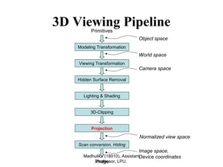
This document discusses different types of projections used in 3D viewing pipelines, including perspective and parallel projections. Perspective projections use a center of projection to project 3D points onto a 2D view plane, resulting in effects like foreshortening and vanishing points. Parallel projections project points parallel to a viewing direction, preserving scale and shape. Specific types of parallel projections discussed include orthographic, oblique, isometric, and axonometric projections.
A report on Morphological Image Processing presented by Sarjana Singh , a student of SOE, CUSAT (2007-2011 batch)
Morphology is a theory and technique for the analysis and processing of geometrical
structures, based on set theory and random functions. Morphology is most commonly
applied to digital images, but it can be employed as well on graphs, meshes, solids,
and many other spatial structures. Morphology was originally developed for binary
images, and was later extended to grayscale functions and images. The purpose of
morphological processing is primarily to remove imperfections added during segmentation.
The basic operations are erosion and dilation .Using the basic operations we can perform
opening and closing More advanced morphological operation can then be implemented
using combination of all of these.
A computer monitor is a 2D surface. A 3D scene rendered by OpenGL must be projected onto the computer screen as a 2D image. GL_PROJECTION matrix is used for this projection transformation.
Secrets of CryENGINE 3 Graphics TechnologyTiago Sousa
In this talk, the authors will describe an overview of a different method for deferred lighting approach used in CryENGINE 3, along with an in-depth description of the many techniques used. Original file and videos at http://crytek.com/cryengine/presentations
This is an introduction to 2D and 3 in computer graphics presented by daroko blog.
• Daroko blog (www.professionalbloggertricks.com)
• Presentation by Daroko blog, to see More tutorials more than this one here, Daroko blog has all tutorials related with IT course, simply visit the site by simply Entering the phrase Daroko blog (www.professionalbloggertricks.com) to search engines such as Google or yahoo!, learn some Blogging, affiliate marketing ,and ways of making Money with the computer graphic Applications(it is useless to learn all these tutorials when you can apply them as a student you know),also learn where you can apply all IT skills in a real Business Environment after learning Graphics another computer relate courses.ly
• Be practically real, not just academic reader
In parallel projection, coordinate positions are
transformed to the view plane along parallel lines.
In perspective projection, object position are
transformed to the view plane along lines that
converge to a point called projection reference point
(center of projection)
OPTICAL MICROSCOPY AND COORDINATE MEASURING MACHINE sangeetkhule
Introduction
Working principle
Classification
Construction and working
Different types of an optical scope
Process capabilities and analysis
Testing
Process parameters
Components and machine structure
Confocal laser scanning microscopy
Microscopic
Advantages
Applications
Advancement in CMM
Machine characteristics
Process parameters of CMM
Animation video
Research papers
Bar graphs and tables
Conclusion
References
NO1 Uk best vashikaran specialist in delhi vashikaran baba near me online vas...Amil Baba Dawood bangali
Contact with Dawood Bhai Just call on +92322-6382012 and we'll help you. We'll solve all your problems within 12 to 24 hours and with 101% guarantee and with astrology systematic. If you want to take any personal or professional advice then also you can call us on +92322-6382012 , ONLINE LOVE PROBLEM & Other all types of Daily Life Problem's.Then CALL or WHATSAPP us on +92322-6382012 and Get all these problems solutions here by Amil Baba DAWOOD BANGALI
#vashikaranspecialist #astrologer #palmistry #amliyaat #taweez #manpasandshadi #horoscope #spiritual #lovelife #lovespell #marriagespell#aamilbabainpakistan #amilbabainkarachi #powerfullblackmagicspell #kalajadumantarspecialist #realamilbaba #AmilbabainPakistan #astrologerincanada #astrologerindubai #lovespellsmaster #kalajaduspecialist #lovespellsthatwork #aamilbabainlahore#blackmagicformarriage #aamilbaba #kalajadu #kalailam #taweez #wazifaexpert #jadumantar #vashikaranspecialist #astrologer #palmistry #amliyaat #taweez #manpasandshadi #horoscope #spiritual #lovelife #lovespell #marriagespell#aamilbabainpakistan #amilbabainkarachi #powerfullblackmagicspell #kalajadumantarspecialist #realamilbaba #AmilbabainPakistan #astrologerincanada #astrologerindubai #lovespellsmaster #kalajaduspecialist #lovespellsthatwork #aamilbabainlahore #blackmagicforlove #blackmagicformarriage #aamilbaba #kalajadu #kalailam #taweez #wazifaexpert #jadumantar #vashikaranspecialist #astrologer #palmistry #amliyaat #taweez #manpasandshadi #horoscope #spiritual #lovelife #lovespell #marriagespell#aamilbabainpakistan #amilbabainkarachi #powerfullblackmagicspell #kalajadumantarspecialist #realamilbaba #AmilbabainPakistan #astrologerincanada #astrologerindubai #lovespellsmaster #kalajaduspecialist #lovespellsthatwork #aamilbabainlahore #Amilbabainuk #amilbabainspain #amilbabaindubai #Amilbabainnorway #amilbabainkrachi #amilbabainlahore #amilbabaingujranwalan #amilbabainislamabad
Hierarchical Digital Twin of a Naval Power SystemKerry Sado
A hierarchical digital twin of a Naval DC power system has been developed and experimentally verified. Similar to other state-of-the-art digital twins, this technology creates a digital replica of the physical system executed in real-time or faster, which can modify hardware controls. However, its advantage stems from distributing computational efforts by utilizing a hierarchical structure composed of lower-level digital twin blocks and a higher-level system digital twin. Each digital twin block is associated with a physical subsystem of the hardware and communicates with a singular system digital twin, which creates a system-level response. By extracting information from each level of the hierarchy, power system controls of the hardware were reconfigured autonomously. This hierarchical digital twin development offers several advantages over other digital twins, particularly in the field of naval power systems. The hierarchical structure allows for greater computational efficiency and scalability while the ability to autonomously reconfigure hardware controls offers increased flexibility and responsiveness. The hierarchical decomposition and models utilized were well aligned with the physical twin, as indicated by the maximum deviations between the developed digital twin hierarchy and the hardware.
Sachpazis:Terzaghi Bearing Capacity Estimation in simple terms with Calculati...Dr.Costas Sachpazis
Terzaghi's soil bearing capacity theory, developed by Karl Terzaghi, is a fundamental principle in geotechnical engineering used to determine the bearing capacity of shallow foundations. This theory provides a method to calculate the ultimate bearing capacity of soil, which is the maximum load per unit area that the soil can support without undergoing shear failure. The Calculation HTML Code included.
Explore the innovative world of trenchless pipe repair with our comprehensive guide, "The Benefits and Techniques of Trenchless Pipe Repair." This document delves into the modern methods of repairing underground pipes without the need for extensive excavation, highlighting the numerous advantages and the latest techniques used in the industry.
Learn about the cost savings, reduced environmental impact, and minimal disruption associated with trenchless technology. Discover detailed explanations of popular techniques such as pipe bursting, cured-in-place pipe (CIPP) lining, and directional drilling. Understand how these methods can be applied to various types of infrastructure, from residential plumbing to large-scale municipal systems.
Ideal for homeowners, contractors, engineers, and anyone interested in modern plumbing solutions, this guide provides valuable insights into why trenchless pipe repair is becoming the preferred choice for pipe rehabilitation. Stay informed about the latest advancements and best practices in the field.
Welcome to WIPAC Monthly the magazine brought to you by the LinkedIn Group Water Industry Process Automation & Control.
In this month's edition, along with this month's industry news to celebrate the 13 years since the group was created we have articles including
A case study of the used of Advanced Process Control at the Wastewater Treatment works at Lleida in Spain
A look back on an article on smart wastewater networks in order to see how the industry has measured up in the interim around the adoption of Digital Transformation in the Water Industry.
2. Madhulika (18010), Assistant
Professor, LPU.
Normalized view space
Modeling Transformation
Viewing Transformation
Lighting & Shading
3D-Clipping
Projection
Scan conversion, Hiding
Primitives
Image
Object space
World space
Camera space
Image space,
Device coordinates
Hidden Surface Removal
3D Viewing Pipeline
4. Viewing and Projection
• Camera Analogy:
1. Set up your tripod and point the camera at
the scene (viewing transformation).
2. Arrange the scene to be photographed into
the desired composition (modeling transformation).
3. Choose a camera lens or adjust the zoom
(projection transformation).
4. Determine how large you want the final
photograph to be - for example, you might
want it enlarged (viewport transformation).
Madhulika (18010), Assistant
Professor, LPU.
6. Madhulika (18010), Assistant
Professor, LPU.
Projections
• Our 3-D scenes are all specified in 3-D world coordinates
• To display these we need to generate a 2-D image - project
objects onto a picture plane
• So how do we figure out these projections?
Picture Plane
Objects in
World Space
7. Madhulika (18010), Assistant
Professor, LPU.
Projections
• Projection is just one part of the process of converting from
3-D world coordinates to a 2-D image
Clip against
view volume
Project onto
projection
plane
Transform to
2-D device
coordinates
3-D world
coordinate
output
primitives
2-D device
coordinates
10. Madhulika (18010), Assistant
Professor, LPU.
Projections
• There are two broad classes of projection:
– Parallel: Typically used for architectural and engineering
drawings
– Perspective: Realistic looking and used in computer graphics
Perspective Projection Parallel Projection
11. Classical viewing
Viewing requires three basic elements
• One or more objects
• A viewer with a projection surface
• Projectors that go from the object(s) to the projection surface
Classical views are based on the relationship among these
elements
• The viewer picks up the object and orients it how she would
like to see it
Each object is assumed to constructed from flat principal
faces
• Buildings, polyhedra, manufactured objects
Madhulika (18010), Assistant
Professor, LPU.
13. Madhulika (18010), Assistant
Professor, LPU.
Projections
ProjectionsProjections
PERSPECTIVE
Converging Projectors
(View Point)
PERSPECTIVE
Converging Projectors
(View Point)
PARALLEL
(View Direction)
PARALLEL
(View Direction)
OBLIQUE
Projector not ⊥ to
View plane
OBLIQUE
Projector not ⊥ to
View plane
ORTHOGRAPHIC
Projector ⊥ to
View plane
ORTHOGRAPHIC
Projector ⊥ to
View plane
GENERALGENERAL
MULTI VIEW
View plane || to
principal plane
MULTI VIEW
View plane || to
principal plane
AXONOMETRIC
View plane not ||
To principal plane
AXONOMETRIC
View plane not ||
To principal plane
1-Principal
vanishing point
1-Principal
vanishing point
2-Principal
vanishing point
2-Principal
vanishing point
3-Principal
vanishing point
3-Principal
vanishing point
Three viewsThree views
Auxiliary ViewAuxiliary View
Sectional ViewSectional View
ISOMETRIC
Equal angle with
all three axis
ISOMETRIC
Equal angle with
all three axis
DIMETRIC
Equal angle with
any two axis
DIMETRIC
Equal angle with
any two axis
TRIMETRIC
Unequal angle with
all three axis
TRIMETRIC
Unequal angle with
all three axis
CAVALIER
No foreshortening of lines
⊥ To XY-Plane
CAVALIER
No foreshortening of lines
⊥ To XY-Plane
CABINET
foreshortening of lines
⊥ To XY-Plane by 1/2
CABINET
foreshortening of lines
⊥ To XY-Plane by 1/2
15. Madhulika (18010), Assistant
Professor, LPU.
Perspective Projections
• Perspective projections are much more realistic than parallel
projections and are used by artists.
16. Madhulika (18010), Assistant
Professor, LPU.
Perspective Projections
• Perspective projections are described by
– Centre of projection: Eye of artists or lens of camera
– View Plane: Plane containing canvas or film strip or frame buffer
• A ray called projector is drawn from COP to object point, its
intersection with view plane determines the projected image
point on view plane.
X-axis
Projector
COP
View Plane
Y-axis
Z-axis
Object point
Projected point
19. Madhulika (18010), Assistant
Professor, LPU.
Perspective Projections
• There are a number of different kinds of perspective views
• The most common are one-point and two point perspectives
20. Madhulika (18010), Assistant
Professor, LPU.
Perspective Projections
• Perspective drawings are characterised by
1. Perspective foreshortening
2. Vanishing points
3. View Confusion
4. Topological Distortion
– These are also known as Perspective Anomalies.
– These anomalies enhance realism in terms of depth cues, but
distorts the actual size, shape and relationship between parts
of object.
21. Madhulika (18010), Assistant
Professor, LPU.
Perspective Projections
1. Perspective foreshortening: an illusion that objects and
lengths appear smaller as their distance form COP increases.
– We can see three balls have different dimensions, since
they placed at different distances they are projected to
same length
COP(0,0,-d)
Z-axis
Y-axis
22. Madhulika (18010), Assistant
Professor, LPU.
Perspective Projections
• Increasing the field of view angle increases the height of the
view plane and so increases foreshortening
23. Madhulika (18010), Assistant
Professor, LPU.
Perspective Projections
• The amount of foreshortening that is present can greatly affect
the appearance of our scenes
24. Madhulika (18010), Assistant
Professor, LPU.
Perspective Projections
2. Vanishing points: An illusion that certain sets of parallel
lines appear to meet at a point (called vanishing point).
– These are those lines that are not
parallel to view plane i.e. lines that
are not ⊥ to view plane normal.
– Principal vanishing points are
formed by apparent intersection of
lines parallel to one of the three
principal axes.
– The number of principal vanishing
points is determined by the number
of principal axis intersected by the
view plane.
X-axis
Z-axis
Y-axis COP
(0,0,-d)
L1
L2L’1
L’2
O
29. Three-point perspective
projection
Three-point perspective
projection
• Three-point perspective projection is used less
frequently as it adds little extra realism to that
offered by two-point perspective projection
• Three-point perspective projection is used less
frequently as it adds little extra realism to that
offered by two-point perspective projection
29
30. Madhulika (18010), Assistant
Professor, LPU.
Perspective Projections
3. View Confusion: An object behind the COP is projected
upside down and backward onto the view plane.
X-axis
Z-axis
Y-axis
COP(0,0,-d)
L1
L2
L’1
L’2
O
31. Madhulika (18010), Assistant
Professor, LPU.
Perspective Projections
4. Topological Distortion: All points lying on the plane
parallel to view plane and passing through the COP are
projected to ∞ by the perspective transformation.
– This may make a finite line segment
to appear as two infinite rays.
X-axis
Z-axis
Y-axis
COP(0,0,-d)
O
P1
P2
P’1
P’2
P3
∞ ∞
33. Madhulika (18010), Assistant
Professor, LPU.
Perspective Projections
• Although a perspective
projection is set up by
specifying the position and size
of the view plane and the
position of the projection
reference point called COP
• However, this can be kind of
awkward
34. Madhulika (18010), Assistant
Professor, LPU.
Perspective Projections
• The field of view angle can be a more intuitive way to specify
perspective projections
• This is analogous to choosing a lense for a camera
Field of view
35. Madhulika (18010), Assistant
Professor, LPU.
Perspective Projections
• We need one more thing to specify a perspective projections
using the filed of view angle
• The aspect ratio gives the ratio between the width sand height
of the view plane
37. Madhulika (18010), Assistant
Professor, LPU.
Parallel Projections
• Parallel projections are used by drafter and engineers to create working
drawings of an object as they preserve scale and shape
• These are described by
– Viewing Direction: which describe the direction of projection
– View Plane: Plane containing canvas or film strip or frame buffer
• A ray called projector is drawn || to Viewing direction and passing through
object point, its intersection with view plane determines the projected
image point on view plane.
X-axisView Plane
Y-axis
Z-axis
Object
Viewing Direction
Object’
38. Madhulika (18010), Assistant
Professor, LPU.
Parallel Projection
• Center of projection is at infinity
– Direction of projection (DOP) same for all points
DOP
View
Plane
39. Madhulika (18010), Assistant
Professor, LPU.
Parallel Projections
Parallel ProjectionsParallel Projections
OBLIQUE
Projector not ⊥ to
View plane
OBLIQUE
Projector not ⊥ to
View plane
ORTHOGRAPHIC
Projector ⊥ to
View plane
ORTHOGRAPHIC
Projector ⊥ to
View plane
GENERALGENERAL
MULTI VIEW
View plane || to
principal plane
MULTI VIEW
View plane || to
principal plane
AXONOMETRIC
View plane not ||
To principal plane
AXONOMETRIC
View plane not ||
To principal plane
Three viewsThree views
Auxiliary ViewAuxiliary View
Sectional ViewSectional View
ISOMETRIC
Equal angle with
all three axis
ISOMETRIC
Equal angle with
all three axis
DIMETRIC
Equal angle with
any two axis
DIMETRIC
Equal angle with
any two axis
TRIMETRIC
Unequal angle with
all three axis
TRIMETRIC
Unequal angle with
all three axis
CAVALIER
No foreshortening of lines
⊥ To XY-Plane
CAVALIER
No foreshortening of lines
⊥ To XY-Plane
CABINET
foreshortening of lines
⊥ To XY-Plane by 1/2
CABINET
foreshortening of lines
⊥ To XY-Plane by 1/2
41. Madhulika (18010), Assistant
Professor, LPU.
Oblique Projections
• DOP not perpendicular to view plane
Cavalier
(DOP θ = 45
o
)
Cabinet
(DOP θ = 63.4
o
)
45=φ
4.63=φ
42. • Cavalier Projection- It is obtained when the angle
between the oblique projectors and the plane of
projection is 45 degree and the foreshortening factors for
all three principal directions are equal.
• In Cavalier projection , the resulting figure is too thick.
Madhulika (18010), Assistant
Professor, LPU.
43. • Cabinet Projection- It is used to correct the deficiency
that is produced by Cavalier projection.
• An oblique projection for which the foreshortening factor
for the edge perpendicular to the plane of projection is
one-half is called Cabinet projection.
• For a cabinet projection, the angle between the
projectors and the plane of projection is 63.43.
Madhulika (18010), Assistant
Professor, LPU.
44. Madhulika (18010), Assistant
Professor, LPU.
Parallel Projections
• Identify type parallel projections
Orthographic Projection
Oblique Projection
Isometric Projection
45. Madhulika (18010), Assistant
Professor, LPU.
Parallel Projections
• Isometric projections have been used in computer games from
the very early days of the industry up to today
Q*Bert Sim City Virtual Magic Kingdom