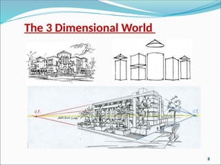
The 3 DimensionalWorld
Buildings are made up of simple
geometric shapes filled with
empty space. For example, when
you breakdown this building it is
just a collection of boxes,
cylinders, pyramids and cones.
3
4.
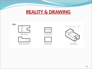
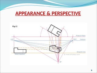
REALITY
The actualappearance of
the object (according to its
actual dimensions) is known
as the Reality.
In other words , there are
true relationships between
various lines of plans,
elevations etc.
4
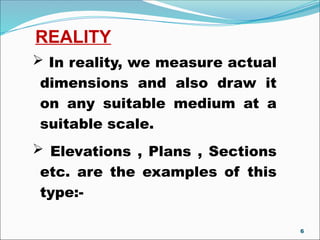
REALITY
In reality,we measure actual
dimensions and also draw it
on any suitable medium at a
suitable scale.
Elevations , Plans , Sections
etc. are the examples of this
type:-
6
7.
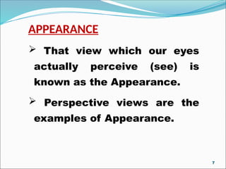
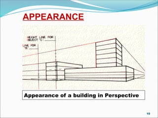
APPEARANCE
That viewwhich our eyes
actually perceive (see) is
known as the Appearance.
Perspective views are the
examples of Appearance.
7
INTRODUCTION
An Architectcan offer some
amazing images of one’s dream
house in architectural language.
In other words an Architect
shows his prepared drawings in
the 3-d views to impress his
clients.
11
12.
INTRODUCTION
Perspective drawings areused to
provide a pictorial representation of
an object, as they produce an image
of an object in three dimensions that
is very similar to what the human eye
sees.
It is used to provide a client an image
that gives a good representation of
how the project will look when it is
built.
12
13.
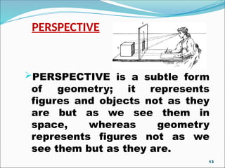
PERSPECTIVE
PERSPECTIVE is asubtle form
of geometry; it represents
figures and objects not as they
are but as we see them in
space, whereas geometry
represents figures not as we
see them but as they are.
13
14.
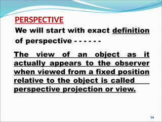
We will startwith exact definition
of perspective - - - - - -
The view of an object as it
actually appears to the observer
when viewed from a fixed position
relative to the object is called
perspective projection or view.
PERSPECTIVE
14
INTRODUCTION
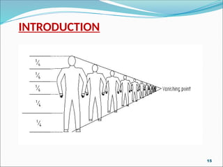
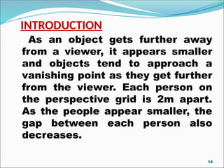
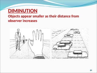
As an objectgets further away
from a viewer, it appears smaller
and objects tend to approach a
vanishing point as they get further
from the viewer. Each person on
the perspective grid is 2m apart.
As the people appear smaller, the
gap between each person also
decreases.
16
17.
#. In perspectiveprojection, the
eye is assumed to be situated at
a definite position relative to the
object .
#. The picture plane (vertical
plane) is placed in between the
object and the eye.
INTRODUCTION
17
18.
#. Visual raysfrom the eye to
the object pierce the picture
plane and form an image on it.
#. This image is known as
perspective of the object.
INTRODUCTION
18
19.
As we seedifferent views of an
object when viewed from different
angles , same way perspective
drawings will depend on
RELATIVE POSITION OF
• PICTURE PLANE
• POINT OF SIGHT
• OBJECT
INTRODUCTION
19
20.
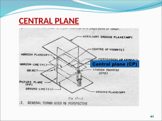
TERMINOLOGY OF PERSPECTIVE
#.Before going further it would be better if
we understand general terms used in
perspective
#. Some of these are as follows---------
20
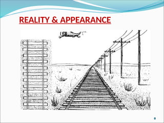
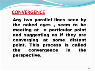
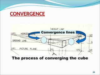
CONVERGENCE
Any two parallellines seen by
the naked eyes , seem to be
meeting at a particular point
and suggesting as if they are
converging at some distant
point. This process is called
the convergence in the
perspective.
22
23.
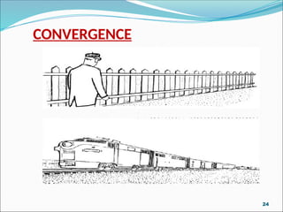
CONVERGENCE
Convergence playsan
important roles in the field
of perspective.
All the perspective views
are the results of the
convergence.
For example :-----
23
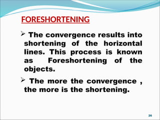
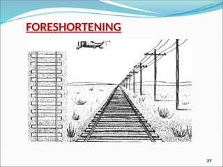
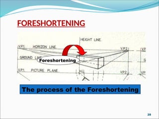
FORESHORTENING
The convergenceresults into
shortening of the horizontal
lines. This process is known
as Foreshortening of the
objects.
The more the convergence ,
the more is the shortening.
26
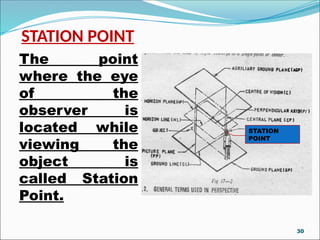
STATION POINT
The point
wherethe eye
of the
observer is
located while
viewing the
object is
called Station
Point.
DRG-4
STATION
POINT
30
31.
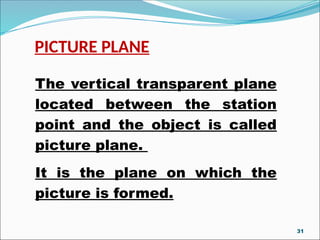
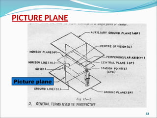
PICTURE PLANE
The verticaltransparent plane
located between the station
point and the object is called
picture plane.
It is the plane on which the
picture is formed.
31
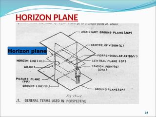
HORIZON PLANE
An imaginaryhorizontal plane
at the level of station point that
is observer’s eye , is called
horizontal plane .
This plane is above the ground
plane and perpendicular to the
picture plane.
33
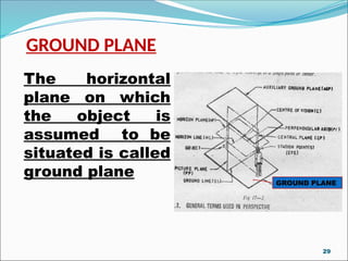
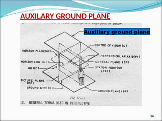
AUXILIARY GROUND PLANE
Ahorizontal plane which is
placed parallel and above the
horizon plane is called auxiliary
ground plane.
The top view of the object is
projected on this plane.
35
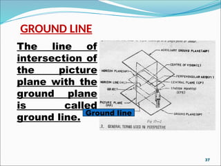
GROUND LINE
The lineof
intersection of
the picture
plane with the
ground plane
is called
ground line.
DRG-4
Ground line
37
38.
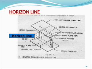
HORIZON LINE
Thehorizon is the line at
which the sky and earth appear
to meet . It is located at the
eyelevel of the viewer.
The line of intersection of the
horizon plane with the picture
plane is called horizon line.
It is parallel to the ground line.
38
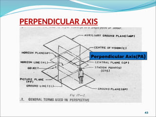
PERPENDICULAR AXIS
A linewhich is drawn through
the station point and
perpendicular to the picture
plane is called perpendicular
axis.
It is also called line of vision or
line of sight.
42
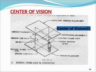
CENTER OF VISION
Thepoint through which
the perpendicular axis
pierces the picture plane
and lies on the horizon line
is called the centre of
vision.
44
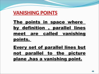
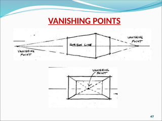
VANISHING POINTS
The pointsin space where
by definition , parallel lines
meet are called vanishing
points.
Every set of parallel lines but
not parallel to the picture
plane ,has a vanishing point.
46
VANISHING POINTS
The typeof the perspectives
are also dependant upon the
number of these points.
For example:-
48
49.
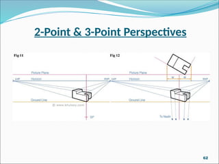
VANISHING POINTS
Onepoint perspective has one
vanishing point.
Two point perspective has two
vanishing points.
Three point perspective has
three vanishing points.
49
50.
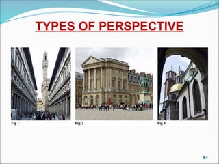
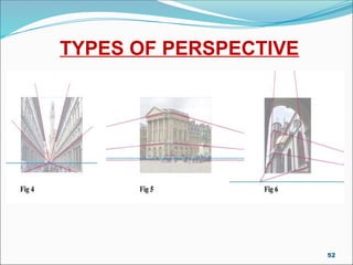
TYPES OF PERSPECTIVE
Mainlyperspectives are of
three types ,according to the
number of vanishing points
required to make them------------
ONE POINT OR PARALLEL
TWO POINT OR ANGULAR
THREE POINT OR OBLIQUE
50
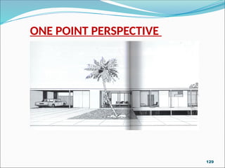
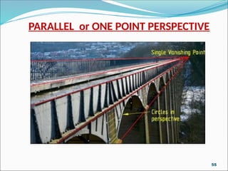
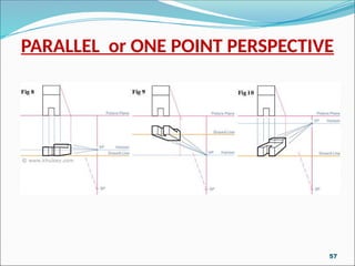
PARALLEL OR ONEPOINT
PERSPECTIVE
When one face of the object is
parallel to the picture plane and
the other perpendicular to it ,the
resulting picture is called
parallel or one point perspective.
53
54.
PARALLEL or ONEPOINT PERSPECTIVE
It is used when one face of the
object viewed is perpendicular to
the line of sight from the viewer.
The one point perspective is used
for representation of streetscape,
interiors of buildings and machine
parts.
54
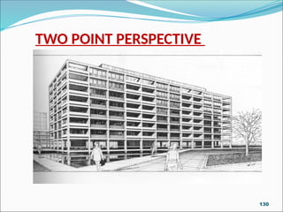
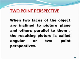
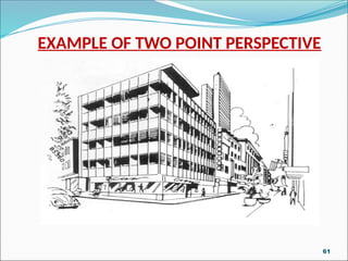
TWO POINT PERSPECTIVE
Whentwo faces of the object
are inclined to picture plane
and others parallel to them ,
the resulting picture is called
angular or two point
perspectives.
58
59.
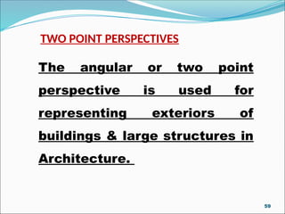
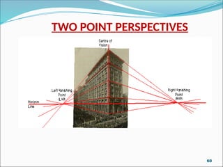
TWO POINT PERSPECTIVES
Theangular or two point
perspective is used for
representing exteriors of
buildings & large structures in
Architecture.
59
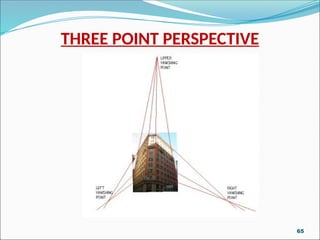
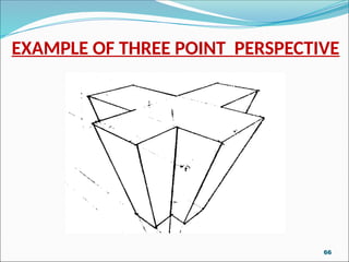
THREE POINT PERSPECTIVE
Whenall faces of the object
are oblique to the picture
plane , the resulting picture
is called oblique or three
point perspectives.
63
64.
THREE POINT PERSPECTIVE
Thisis mainly used for
objects in space and for
skyscrapers etc.
And in this case we have
object which is inclined to
ground plane.
64
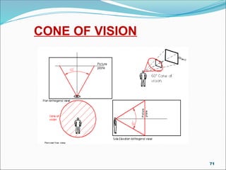
CONE OF VISION
The cone of vision is required
to obtain the limits of the
drawing.
The field of vision is known to
be more than 180 degrees .
But it is not possible to see
clearly over this whole range.
68
69.
CONE OF VISION
The normal maximum
range within which it is
possible to see clearly and
easily is accepted as being
less than 90 degrees .
And is seldom taken as
more than 60 degrees.
69
70.
CONE OF VISION
But for the purpose of
perspective drawing it is
usually limited to 60 degrees
or less.
Any thing outside this cone
of vision will give us a
distorted view.
70
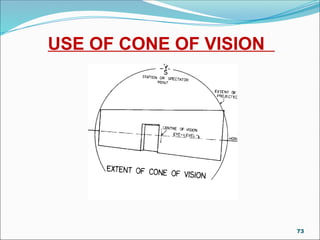
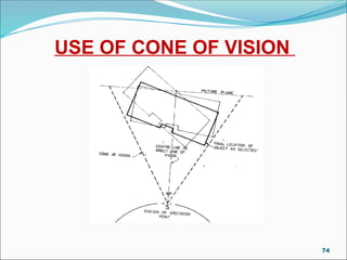
CONE OF VISION
Toobtain a wider coverage
with the cone of vision:
It is necessary to move
backwards from the object.
it is not enough simple to
widen the cone of vision.
72
CONE OF VISION
When deciding on the position
from which to view the
building or object.
It is necessary to fit the
whole- or the part which it is
intended to include in the
drawing-inside Cone of Vision.
75
76.
CONE OF VISION
Cone of Vision governs the
distance from which one
should view the object.
The apex of the cone of
vision is known as the Station
Point, the Spectator Point or
the Viewing Point.
76
77.
CONE OF VISION
The centre line of this cone
is known as the Centre Line
of Vision or the Direct Line of
Vision.
This line is represented in
plan by a vertical line and in
elevation by as horizontal
line.
77
78.
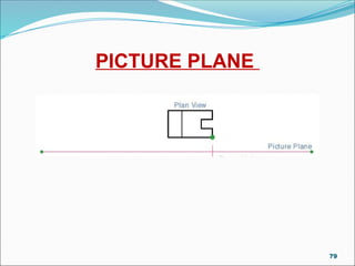
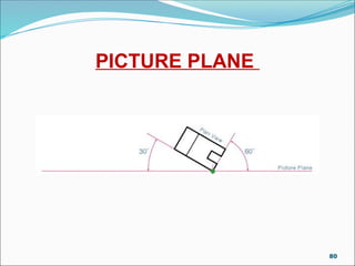
PICTURE PLANE
ThePicture Plane [PP] is an
imaginary plane on which the
perspective is supposed to be
drawn.
This plane is shown as a line
in plan and is always at right
angles to the Direct Line of
Vision.
78
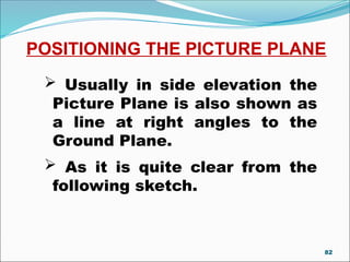
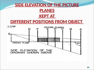
POSITIONING THE PICTUREPLANE
Usually in side elevation the
Picture Plane is also shown as
a line at right angles to the
Ground Plane.
As it is quite clear from the
following sketch.
82
83.
SIDE ELEVATION OFTHE PICTURE
PLANES
KEPT AT
DIFFERENT POSITIONS FROM OBJECT
DRG-13
83
84.
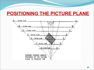
POSITIONING THE PICTUREPLANE
As shown in the previous
diagrams it is quite clear that
the size of the object is very
much dependant on the
position of Picture Plane.
84
POSITIONING THE PICTUREPLANE
And it is also quite clear
from the figure that closer
the observer to the picture
plane , smaller the resulting
perspective.
86
87.
POSITIONING THE PICTUREPLANE
The thing we must observe
here is that:
It is the size only that is
varying according to the
position of Picture Plane,
otherwise there is no change
in shape/form or the view is
always the same.
87
88.
HEIGHT LINE
Theheight line is the line in
the perspective projection
used for taking all vertical
heights , which are measured
using the same scale as that
of plan.
88
89.
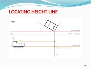
LOCATING HEIGHT LINE
The location of this line is
found by projecting a line as
the continuation of one of the
longer sides of plan of the
object backward or forward to
meet the picture plane; to
mark its position as a point for
Height Line on Picture Plane.
89
LOCATING HEIGHT LINE
From this point where the
said two lines intersect each
other, a vertical line is drawn
to cross the Eye Level or
Horizon Line & right up to the
Ground Line.
91
92.
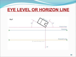
EYE LEVEL ORHORIZON LINE
The Eye Level , which
coincides with the Horizon
Line in the perspective
projection , is a horizontal
line drawn at a convenient
point above or below the plan
of the Picture Plane.
92
EYE LEVEL ORHORIZON LINE
The location of this line is
entirely at the discretion of the
person.
And the main consideration is
the space and the equipment
available to him.
95
96.
EYE LEVEL ORHORIZON LINE
As all lines projected on plan
have to be projected vertically
to this line .
It is wise to select a position
in which this can be done with
the least effort.
96
97.
EYE LEVEL ORHORIZON LINE
This line represents the height
of the observing eye and all
heights are measured in relation
to this line.
97
98.
GROUND LINE
Theground line in
perspective projection is the
line of the ground in relation
to the eye level.
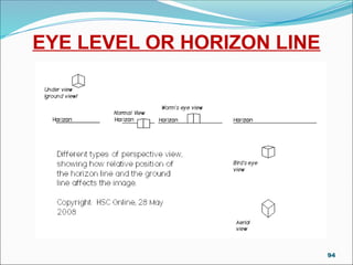
Under normal circumstances
this is considered to be 5 ft.
below the eye level or the
horizon line.
98
99.
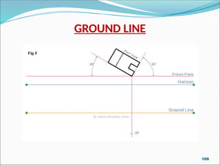
GROUND LINE
TheGround Line is located in
perspective projection by
measuring down the height
line from the Horizon Line as
scale distance of 5 ft.
All height measurements of
the object should be measured
from the ground line up.
99
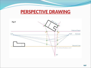
VANISHING POINTS
#. VanishingPoints are points
located on the Picture Plane and
the Horizon Line to which the
lines of the perspective
projection will converge.
101
102.
VANISHING POINTS
#. Alllines on plan in one
direction will converge in the
perspective to the vanishing
points in the same direction.
#. The number of vanishing
points in a perspective may
vary .
102
103.
VANISHING POINTS
#. Numberof vanishing points
start from one and two in case
of two point perspective or
more depending on the
complicated objects.
103
104.
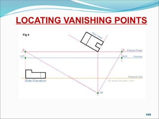
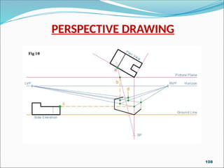
LOCATING VANISHING POINTS
#.The Vanishing Points are
found by drawing lines from the
Station Point parallel to the
sides of the object to meet the
Picture Plane in plan.
104
Elements of Perspective
Definitionof Terms and some rules of thumb
Perspective: the method of drawing so that
objects represented have apparent depth
and distance…
The Merriam-Webster Dictionary
Picture Plane: the imaginary window that
frames the things you are attempting to
draw or paint
111
112.
Elements of Perspective
Definitionof Terms and some rules of thumb
Horizon Line – were the sky meets the earth
Eye Level - the horizontal level in line with
your eyes when you’re looking straight
ahead
Vanishing Point – the point at which all
parallel lines meet and or vanish as they
recede into the distance
112
113.
Elements of Perspective
Definitionof Terms and some rules of thumb
Converging Lines – parallel lines that
appear to approach the same point on the
horizon
Overlap – the placement of one object in
front of another to create the illusion of
depth
113
114.
Elements of Perspective
Definitionof Terms and some rules of thumb
Size and Space Variation – the drawing
of objects that are in reality equally
sized and spaced objects so that they
get smaller and closer together as they
approach the horizon
114
115.
Elements of Perspective
Definitionof Terms and some rules of thumb
Modeling – the shading and texturing of an
object in a drawing so that it appears to have
form, depth, a front, sides and a back, there is
something behind it if you could only see.
Color and Value Change – the use of a lighter
value of color in the areas you want to appear
further in the distance
115
116.
Things appear togrow smaller as they
recede into the distance
All horizontal parallel lines that are
above the Eye Level line appear to go
downward as they recede into the
distance
Elements of Perspective
Rules of Thumb
116
117.
Elements of Perspective
Rulesof Thumb
All horizontal parallel lines that are below the
Eye Level line appear to go upward as they
recede into the distance
Vertical lines in 1 point and 2 point
perspective will always be parallel to the
sides of your picture plane
Horizontal lines will only be parallel to the top
and bottom of the page in 1 point perspective
117
118.
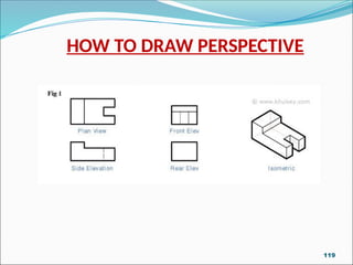
HOW TO DRAWPERSPECTIVE
For making perspective of any
object or building we should
have the following set of
drawings, drawn to some same
convenient scale:
PLANS
ELEVATIONS
SECTIONS
118
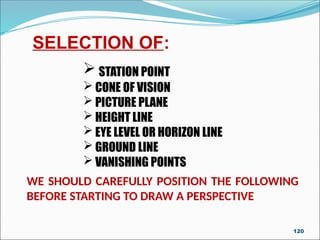
WE SHOULD CAREFULLYPOSITION THE FOLLOWING
BEFORE STARTING TO DRAW A PERSPECTIVE
SELECTION OF:
STATION POINT
CONE OF VISION
PICTURE PLANE
HEIGHT LINE
EYE LEVEL OR HORIZON LINE
GROUND LINE
VANISHING POINTS
120
121.
The position ofstation point is
very important in making an
attractive perspective.
There fore , it should be located
at the point so as to view the
object in the best possible
manner.
SELECTION OF STATION POINT
121
122.
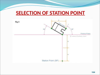
SELECTION OF STATIONPOINT
There is no fixed rule as our
position of best station point
changes with the:
SIZE OF OBJECT
RELATIONSHIP BETWEEN VARIOUS
PARTS OF OBJECT
122
123.
DEPENDANCE ON SIZEOF THE OBJECT
#. For large objects the station
point is usually taken at a
normal standing heights of a
person that is about 1.8 meters.
123
DEPENDANCE ON SIZEOF THE OBJECT
#. For small objects, the station
point should be fixed at such a
height so as to give a good view
of the top surface as well as side
surfaces.
125
126.
RELATIONSHIP BETWEEN VARIOUSPARTS
OF OBJECT
#. For objects having heights
and widths more or less equal,
the station point may be fixed in
such a way that the angle
between the visual rays from the
station point to the outermost
boundaries of the object make
approximately 30 degree angle.
126
127.
# Cone ofvision should be
between 30-35 degrees all
round the Centre Line of Vision.
# The distance of the station
point from the picture plane
should be equal to twice the
greatest dimension of the
object.
WE MUST ENSURE
127
128.
WE MUST ENSURE
#.The station point should be
so situated in front of the
object that the center of vision
be somewhat near the picture’s
centre.
128
![PERSPECTIVE DRAWING
A Power Point Presentation
By: Yash Pathania Sr. Lecturer [Arch.] GPCG, Amritsar](https://image.slidesharecdn.com/introterminologycolor-250418053207-ac7f79ec/85/Perspective-Drawing-INTRO-TERMINOLOGY-COLOR-pptx-1-320.jpg)
![PERSPECTIVE DRAWING
A Power Point Presentation
By: Yash Pathania Sr. Lecturer [Arch.] GPCG, Amritsar](https://image.slidesharecdn.com/introterminologycolor-250418053207-ac7f79ec/75/Perspective-Drawing-INTRO-TERMINOLOGY-COLOR-pptx-1-2048.jpg)
![PICTURE PLANE
The Picture Plane [PP] is an
imaginary plane on which the
perspective is supposed to be
drawn.
This plane is shown as a line
in plan and is always at right
angles to the Direct Line of
Vision.
78](https://image.slidesharecdn.com/introterminologycolor-250418053207-ac7f79ec/85/Perspective-Drawing-INTRO-TERMINOLOGY-COLOR-pptx-78-320.jpg)