


![Addressing Modes
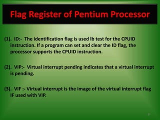
• 80386 supports total 11 addressing modes.
• Scaled Indexed Mode: Contents of the an index register are multiplied by a
scale factor (the valid scale factors are 1,2,4 & 8) that may be added further to
get the operand offset.
e.g. MOV EBX, LIST [ESI*2]
• Based Scaled Indexed Mode: Contents of the an index register are multiplied by
a scale factor and then added to base register to obtain the offset.
e.g. MOV EBX, LIST [EDX*4] [ECX]
• Based Scaled Indexed Mode with Displacement: The Contents of the an index
register are multiplied by a scaling factor and the result is added to a base
register and a displacement to get the offset of an operand.
e.g. MOV EAX, LIST [ESI*2] [EBX+0800]
14](https://image.slidesharecdn.com/80386ppt-120415221348-phpapp01/85/Pentium-80586-Microprocessor-By-Er-Swapnil-Kaware-14-320.jpg)


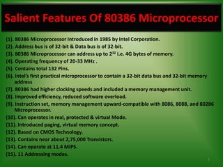
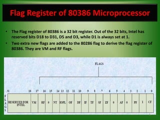
The 80386 microprocessor was introduced by Intel in 1985. It had a 32-bit data bus and 32-bit address bus, allowing it to access up to 4GB of memory. It improved on the 80286 by including a memory management unit and paging capabilities. The 80386 operated in real, protected, and virtual modes and could address memory using various addressing modes including scaled indexed addressing. It had enhanced 32-bit registers and introduced debugging features like breakpoints using debug registers. Paging divided memory into fixed-size pages allowing more efficient memory management for multitasking systems.


![[ASM] Lab2](https://cdn.slidesharecdn.com/ss_thumbnails/asmlab2-161012104901-thumbnail.jpg?width=640&height=640&fit=bounds)


