BEE 3
Node, loop,mesh and branch
Node: A node is simply a point of
connection of two or more circuit
elements. You are cautioned to note that,
although one node can be spread out with perfect
conductors, it is still only one node. This is illustrated
in Fig. b, where the circuit has been redrawn. Node 5
consists of the entire bottom connector of the
circuit. Nodes are mentioned by numbers 1, 2, 3, 4
and 5.
Loop: A loop is simply any closed path through
the circuit in which no node is encountered
more than once. For example, starting from node
1, one loop would contain the elements R1, v2, R4
and i1; another loop would contain R2, v1, v2, R4
and i1; and so on. However, the path R1, v1, R5, v2,
R3 and i1 is not a loop because we have encountered
node 3 twice.
Mesh: A mesh is a loop that has no other
loops inside of it. In figure b, starting from node
2, one mesh is R3, v2 and R4 and starting from node
1, the other mesh is R1, v1 and R2 and so on.
Branch: Finally, a branch is a portion of a
circuit containing only a single element and
the nodes at each end of the element. The
circuit in the figure contains eight branches.
4.
BEE 4
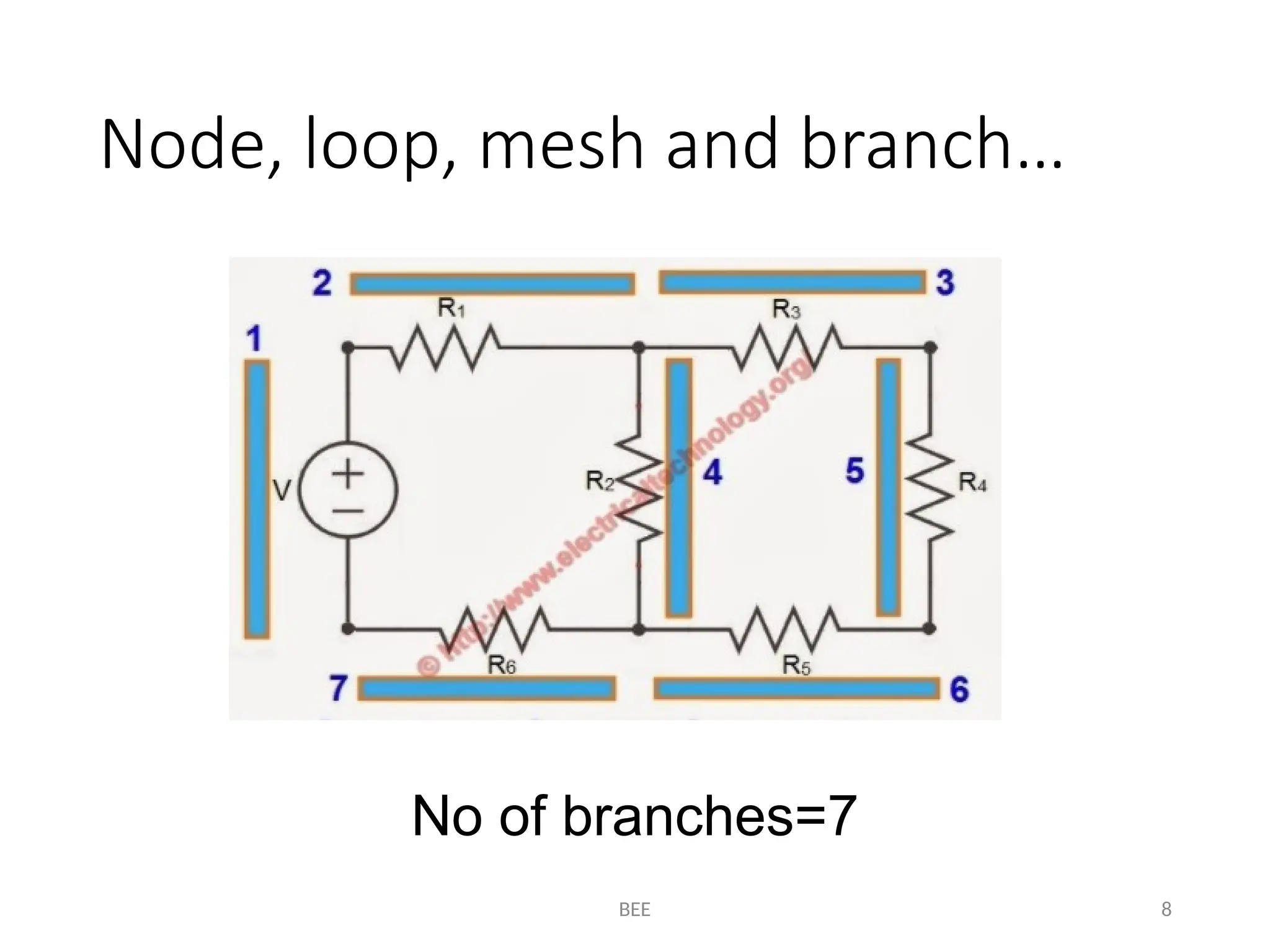
Node, loop,mesh and branch…
Question: Count the number of nodes, loops, meshes
and branches in the circuit given below.
BEE 9
Kirchhoff’s CurrentLaw (KCL)
Before discussing the first law
known as KCL, it is assumed that
current entering a node will be
taken as positive while current
leaving a node will be taken as
negative
Considering node 2, i1 and i6 are
leaving the node so are negative
while i4 is entering a node so it is
positive
Considering node 1, i1 is entering
the node so it is positive while i2
and i3 are leaving the node so
they are negative
10.
BEE 10
Kirchhoff’s CurrentLaw (KCL)
Statement: The algebraic
sum of all the currents
entering any node is zero
Mathematically
Currents entering a node
are I1 and I2 and therefore
are positive
Currents leaving a node
are I3, I4 and I5 and
therefore are negative
11.
BEE 11
Kirchhoff’s CurrentLaw (KCL)
According to KCL, the algebraic sum
of all currents entering a node is
equal to zero, mathematically
Multiplying the above equation by “-1”
Which simply states the algebraic sum of all
the currents leaving a node is zero. This is
alternative form of KCL.
12.
BEE 12
Kirchhoff’s CurrentLaw
Taking all the negative terms of eq. (i) to the right side fo the equation
From the above equation we can state KCL as follows:
“The sum of all the currents (magnitude) entering a node is equal to the sum of all the
currents (magnitude) leaving a node”
The above statement is another alternative form of KCL
13.
BEE 13
Numerical Exampleon KCL
Question: Write KCL
equation for every
node of the circuit
shown below
Solution:
According to KCL,
For node 1, KCL eq. is
For node 2, KCL eq. is
For node 3, KCL eq. is
For node 4, KCL eq. is
For node 5, KCL eq. is
14.
BEE 14
Numerical Exampleon KCL…
Solution:
Labelling the currents
and nodes and then
applying KCL at each
node
Question: Find the
currents I1 and I2 in the
circuit shown below:
BEE
Kirchhoff’s Voltage Law(KVL)
Before discussing the second law known as KVL, it is
assumed that an increase in the charge’s energy will
be considered as negative as the current first
encounter negative sign and is known as the
potential rise while a decrease in the charge’s energy
will be considered as positive as the current first
encounter a positive sign and this decrease of
charge’s energy is termed as potential drop
Finally, we employ the convention to indicate the
voltage of point “a” with respect to point “b”: that is,
the variable for the voltage between point “a” and
point “b”, with point “a” considered positive relative
to point “b”.
Before applying KVL, we assume either clockwise
current or anticlockwise current in a loop according
to our wish
If we consider clockwise current I as shown in Figure
B on right hand side, then the polarities will be
At V1=potential rise=considered negative
At V2=potential drop=considered positive
At V3=potential rise=considered negative
16
Figure A
Figure B
17.
BEE
Kirchhoff’s Voltage Law(KVL)
Statement: The algebraic sum of
all the voltages around any closed
loop is zero
Mathematically
Assuming clockwise current in figure A and
then applying KVL as shown in figure B
Taking all the negative terms of eq. 1 on right
hand side
The sum of all the voltage (magnitude)
drops is equal to the sum of all the voltage
(magnitude) rises in a closed loop. This is
alternative form of KVL.
17
Figure A
Figure B
18.
BEE
Kirchhoff’s Voltage Law(KVL)
Question: Find V3
in the circuit given
below:
18
Solution:
First we assume a
clockwise direction of the
current in the loop and
label all the voltages and
then indicate all the
voltage drops and voltage
rises as shown in the
circuit given in the next
slide
BEE
Kirchhoff’s Voltage Law(KVL)
Question: Find Vae and Vec in the circuit
given below:
Solution: Vae means that “point a” is
positive with respect to “point e” while Vec
means that “point e” is positive with respect
to “point c”. Assuming anticlockwise
direction of currents in both hypothetical
loops “aef” and “ecd” respectively
20
Applying KVL to the loop “aef”
Applying KVL to loop “ecd”
Dffsdfsdfsfsfddsfsdf
sfdfsfsdfsf
21.
BEE 21
Homework
Question: WriteKCL
equation for every
node of the circuit
shown below. Also
find the unknown
currents if
Question: Find in the circuit
shown below: