Pre-engineered buildings are factory-built structures consisting of prefabricated components that are assembled on-site. The components are designed and manufactured based on a client's requirements and structural calculations. This allows the building to be lighter and less expensive than traditional on-site construction, with components delivered and assembled more quickly.
In this document
Powered by AI
Introduction to Pre-Engineered Buildings and their components, emphasizing client-specific designs, factory fabrication, and on-site assembly.
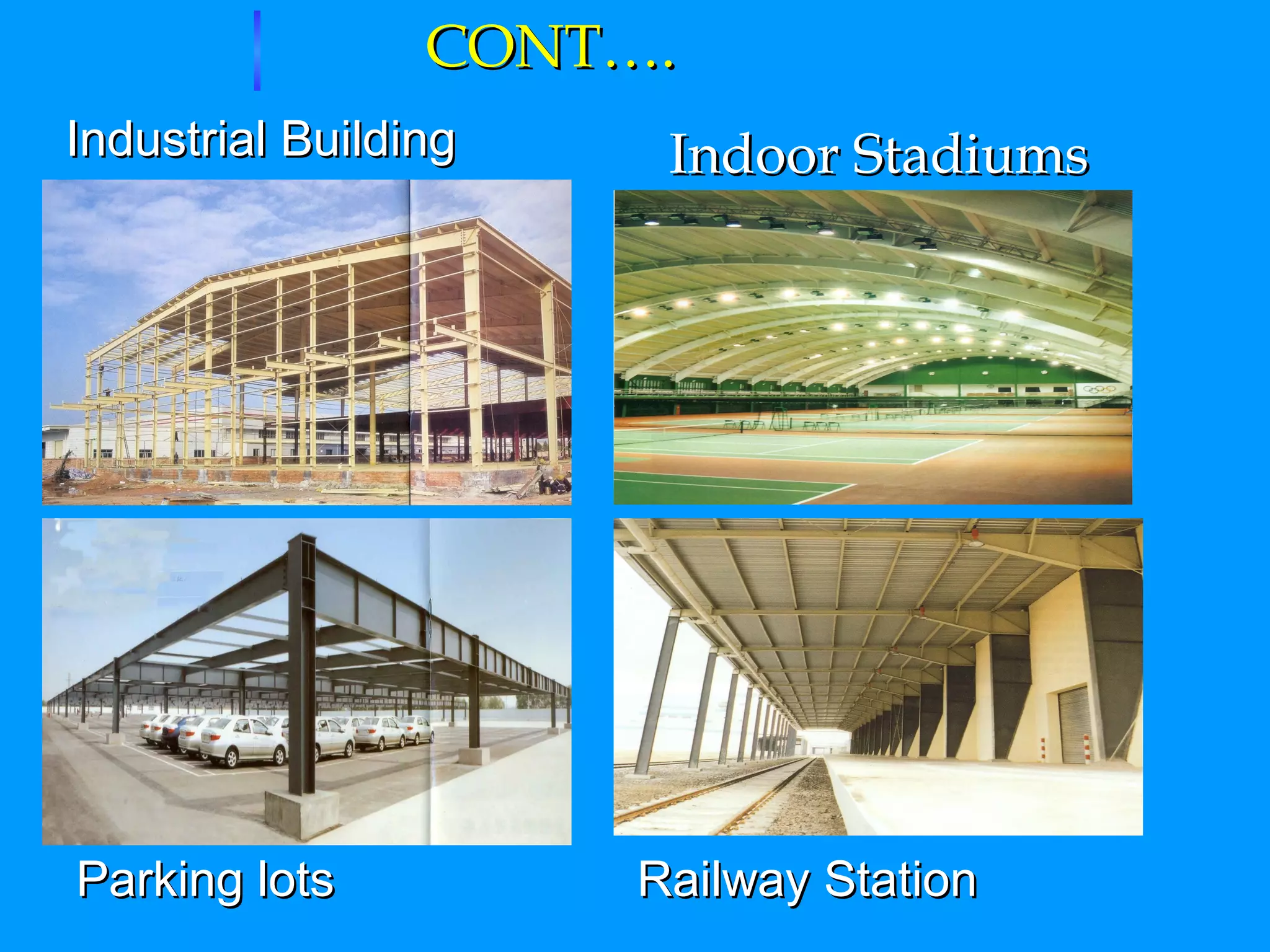
The origins of Pre-Engineered Buildings (PEB) in the USA due to the high cost of steel, leading to applications in various structures like industrial buildings and sports facilities.
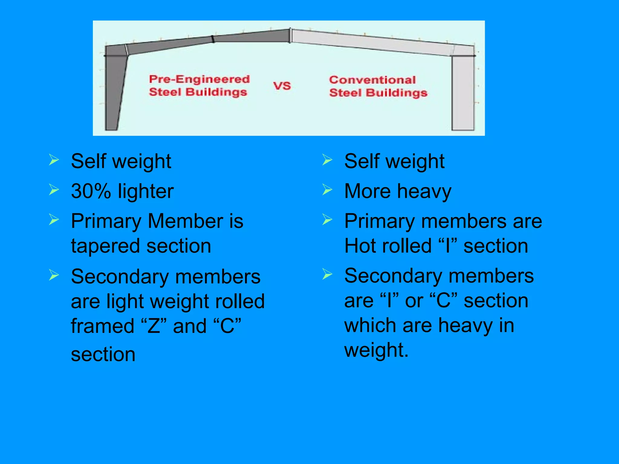
Comparison of self-weight in building frames, highlighting tapered sections as lighter alternatives versus heavier hot rolled sections.
The advantages of PEB in delivery times (6-8 weeks) and erection cost versus traditional methods which take longer (20-26 weeks) and are costlier.
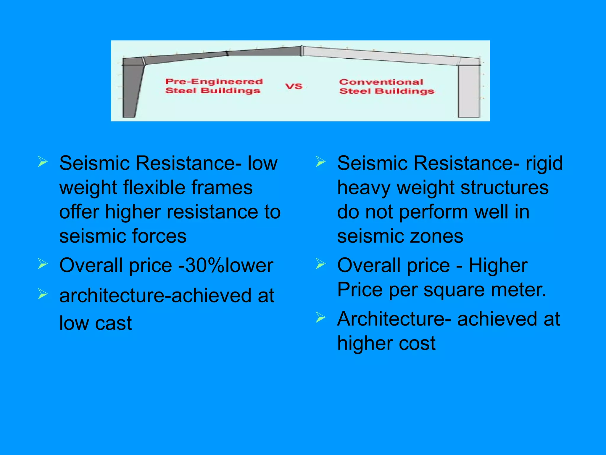
Comparison of seismic performance; PEB provides 30% lower cost and better resistance compared to traditional heavy structures that are more expensive.
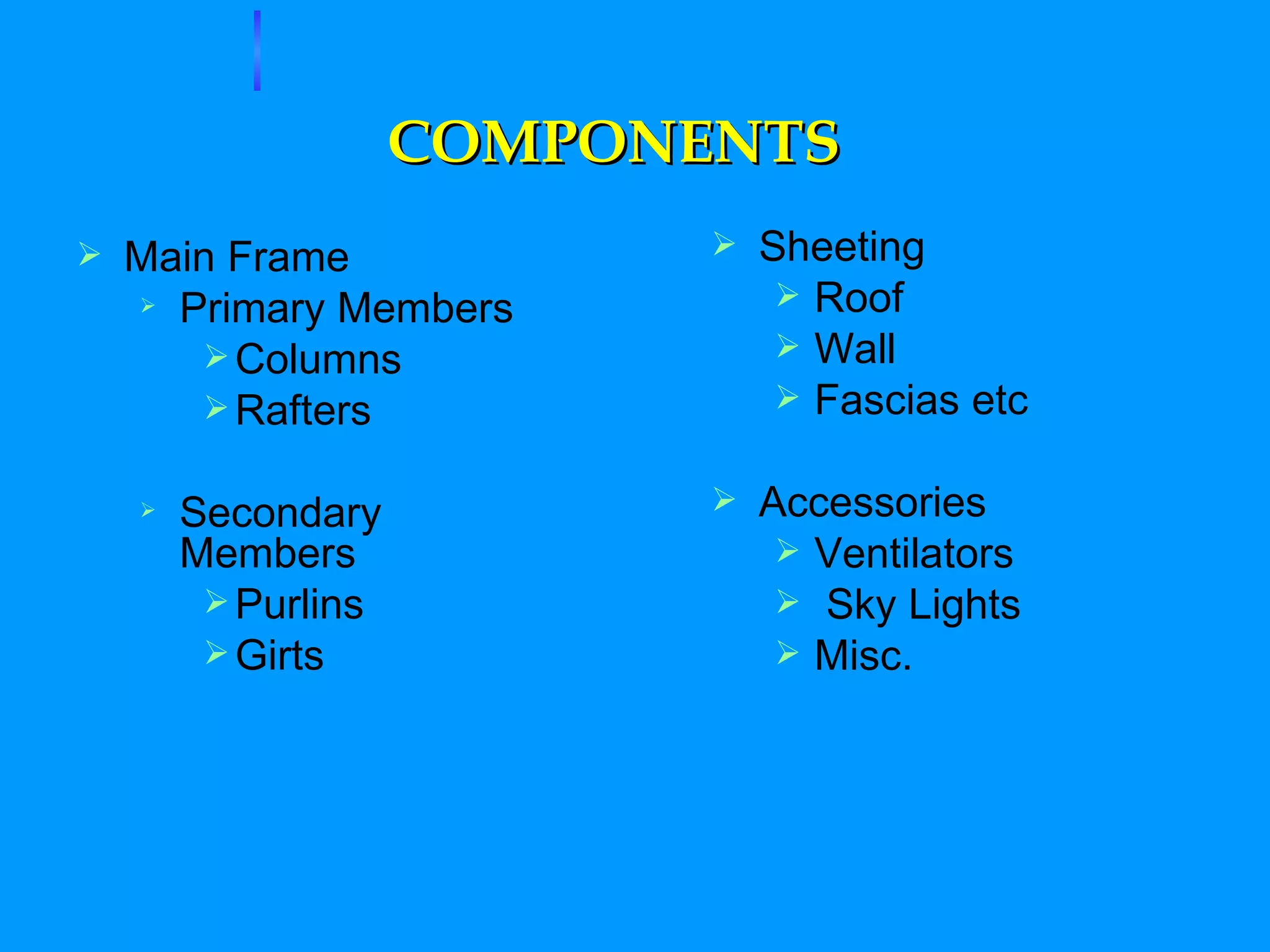
Key elements of PEB systems including primary and secondary members, along with notable accessories like crane brackets and mezzanine floors.
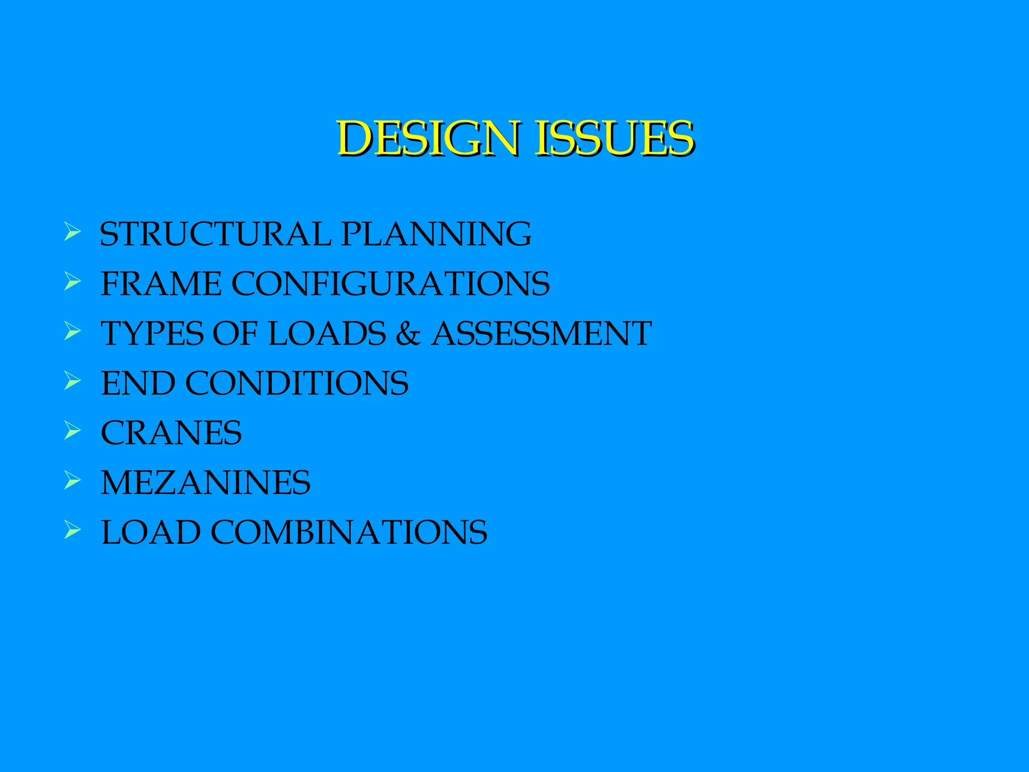
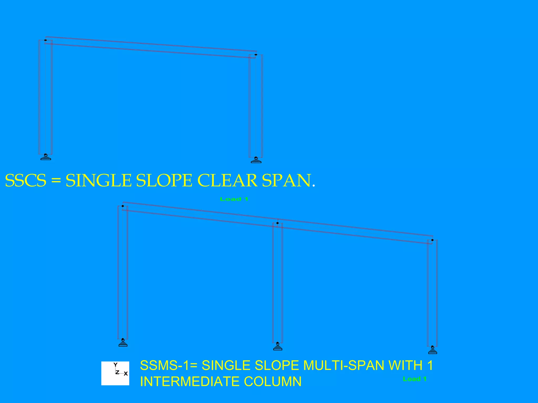
Important structural considerations such as frame configurations, load assessments, and standards for design based on American codes and IS codes.
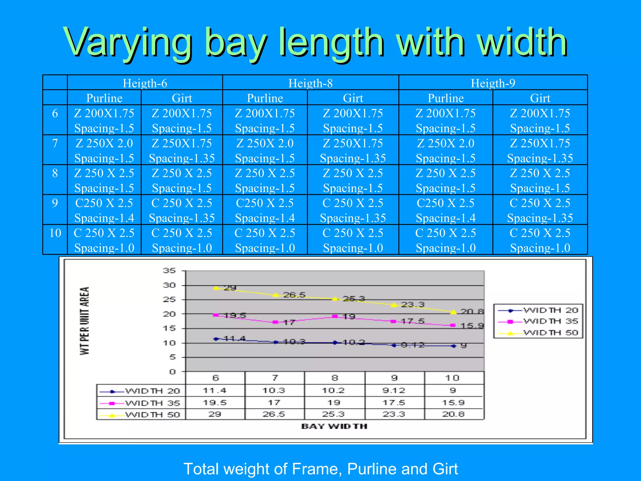
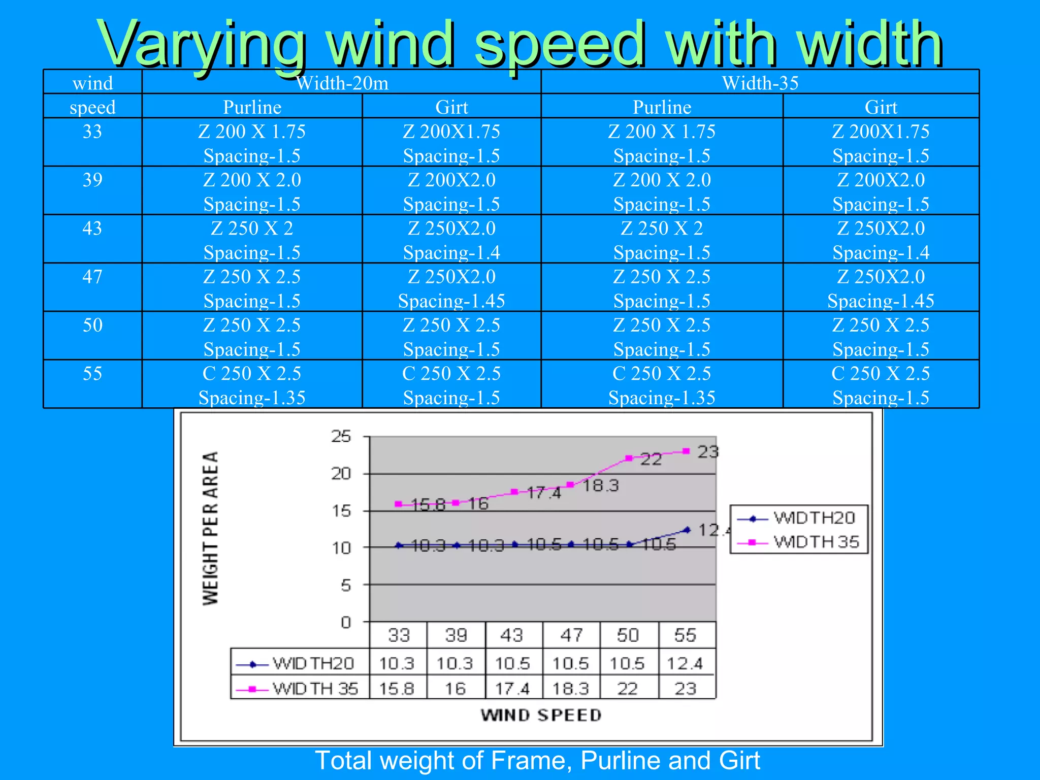
Optimization of frame components involving width, height, spacing, and structural integrity focused on various design parameters for efficiency.
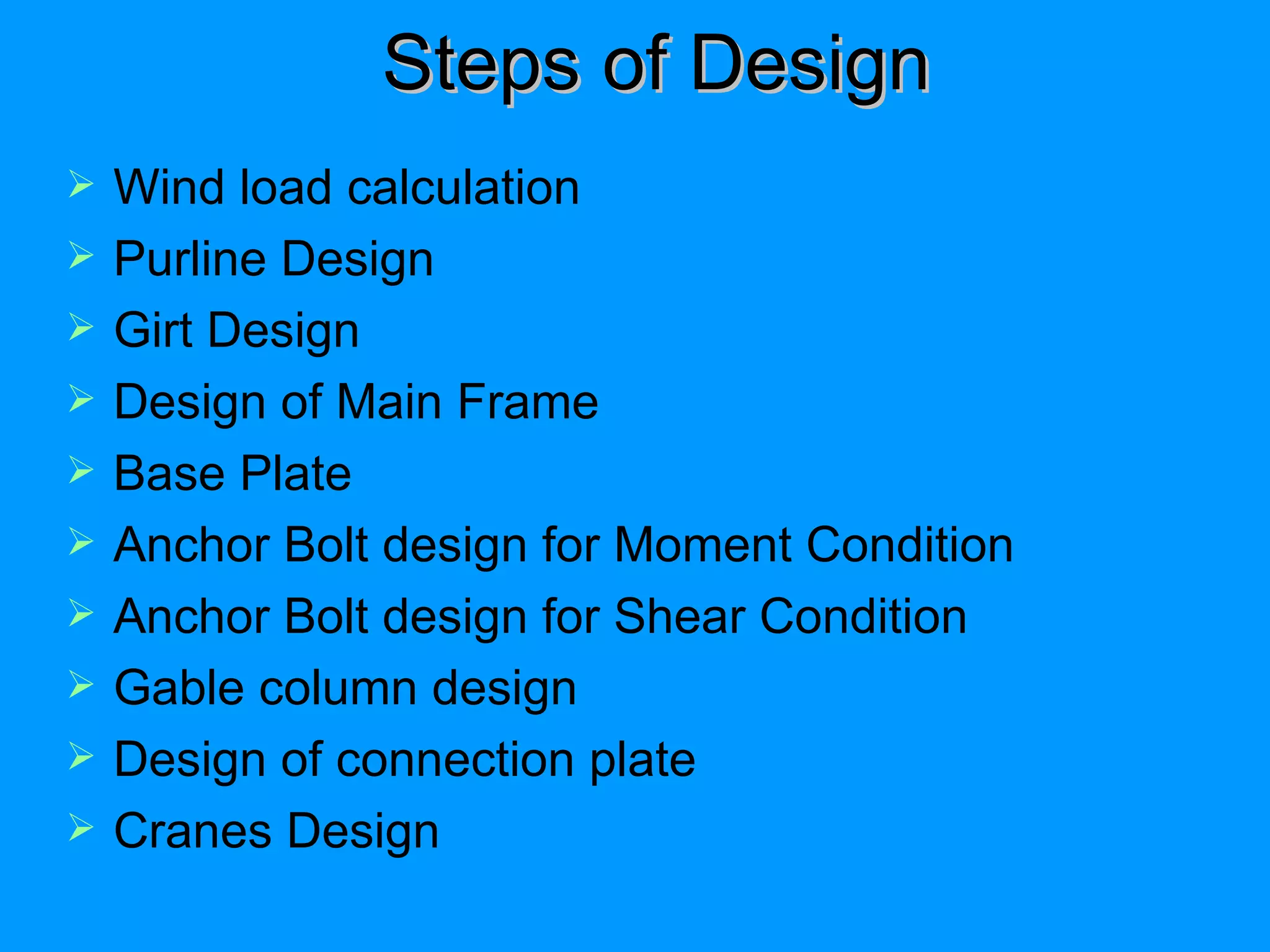
Calculation of wind loads and the systematic design process including purline and girt design, ensuring structural safety under various conditions.
Overview of the manufacturing lines for Pre-Engineered Building components, covering every step from built-up lines to sheeting.
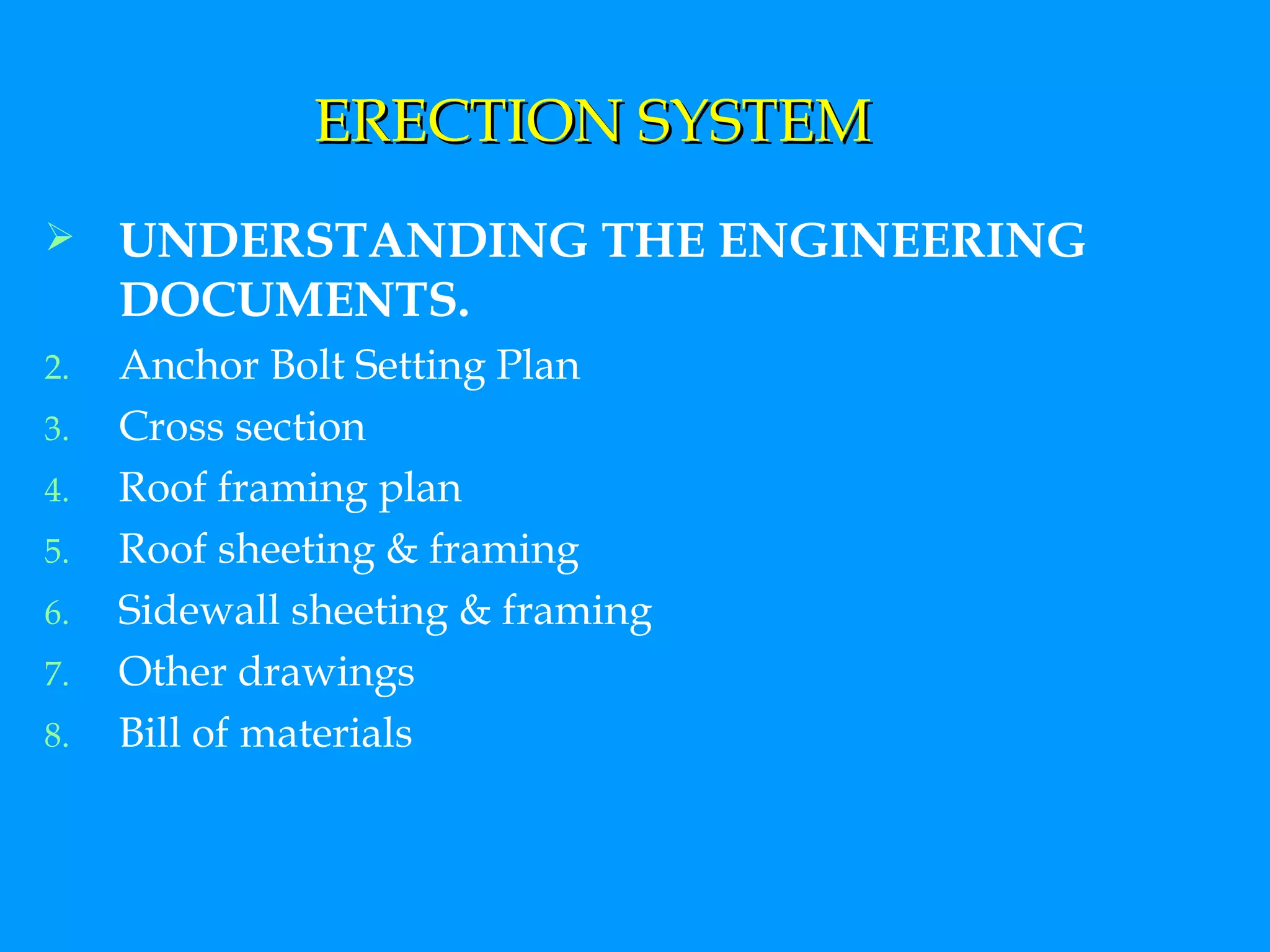
Steps involved in the erection of PEB structures, including pre-erection checks and the methods of assembling various building components.
PRE ENGINEERED BUILDINGSTailor made building based on client’s requirement & actual design calculations using tapered sections. A combination of built up section, hot rolled section, cold formed elements and profiled sheets Designing and casting is done in factory Building components are brought to site Then fixed/jointed at the site All connections are bolted.
2.
Steel was veryexpensive item in USA The concept of PEB originate from here. The idea was that section should be provided as per B.M.D.This lead to the saving in steel and development of PEB concept. BRIEF HISTORY
Self weight 30% lighter Primary Member is tapered section Secondary members are light weight rolled framed “Z” and “C” section Self weight More heavy Primary members are Hot rolled “I” section Secondary members are “I” or “C” section which are heavy in weight.
6.
Delivery – average6 to 8 weeks Foundation-simple design, easy to construct & light wt. Erection cost and time- accurately known Erection process is easy, fast, step by step Delivery- average 20 to 26 weeks Foundation- expensive, heavy foundation required. Erection cost and time- 20% more than PEB Erection process is slow and extensive field labor is required.
7.
Seismic Resistance- lowweight flexible frames offer higher resistance to seismic forces Overall price -30%lower architecture-achieved at low cast Seismic Resistance- rigid heavy weight structures do not perform well in seismic zones Overall price - Higher Price per square meter. Architecture- achieved at higher cost
8.
COMPONENTS Main FramePrimary Members Columns Rafters Secondary Members Purlins Girts Sheeting Roof Wall Fascias etc Accessories Ventilators Sky Lights Misc.
9.
10.
OTHER MAJOR COMPONENTSOF PEB CRANE BRACKETS & BEAMS MEZZANINE FLOORS STRUCTURAL PARTIONS FASCIAS CANOPIES
11.
DESIGN ISSUES STRUCTURALPLANNING FRAME CONFIGURATIONS TYPES OF LOADS & ASSESSMENT END CONDITIONS CRANES MEZANINES LOAD COMBINATIONS
12.
PRE-ENGINEERED BUILDINGS NOMENCLATURE– STANDARD FRAMING SYSTEMS TCCS = TAPERED COLUMN CLEAR SPAN TCMS-1 TAPERED COLUMN MULTI-SPAN WITH 1 INTERMEDIATE COLUMN .
13.
SSCS = SINGLESLOPE CLEAR SPAN . SSMS-1= SINGLE SLOPE MULTI-SPAN WITH 1 INTERMEDIATE COLUMN
14.
GUIDELINES FOR PEBDESIGN AT PROPOSAL STAGE ALL DESIGNS SHALL BE AS PER MBMA AMERICAN STANDARDS UNLESS CLIENT SPECIFIES AS PER IS CODE LIVE LOAD AS PER AMERICAN CODE = 0.57 KN/M^2 AND AS PER IS CODE = 0.75 KN/M^2. (REDUCTION IN LIVE LOAD TO BE INCORPORATED FOR BUILDINGS HAVING HIGHER SLOPES) AS PER AMERICAN CODE :HORIZONTAL DEFLECTION = L/180 & VERTICAL DEFLECTION=Eh/100 FOR MAIN FRAMES. WIND TERRAIN CATEGORY 3 IS TO BE SELECTED UNLESS MORE DATA IS AVAILABLE.
15.
CONTD…… IN AMERICANDESIGN , WIND COEFFICIENTS TO BE FOLLOWED AS GIVEN IN MBMA. IN IS DESIGN, INTERNAL & EXTERNAL BUILDING WIND COEFFICIENTS AS PER IS -875 (PART-3). GENERALLY BUILDINGS ARE TO BE DESIGNED AS PINNED EXCEPT FOR BUILDING SPAN >30M OR CRANE CAPACITY OF MORE THAN 5 TONS OR HEIGHT GREATER THAN 9 M STANDARD PURLIN LAPS SHOULD BE 385 mm
16.
Optimisation of frameBasic Frame Width of the frame = 38 m Height of the frame = 18m Length of the frame = 45 m Bay spacing l = 7 m Slop of roof i= 1:10 Wind speed v = 43 m/s Seismic zone = 4
17.
Varying of Widthof Frame Only Primary Frame Design Purline 250 X 2.5 mm 2 Spacing-1.5 7.67 kg/m Design Girt 200X1.75 mm 2 Spacing-1.5 6.09 kg/m
18.
Varying Height andwidth Only Primary Frame Design Purline 250 X 2.5 mm 2 Spacing-1.5 7.67 kg/m Spacing-1.5 Design Girt 250X2.0 mm 2 Spacing-1.5 6.09 kg/m Spacing-1.5
19.
Varying Bay lengthwith Height Total weight of Frame, Purline and Girt Heigth-6 Heigth-8 Heigth-9 Purline Girt Purline Girt Pur line Girt 6 Z 200X1.75 Spacing-1.5 Z 200X1.75 Spacing-1.5 Z 200X1.75 Spacing-1.5 Z 200X1.75 Spacing-1.5 Z 200X1.75 Spacing-1.5 Z 200X1.75 Spacing-1.5 7 Z 250X 2.0 Spacing-1.5 Z 250X1.75 Spacing-1.35 Z 250X 2.0 Spacing-1.5 Z 250X1.75 Spacing-1.35 Z 250X 2.0 Spacing-1.5 Z 250X1.75 Spacing-1.35 8 Z 250 X 2.5 Spacing-1.5 Z 250 X 2.5 Spacing-1.5 Z 250 X 2.5 Spacing-1.5 Z 250 X 2.5 Spacing-1.5 Z 250 X 2.5 Spacing-1.5 Z 250 X 2.5 Spacing-1.5 9 C250 X 2.5 Spacing-1.4 C 250 X 2.5 Spacing-1.35 C250 X 2.5 Spacing-1.4 C 250 X 2.5 Spacing-1.35 C250 X 2.5 Spacing-1.4 C 250 X 2.5 Spacing-1.35 10 C 250 X 2.5 Spacing-1.0 C 250 X 2.5 Spacing-1.0 C 250 X 2.5 Spacing-1.0 C 250 X 2.5 Spacing-1.0 C 250 X 2.5 Spacing-1.0 C 250 X 2.5 Spacing-1.0
20.
Varying bay lengthwith width Total weight of Frame, Purline and Girt Heigth-6 Heigth-8 Heigth-9 Purline Girt Purline Girt Purline Girt 6 Z 200X1.75 Spacing-1.5 Z 200X1.75 Spacing-1.5 Z 200X1.75 Spacing-1.5 Z 200X1.75 Spacing-1.5 Z 200X1.75 Spacing-1.5 Z 200X1.75 Spacing-1.5 7 Z 250X 2.0 Spacing-1.5 Z 250X1.75 Spacing-1.35 Z 250X 2.0 Spacing-1.5 Z 250X1.75 Spacing-1.35 Z 250X 2.0 Spacing-1.5 Z 250X1.75 Spacing-1.35 8 Z 250 X 2.5 Spacing-1.5 Z 250 X 2.5 Spacing-1.5 Z 250 X 2.5 Spacing-1.5 Z 250 X 2.5 Spacing-1.5 Z 250 X 2.5 Spacing-1.5 Z 250 X 2.5 Spacing-1.5 9 C250 X 2.5 Spacing-1.4 C 250 X 2.5 Spacing-1.35 C250 X 2.5 Spacing-1.4 C 250 X 2.5 Spacing-1.35 C250 X 2.5 Spacing-1.4 C 250 X 2.5 Spacing-1.35 10 C 250 X 2.5 Spacing-1.0 C 250 X 2.5 Spacing-1.0 C 250 X 2.5 Spacing-1.0 C 250 X 2.5 Spacing-1.0 C 250 X 2.5 Spacing-1.0 C 250 X 2.5 Spacing-1.0
21.
Varying wind speedwith width Total weight of Frame, Purline and Girt wind Width-20m Width-35 speed Purline Girt Purline Girt 33 Z 200 X 1.75 Spacing-1.5 Z 200X1.75 Spacing-1.5 Z 200 X 1.75 Spacing-1.5 Z 200X1.75 Spacing-1.5 39 Z 200 X 2.0 Spacing-1.5 Z 200X2.0 Spacing-1.5 Z 200 X 2.0 Spacing-1.5 Z 200X2.0 Spacing-1.5 43 Z 250 X 2 Spacing-1.5 Z 250X2.0 Spacing-1.4 Z 250 X 2 Spacing-1.5 Z 250X2.0 Spacing-1.4 47 Z 250 X 2.5 Spacing-1.5 Z 250X2.0 Spacing-1.45 Z 250 X 2.5 Spacing-1.5 Z 250X2.0 Spacing-1.45 50 Z 250 X 2.5 Spacing-1.5 Z 250 X 2.5 Spacing-1.5 Z 250 X 2.5 Spacing-1.5 Z 250 X 2.5 Spacing-1.5 55 C 250 X 2.5 Spacing-1.35 C 250 X 2.5 Spacing-1.5 C 250 X 2.5 Spacing-1.35 C 250 X 2.5 Spacing-1.5
22.
Steps of DesignWind load calculation Purline Design Girt Design Design of Main Frame Base Plate Anchor Bolt design for Moment Condition Anchor Bolt design for Shear Condition Gable column design Design of connection plate Cranes Design
PROCESSES PEB BUILTUP LINE COLD FORM LINE SHEETING PRIMARY MEMBERS CKD C & Z PURLINS LINE HR SECTIONS & MISCELLANEOUS PARTS ROOF & WALL SHEETING GUTTER, FLASHINGS, TRIMS, ETC CKD CKD CKD ACCESSORIES SHIPMENT
27.
ERECTION SYSTEM UNDERSTANDINGTHE ENGINEERING DOCUMENTS. Anchor Bolt Setting Plan Cross section Roof framing plan Roof sheeting & framing Sidewall sheeting & framing Other drawings Bill of materials
28.
CONTD… Preparation forErection Pre Erection checks Receiving Materials at site Unloading Containers Erection of the Framing Preparation of the First Bay Main frames Mezzanine floors Crane Beams
29.
CONTD…. Sheeting &Trimming Sheeting preparation Sheeting the walls Sheeting the roofs Miscellaneous trimmings Fascia