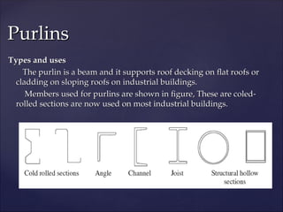
Types and uses
Typesand uses
The purlin is a beam and it supports roof decking on flat roofs or
The purlin is a beam and it supports roof decking on flat roofs or
cladding on sloping roofs on industrial buildings.
cladding on sloping roofs on industrial buildings.
Members used for purlins are shown in figure, These are coled-
Members used for purlins are shown in figure, These are coled-
rolled sections are now used on most industrial buildings.
rolled sections are now used on most industrial buildings.
Purlins
Purlins
6.
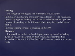
Loading
Loading
The weight ofroofing are varies from 0.3 to 1.0 KN/m
The weight of roofing are varies from 0.3 to 1.0 KN/m2
2
-
Purlin carrying sheeting are usually spaced from 1.4 – 2.0 m centers.
Purlin carrying sheeting are usually spaced from 1.4 – 2.0 m centers.
Joists carrying roof decking can be spaced at larger centers up to 6 m
Joists carrying roof decking can be spaced at larger centers up to 6 m
or more, depending on the thickness of decking sheet and depth of
or more, depending on the thickness of decking sheet and depth of
profile.
profile.
-
Imposed loading for roof is specified in BS 6399
Imposed loading for roof is specified in BS 6399
-
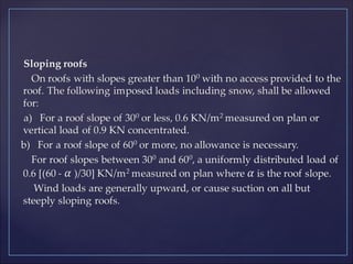
Flat roofs
Flat roofs
Imposed load on flat roof and sloping roofs up to and including
Imposed load on flat roof and sloping roofs up to and including
10
100
0
is 1.5 KN/m
is 1.5 KN/m2
2
measured on plan or 1.8 KN concentrated for
measured on plan or 1.8 KN concentrated for
accessible roofs, and 0.6 KN/m
accessible roofs, and 0.6 KN/m2
2
or 0.9 KN concentrated for no access
or 0.9 KN concentrated for no access
roofs.
roofs.
9.
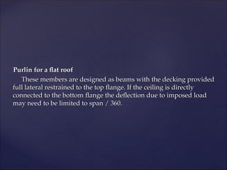
Purlin for aflat roof
Purlin for a flat roof
These members are designed as beams with the decking provided
These members are designed as beams with the decking provided
full lateral restrained to the top flange. If the ceiling is directly
full lateral restrained to the top flange. If the ceiling is directly
connected to the bottom flange the deflection due to imposed load
connected to the bottom flange the deflection due to imposed load
may need to be limited to span / 360.
may need to be limited to span / 360.
10.
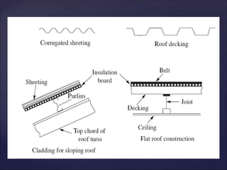
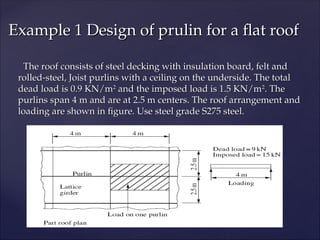
The roof consistsof steel decking with insulation board, felt and
The roof consists of steel decking with insulation board, felt and
rolled-steel, Joist purlins with a ceiling on the underside. The total
rolled-steel, Joist purlins with a ceiling on the underside. The total
dead load is 0.9 KN/m
dead load is 0.9 KN/m2
2
and the imposed load is 1.5 KN/m
and the imposed load is 1.5 KN/m2
2
. The
. The
purlins span 4 m and are at 2.5 m centers. The roof arrangement and
purlins span 4 m and are at 2.5 m centers. The roof arrangement and
loading are shown in figure. Use steel grade S275 steel.
loading are shown in figure. Use steel grade S275 steel.
Example 1 Design of prulin for a flat roof
Example 1 Design of prulin for a flat roof
11.
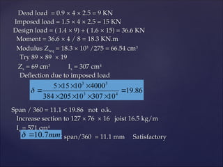
Dead load =0.9
Dead load = 0.9 ×
× 4
4 ×
× 2.5 = 9 KN
2.5 = 9 KN
Imposed load = 1.5
Imposed load = 1.5 ×
× 4
4 ×
× 2.5 = 15 KN
2.5 = 15 KN
Design load = ( 1.4
Design load = ( 1.4 ×
× 9) + ( 1.6
9) + ( 1.6 ×
× 15) = 36.6 KN
15) = 36.6 KN
Moment = 36.6
Moment = 36.6 ×
× 4 / 8 = 18.3 KN.m
4 / 8 = 18.3 KN.m
Modulus Z
Modulus Zreq
req = 18.3
= 18.3 ×
× 10
103
3
/275 = 66.54 cm
/275 = 66.54 cm3
3
Try 89
Try 89 ×
× 89 × 19
89 × 19
Z
Zx
x = 69 cm
= 69 cm3
3
I
Ix
x = 307 cm
= 307 cm4
4
Deflection due to imposed load
Deflection due to imposed load
Span / 360 = 11.1 < 19.86 not o.k.
Span / 360 = 11.1 < 19.86 not o.k.
Increase section to 127
Increase section to 127 ×
× 76 × 16 joist 16.5 kg/m
76 × 16 joist 16.5 kg/m
I
Ix
x = 571 cm
= 571 cm4
4
< span/360 = 11.1 mm Satisfactory
< span/360 = 11.1 mm Satisfactory
86
.
19
10
307
10
205
384
4000
10
15
5
4
3
3
3
mm
7
.
10
12.
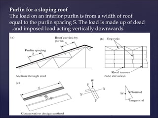
Purlin for asloping roof
The load on an interior purlin is from a width of roof
equal to the purlin spacing S. The load is made up of dead
and imposed load acting vertically downwards
.
13.
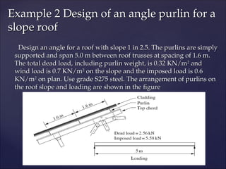
Design an anglefor a roof with slope 1 in 2.5. The purlins are simply
Design an angle for a roof with slope 1 in 2.5. The purlins are simply
supported and span 5.0 m between roof trusses at spacing of 1.6 m.
supported and span 5.0 m between roof trusses at spacing of 1.6 m.
The total dead load, including purlin weight, is 0.32 KN/m
The total dead load, including purlin weight, is 0.32 KN/m2
2
and
and
wind load is 0.7 KN/m
wind load is 0.7 KN/m2
2
on the slope and the imposed load is 0.6
on the slope and the imposed load is 0.6
KN/m
KN/m2
2
on plan. Use grade S275 steel. The arrangement of purlins on
on plan. Use grade S275 steel. The arrangement of purlins on
the roof slope and loading are shown in the figure
the roof slope and loading are shown in the figure
Example 2 Design of an angle purlin for a
Example 2 Design of an angle purlin for a
slope roof
slope roof
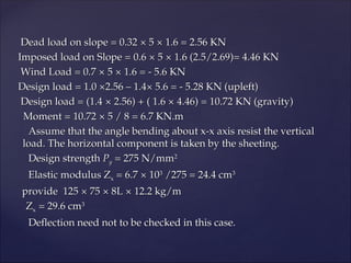
14.
Dead load onslope = 0.32
Dead load on slope = 0.32 ×
× 5
5 ×
× 1.6 = 2.56 KN
1.6 = 2.56 KN
Imposed load on Slope = 0.6
Imposed load on Slope = 0.6 ×
× 5
5 ×
× 1.6 (2.5/2.69)= 4.46 KN
1.6 (2.5/2.69)= 4.46 KN
Wind Load = 0.7
Wind Load = 0.7 ×
× 5
5 ×
× 1.6 = - 5.6 KN
1.6 = - 5.6 KN
Design load = 1.0 ×2.56 – 1.4× 5.6 = - 5.28 KN (upleft)
Design load = 1.0 ×2.56 – 1.4× 5.6 = - 5.28 KN (upleft)
Design load = (1.4
Design load = (1.4 ×
× 2.56) + ( 1.6
2.56) + ( 1.6 ×
× 4.46) = 10.72 KN (gravity)
4.46) = 10.72 KN (gravity)
Moment = 10.72
Moment = 10.72 ×
× 5 / 8 = 6.7 KN.m
5 / 8 = 6.7 KN.m
Assume that the angle bending about x-x axis resist the vertical
Assume that the angle bending about x-x axis resist the vertical
load. The horizontal component is taken by the sheeting.
load. The horizontal component is taken by the sheeting.
Design strength
Design strength P
Py
y = 275 N/mm
= 275 N/mm2
2
Elastic modulus Z
Elastic modulus Zx
x = 6.7
= 6.7 ×
× 10
103
3
/275 = 24.4 cm
/275 = 24.4 cm3
3
provide 125
provide 125 ×
× 75
75 ×
× 8L
8L ×
× 12.2 kg/m
12.2 kg/m
Z
Zx
x = 29.6 cm
= 29.6 cm3
3
Deflection need not to be checked in this case.
Deflection need not to be checked in this case.
15.
Design of purlinsto BS 5950
Design of purlins to BS 5950
The code states that the cladding may be assumed to provide
The code states that the cladding may be assumed to provide
restraint to an angle section or to the face against which it is
restraint to an angle section or to the face against which it is
connected in the case of other section.
connected in the case of other section.
The empirical design method is set out in the code, and the general
The empirical design method is set out in the code, and the general
requirements are:
requirements are:
1- The member should be of steel to a minimum of grade S275
1- The member should be of steel to a minimum of grade S275
2- Unfactored loads are used in the design
2- Unfactored loads are used in the design
3- The span is not to exceed 6.5 m center to center of main supports
3- The span is not to exceed 6.5 m center to center of main supports
4- If the purlin spans one bay it must be connected by at least two
4- If the purlin spans one bay it must be connected by at least two
bolts at each ends
bolts at each ends
5- If the purlins are continuous over two or more bays with staggered
5- If the purlins are continuous over two or more bays with staggered
joints in adjacent lines, at least one end of any single bay member
joints in adjacent lines, at least one end of any single bay member
should be connected by two or more bolts.
should be connected by two or more bolts.
16.
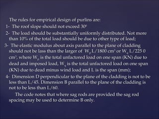
The rules forempirical design of purlins are:
The rules for empirical design of purlins are:
1- The roof slope should not exceed 30
1- The roof slope should not exceed 300
0
2- The load should be substantially uniformly distributed. Not more
2- The load should be substantially uniformly distributed. Not more
than 10% of the total load should be due to other type of load;
than 10% of the total load should be due to other type of load;
3- The elastic modulus about axis parallel to the plane of cladding
3- The elastic modulus about axis parallel to the plane of cladding
should not be lass than the larger of W
should not be lass than the larger of Wp
p L/1800 cm
L/1800 cm3
3
or W
or Wq
q L/225 0
L/225 0
cm
cm3
3
, where W
, where Wp
p is the total unfactored load on one span (KN) due to
is the total unfactored load on one span (KN) due to
dead and imposed load, W
dead and imposed load, Wq
q is the total unfactored load on one span
is the total unfactored load on one span
(KN) due to dead minus wind load and L is the span (mm);
(KN) due to dead minus wind load and L is the span (mm);
4- Dimension D perpendicular to the plane of the cladding is not to be
4- Dimension D perpendicular to the plane of the cladding is not to be
less than L/45. Dimension B parallel to the plane of the cladding is
less than L/45. Dimension B parallel to the plane of the cladding is
not to be less than L/60.
not to be less than L/60.
The code notes that where sag rods are provided the sag rod
The code notes that where sag rods are provided the sag rod
spacing may be used to determine B only.
spacing may be used to determine B only.
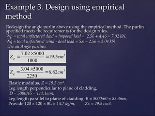
18.
Redesign the anglepurlin above using the empirical method. The purlin
Redesign the angle purlin above using the empirical method. The purlin
specified meets the requirements for the design rules.
specified meets the requirements for the design rules.
Wp = total unfactored dead + imposed load = 2.56 + 4.46 = 7.02 kN,
Wp = total unfactored dead + imposed load = 2.56 + 4.46 = 7.02 kN,
Wq = total unfactored wind - dead load = 5.6 – 2.56 = 3.04 kN
Wq = total unfactored wind - dead load = 5.6 – 2.56 = 3.04 kN
Use an Angle purlins:
Use an Angle purlins:
Elastic modulus,
Elastic modulus, Z = 19.5 cm
Z = 19.5 cm3
3
.
.
Leg length perpendicular to plane of cladding,
Leg length perpendicular to plane of cladding,
D = 5000/45 = 111.1mm,
D = 5000/45 = 111.1mm,
Leg length parallel to plane of cladding,
Leg length parallel to plane of cladding, B = 5000/60 = 83.3mm,
B = 5000/60 = 83.3mm,
Provide 120 × 120 × 8L × 14
Provide 120 × 120 × 8L × 14.7 kg/m, Zx = 29.5 cm3.
.7 kg/m, Zx = 29.5 cm3.
Example 3. Design using empirical
Example 3. Design using empirical
method
method
3
5
.
19
1800
5000
02
.
7
cm
Zp
3
82
.
6
2250
5000
04
.
3
cm
Zq
19.
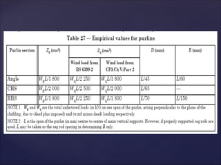
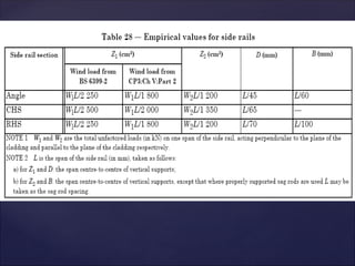
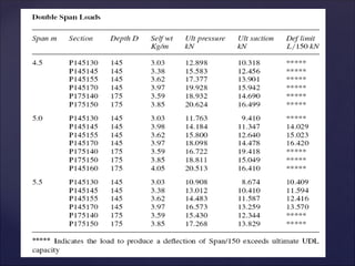
Cold-rolled purlins
Cold-rolled purlins
cold-rolledpurlins are almost exclusively adopted for industrial
cold-rolled purlins are almost exclusively adopted for industrial
buildings. The multi-beam cold formed section and ultimate loads for
buildings. The multi-beam cold formed section and ultimate loads for
double-span purlins for a limit range of purlins are shown in Table
double-span purlins for a limit range of purlins are shown in Table
below. Note for use of the table are:
below. Note for use of the table are:
1- The loads tables show the ultimate loads that can be applied. The
1- The loads tables show the ultimate loads that can be applied. The
section self-weight has not been deducted. Loadings have also been
section self-weight has not been deducted. Loadings have also been
tabulated that will produce the noted deflection
tabulated that will produce the noted deflection
2- The loads given are based on lateral restraint being provided to the
2- The loads given are based on lateral restraint being provided to the
top flange by the cladding
top flange by the cladding
3- The values given are also the ultimate uplift load due to wind.
3- The values given are also the ultimate uplift load due to wind.
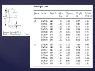
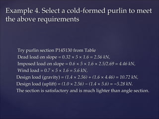
21.
Try purlin sectionP145130 from Table
Try purlin section P145130 from Table
Dead load on slope = 0
Dead load on slope = 0.32 × 5 × 1.6 = 2.56 kN,
.32 × 5 × 1.6 = 2.56 kN,
Imposed load on slope = 0
Imposed load on slope = 0.6 × 5 × 1.6 × 2.5/2.69 = 4.46 kN,
.6 × 5 × 1.6 × 2.5/2.69 = 4.46 kN,
Wind load = 0
Wind load = 0.7 × 5 × 1.6 = 5.6 kN,
.7 × 5 × 1.6 = 5.6 kN,
Design load (gravity) =
Design load (gravity) = (1.4 × 2.56) + (1.6 × 4.46) = 10.72 kN,
(1.4 × 2.56) + (1.6 × 4.46) = 10.72 kN,
Design load (uplift) =
Design load (uplift) = (1.0 × 2.56) − (1.4 × 5.6) = −5.28 kN.
(1.0 × 2.56) − (1.4 × 5.6) = −5.28 kN.
The section is satisfactory and is much lighter than angle section.
The section is satisfactory and is much lighter than angle section.
Example 4. Select a cold-formed purlin to meet
Example 4. Select a cold-formed purlin to meet
the above requirements
the above requirements
22.
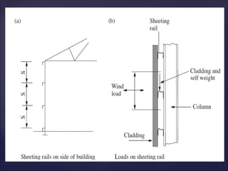
Sheeting rails supportcladding on walls and the sections used are
Sheeting rails support cladding on walls and the sections used are
the same as those for the purlins.
the same as those for the purlins.
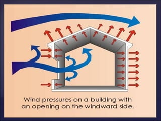
Loading
Loading
Sheeting rails carry a horizontal load from the wind and a vertical
Sheeting rails carry a horizontal load from the wind and a vertical
one from self-weight and the weight of the cladding. The cladding
one from self-weight and the weight of the cladding. The cladding
materials are the same as used for sloping roofs (metal sheeting on
materials are the same as used for sloping roofs (metal sheeting on
insulation board).Wind loads are estimated using BS 6399: Part 2. The
insulation board).Wind loads are estimated using BS 6399: Part 2. The
wind may act in either direction due to pressure or suction on the
wind may act in either direction due to pressure or suction on the
building walls.
building walls.
Sheeting Rails
Sheeting Rails
25.
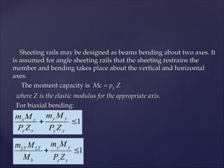
Sheeting rails maybe designed as beams bending about two axes. It
Sheeting rails may be designed as beams bending about two axes. It
is assumed for angle sheeting rails that the sheeting restrains the
is assumed for angle sheeting rails that the sheeting restrains the
member and bending takes place about the vertical and horizontal
member and bending takes place about the vertical and horizontal
axes.
axes.
The moment capacity is
The moment capacity is Mc = p
Mc = py
y Z
Z
where Z is the elastic modulus for the appropriate axis.
where Z is the elastic modulus for the appropriate axis.
For biaxial bending:
For biaxial bending:
1
y
y
y
y
x
y
x
x
Z
P
M
m
Z
P
M
m
1
y
y
y
y
b
LT
LT
Z
P
M
m
M
M
m
26.
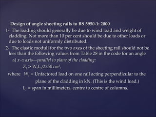
Design of anglesheeting rails to BS 5950-1: 2000
Design of angle sheeting rails to BS 5950-1: 2000
1- The loading should generally be due to wind load and weight of
1- The loading should generally be due to wind load and weight of
cladding. Not more than 10 per cent should be due to other loads or
cladding. Not more than 10 per cent should be due to other loads or
due to loads not uniformly distributed.
due to loads not uniformly distributed.
2- The elastic moduli for the two axes of the sheeting rail should not be
2- The elastic moduli for the two axes of the sheeting rail should not be
less than the following values from Table 28 in the code for an angle
less than the following values from Table 28 in the code for an angle
a)
a) x–x axis—parallel to plane of the cladding:
x–x axis—parallel to plane of the cladding:
Z
Z1
1 > W
> W1
1L
L1
1/2250 cm
/2250 cm3
3
,
,
where
where W
W1
1 =
= Unfactored load on one rail acting perpendicular to the
Unfactored load on one rail acting perpendicular to the
plane of the cladding in kN. (This is the wind load.)
plane of the cladding in kN. (This is the wind load.)
L
L1
1 =
= span in millimeters, centre to centre of columns.
span in millimeters, centre to centre of columns.
27.
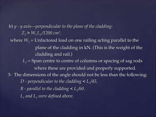
b)
b) y -y axis—perpendicular to the plane of the cladding:
y - y axis—perpendicular to the plane of the cladding:
Z
Z2
2 > W
> W2
2 L
L2
2 /1200 cm
/1200 cm3
3
,
,
where
where W
W2
2 =
= Unfactored load on one railing acting parallel to the
Unfactored load on one railing acting parallel to the
plane of the cladding in kN. (This is the weight of the
plane of the cladding in kN. (This is the weight of the
cladding and rail.)
cladding and rail.)
L
L2
2 =
= Span centre to centre of columns or spacing of sag rods
Span centre to centre of columns or spacing of sag rods
where these are provided and properly supported.
where these are provided and properly supported.
3- The dimensions of the angle should not be less than the following:
3- The dimensions of the angle should not be less than the following:
D - perpendicular to the cladding < L
D - perpendicular to the cladding < L1
1/45,
/45,
B - parallel to the cladding < L
B - parallel to the cladding < L2
2/60.
/60.
L
L1
1 and L
and L2
2 were defined above.
were defined above.
29.
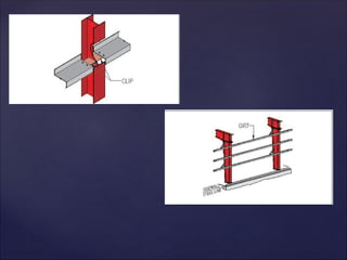
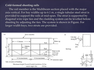
Cold-formed sheeting rails
Cold-formedsheeting rails
The rail member is the Multibeam section placed with the major
The rail member is the Multibeam section placed with the major
axis vertical. For bay widths up to 6.1 m, a single tubular steel strut is
axis vertical. For bay widths up to 6.1 m, a single tubular steel strut is
provided to support the rails at mid-span. The strut is supported by
provided to support the rails at mid-span. The strut is supported by
diagonal wire rope ties and the cladding system can be levelled before
diagonal wire rope ties and the cladding system can be levelled before
sheeting by adjusting the ties. The system is shown in Figure. For
sheeting by adjusting the ties. The system is shown in Figure. For
larger width bays, two struts are provided.
larger width bays, two struts are provided.
31.
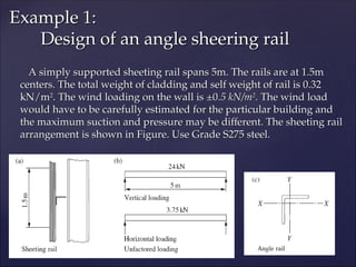
A simply supportedsheeting rail spans 5m. The rails are at 1.5m
A simply supported sheeting rail spans 5m. The rails are at 1.5m
centers. The total weight of cladding and self weight of rail is 0.32
centers. The total weight of cladding and self weight of rail is 0.32
kN/m
kN/m2
2
. The wind loading on the wall is ±0
. The wind loading on the wall is ±0.5 kN/m
.5 kN/m2
2
.
. The wind load
The wind load
would have to be carefully estimated for the particular building and
would have to be carefully estimated for the particular building and
the maximum suction and pressure may be different. The sheeting rail
the maximum suction and pressure may be different. The sheeting rail
arrangement is shown in Figure. Use Grade S275 steel.
arrangement is shown in Figure. Use Grade S275 steel.
Example 1:
Example 1:
Design of an angle sheering rail
Design of an angle sheering rail
32.
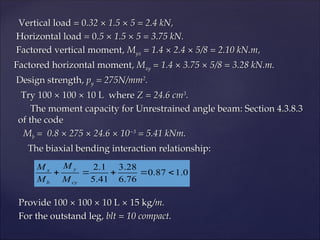
Vertical load =0
Vertical load = 0.32 × 1.5 × 5 = 2.4 kN,
.32 × 1.5 × 5 = 2.4 kN,
Horizontal load = 0
Horizontal load = 0.5 × 1.5 × 5 = 3.75 kN.
.5 × 1.5 × 5 = 3.75 kN.
Factored vertical moment,
Factored vertical moment, M
Myx
yx = 1.4 × 2.4 × 5/8 = 2.10 kN.m,
= 1.4 × 2.4 × 5/8 = 2.10 kN.m,
Factored horizontal moment,
Factored horizontal moment, M
Mxy
xy = 1.4 × 3.75 × 5/8 = 3.28 kN.m.
= 1.4 × 3.75 × 5/8 = 3.28 kN.m.
Design strength,
Design strength, p
py
y = 275N/mm
= 275N/mm2
2
.
.
Try 100 × 100 × 10 L where
Try 100 × 100 × 10 L where Z = 24.6 cm
Z = 24.6 cm3
3
.
.
The moment capacity for Unrestrained angle beam: Section 4.3.8.3
The moment capacity for Unrestrained angle beam: Section 4.3.8.3
of the code
of the code
M
Mb
b = 0.8 × 275 × 24.6 × 10
= 0.8 × 275 × 24.6 × 10−3
−3
= 5.41 kNm.
= 5.41 kNm.
The biaxial bending interaction relationship:
The biaxial bending interaction relationship:
Provide 100 × 100 × 10 L × 15 kg
Provide 100 × 100 × 10 L × 15 kg/m.
/m.
For the outstand leg,
For the outstand leg, blt = 10 compact.
blt = 10 compact.
0
.
1
87
.
0
76
.
6
28
.
3
41
.
5
1
.
2
cy
y
b
x
M
M
M
M
33.
Redesign the anglesheeting rail above using the empirical method
Redesign the angle sheeting rail above using the empirical method
from BS 5950.
from BS 5950.
Unfactored wind load
Unfactored wind load W
W1
1 = 3.75 kN.
= 3.75 kN.
Elastic modulus
Elastic modulus Z
Z1
1 = Z
= Zy
y = 3.75 × 5000/2250 = 8.33 cm
= 3.75 × 5000/2250 = 8.33 cm3
3
.
.
Unfactored dead load
Unfactored dead load W
W2
2 = 2.4 kN.
= 2.4 kN.
Elastic modulus
Elastic modulus Z
Z2
2 = Z
= Zx
x = 2.4 × 5000/1200 = 10.0 cm
= 2.4 × 5000/1200 = 10.0 cm3
3
.
.
Dimensions specified are to be
Dimensions specified are to be
D - perpendicular to cladding <5000/45 = 111.1mm,
D - perpendicular to cladding <5000/45 = 111.1mm,
B - parallel to cladding <5000/60 = 83.3mm.
B - parallel to cladding <5000/60 = 83.3mm.
120 × 120 × 8 L is the smallest angle to meet all the requirements.
120 × 120 × 8 L is the smallest angle to meet all the requirements.
Example 2. Design using empirical
Example 2. Design using empirical
method
method
34.
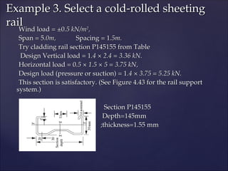
Wind load =±0
Wind load = ±0.5 kN/m
.5 kN/m2
2
,
,
Span = 5
Span = 5.0m,
.0m, Spacing = 1
Spacing = 1.5m.
.5m.
Try cladding rail section P145155 from Table
Try cladding rail section P145155 from Table
Design Vertical load = 1
Design Vertical load = 1.4 × 2.4 = 3.36 kN.
.4 × 2.4 = 3.36 kN.
Horizontal load = 0
Horizontal load = 0.5 × 1.5 × 5 = 3.75 kN,
.5 × 1.5 × 5 = 3.75 kN,
Design load (pressure or suction) = 1
Design load (pressure or suction) = 1.4 × 3.75 = 5.25 kN.
.4 × 3.75 = 5.25 kN.
This section is satisfactory. (See Figure 4.43 for the rail support
This section is satisfactory. (See Figure 4.43 for the rail support
system.)
system.)
Section P145155
Section P145155
Depth=145mm
Depth=145mm
;thickness=1.55 mm
;thickness=1.55 mm
Example 3. Select a cold-rolled sheeting
Example 3. Select a cold-rolled sheeting
rail
rail