Download to read offline
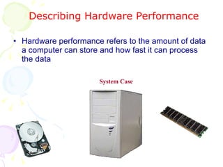
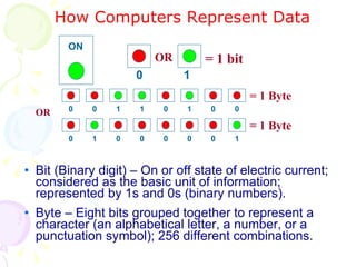
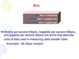
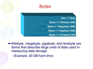
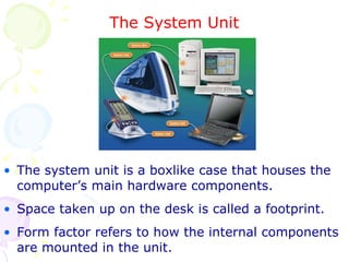
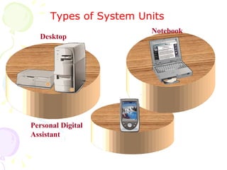
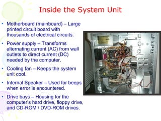
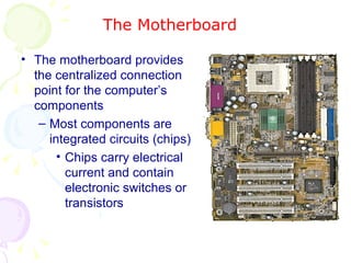
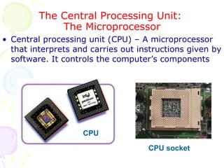
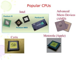
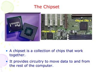
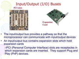
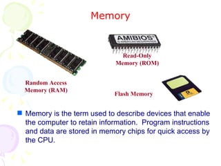
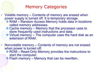

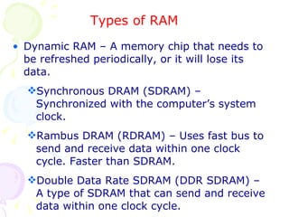
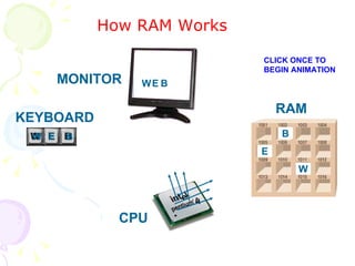


This document summarizes the key components of a computer system. It describes the system unit case and internal components like the motherboard, CPU, memory, and storage drives. It explains how bits and bytes represent data and how components like the control unit, ALU, and registers work together in the CPU's processing cycle. Connection ports on the outside of the system unit and the functions of common components are also outlined.