summer training report ntpc anta
•
5 likes•1,283 views

NTPC Anta is a 419.33 MW combined cycle natural gas power plant located in Anta, Rajasthan. It was the first combined cycle power project set up by NTPC and consists of 3 gas turbine units of 88.71 MW each and 1 steam turbine unit of 153.2 MW. Natural gas is supplied via a pipeline while backup fuel is naphtha delivered by tankers. The plant supplies power to several northern Indian states including Uttar Pradesh, Jammu and Kashmir, Himachal Pradesh, and Rajasthan.

More Related Content
What's hot
What's hot (20)
Viewers also liked
Viewers also liked (20)
Similar to summer training report ntpc anta
Similar to summer training report ntpc anta (20)
Recently uploaded
Recently uploaded (20)
summer training report ntpc anta
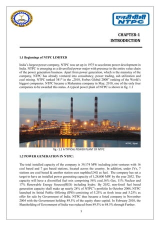
- 1. 1 CHAPTER-1 IINNTTRROODDUUCCTTIIOONN 1.1 Beginnings of NTPC LIMITED India’s largest power company, NTPC was set up in 1975 to accelerate power development in India. NTPC is emerging as a diversified power major with presence in the entire value chain of the power generation business. Apart from power generation, which is the mainstay of the company, NTPC has already ventured into consultancy, power trading, ash utilization and coal mining. NTPC ranked 341st in the „2010, Forbes Global 2000‟ ranking of the World’s biggest companies. NTPC became a Maharatna company in May, 2010, one of the only four companies to be awarded this status. A typical power plant of NTPC is shown in fig. 1.1 fig.- 1.1 A TYPICAL POWER PLANT OF NTPC 1.2 POWER GENERATION IN NTPC: The total installed capacity of the company is 39,174 MW including joint ventures with 16 coal based and 7 gas based stations, located across the country. In addition, under JVs, 7 stations are coal based & another station uses naphtha/LNG as fuel. The company has set a target to have an installed power generating capacity of 1,28,000 MW by the year 2032. The capacity will have a diversified fuel mix comprising 56% coal,16% Gas, 11% Nuclear and 17% Renewable Energy Sources(RES) including hydro. By 2032, non-fossil fuel based generation capacity shall make up nearly 28% of NTPC‟s portfolio In October 2004, NTPC launched its Initial Public Offering (IPO) consisting of 5.25% as fresh issue and 5.25% as offer for sale by Government of India. NTPC thus became a listed company in November 2004 with the Government holding 89.5% of the equity share capital. In February 2010, the Shareholding of Government of India was reduced from 89.5% to 84.5% through Further.
- 2. 2 1.3 JOURNEY OF NTPC:
- 3. 3 1.4NTPC Plants and their capacity: 1.4.1 Installed capacity: Present installed capacity of NTPC is 47,228 MW (including 6,966 MW through JVs/Subsidiaries) comprising of 44 NTPC Stations (18 Coal based stations, 7 combined cycle gas/liquid fuel based stations, 1 Hydro based station), 9 Joint Venture stations (8 coal based and one gas based) and 9 renewable energy projects. Installed capacity of NTPC is shown in table no. 1.1. TABLE 1.1 INSTALLED CAPACITY 1.4.2 Coal Based Power Stations: NTPC is the largest thermal power generating company in the country with a coal based installed capacity of 35,085 MW. Coal based power stations are shown in table 1.2 and 1.3 . Table 1.2 Coal based power stations owned by NTPC S. N o. COAL BASED POWER STATIONS STATE COMMISSIONED CAPACITY(MW) 1. Singrauli Uttar Pradesh 2,000 2. Korba Chhattisgar h 2,600 3. Ramagundam Telangana 2,600 4. Farakka West Bengal 2,100
- 4. 4 Table 1.3 Coal Based Joint Ventures/Subsidiaries: 5. Vindhyachal Madhya Pradesh 4,760 6. Rihand Uttar Pradesh 3,000 7. Kahalgaon Bihar 2,340 8. Dadri Uttar Pradesh 1,820 9. TalcherKaniha Orissa 3,000 10 . Feroze Gandhi, Unchahar Uttar Pradesh 1,050 11 . Talcher Thermal Orissa 460 12 . Simhadri Andhra Pradesh 2,000 13 . Tanda Uttar Pradesh 440 14 . Badarpur Delhi 705 15 . Sipat Chhattisgar h 2,980 16 . Mauda Maharashta 1,660 17 . Barh Bihar 1320 18 . Bongaigaon Assam 250 Total 35,085
- 5. 5 1.4.3 Gas Based Power Stations The details of NTPC gas based power stations is given in table 1.4 and 1.5. Table 1.4Gas Based Power Stations owned by NTPC Table 1.5 Gas Based Joint Ventures/Subsidiaries 1.4.4 Hydro Based Power Projects: NTPC has increased thrust on hydro development for a balanced portfolio for long term sustainability. Details are given below in table 1.6. Table 1.6 Hydro Based Power Projects
- 6. 6 1.4.5 Renewable Energy Projects Renewable energy technologies provide clean and green sources of electricity. NTPC has drafted its business plan of capacity addition of about 1,000 MW through renewable resources by 2017.Solar energy projects commissioned are given below in table 1.7. 1) Solar Energy: Table 1.7 Solar Energy Projects Commissioned 2) Hydro Energy:8 MW hydro energy based project at NTPC-Singrauli in Uttar Pradesh. 3) Geothermal Energy: Tattapani Geothermal Project in Chhattisgarh 1.5 Technological Initiatives • Introduction of steam generators (boilers) of the size of 800 MW. • Integrated Gasification Combined Cycle (IGCC) Technology. • Launch of Energy Technology Centre -A new initiative for development of technologies with focus on fundamental R&D. • The company sets aside up to 0.5% of the profits for R&D. • Roadmap developed for adopting µClean Development. • Mechanism to help get / earn µCertified Emission Reduction.
- 7. 7 1.6 Corporate Social Responsibility • As a responsible corporate citizen NTPC has taken up number of CSR initiatives. • NTPC Foundation formed to address Social issues at national level • NTPC has framed Corporate Social Responsibility Guidelines committing up to0.5% of net profit annually for Community Welfare. • The welfare of project affected persons and the local population around NTPC projects are taken care of through well drawn Rehabilitation and Resettlement policies. 1.7 NTPC’S CORE VALUES: B Business Ethics E Environmentally & Economically Sustainable C Customer Focus O Organizational & Professional Pride M Mutual Respect & Trust M Motivating Self & others I Innovation & Speed T Total Quality for Excellence T Transparent & Respected Organization E Enterprising D Devoted 1.8 NTPC’S VISION AND MISSION NTPC’S VISION and MISSION are driving force in all our endeavor to ultimately produce and deliver quality power in optimum cost and ecofriendly manner through concerted team efforts and effective systems. Being an PSU, NTPC ANTA has derived its mission and vision aligning with that of the corporate mission and vision. VISION: - “To be the world’s largest and best power producer, powering India’s growth.” MISSION: - “Develop and provide reliable power, related products and services at competitive prices, integrating multiple energy sources with innovative and eco-friendly technologies and contribute to society.”
- 8. 8 1.9 NTPC’S ENVIRONMENT POLICY: - NTPC is committed to the environment, generating power at minimal environmental cost and preserving the ecology in the vicinity of the plants. NTPC has undertaken massive a forestation in the vicinity of its plants. Plantations have increased forest area and reduced barren land. The massive a forestation by NTPC in and around its Ramagundam Power station (2600 MW) have contributed reducing the temperature in the areas by about 3°c. NTPC has also taken proactive steps for ash utilization. In 1991, it set up Ash Utilization Division A NTPC is the second largest owner of trees in the country after the Forest department. As early as in November 1995, NTPC brought out a comprehensive document entitled 1.9.1 Environment Management, Occupational Health and Safety Systems: NTPC has actively gone for adoption of best international practices on environment, occupational health and safety areas. The organization has pursued the Environmental Management System (EMS) ISO 14001 and the Occupational Health and Safety Assessment System OHSAS 18001 at its different establishments. As a result of pursuing these practices, all NTPC power stations have been certified for ISO 14001 & OHSAS 18001 by reputed national and international Certifying Agencies 1.9.2 Pollution Control systems: While deciding the appropriate technology for its projects, NTPC integrates many environmental provisions into the plant design. In order to ensure that NTPC complies with all the stipulated environment norms, various state-of-the-art pollution control systems / devices as discussed below have been installed to control air and water pollution. (a). Ash Dykes & Ash Disposal systems: Ash ponds have been provided at all coal based stations except Dadri where Dry Ash Disposal System has been provided. Ash Ponds have been divided into lagoons and provided with garlanding arrangement for changeover of the ash slurry feed points for even filling of the pond and for effective settlement of the ash particles. (b). Electrostatic Precipitators: The ash left behind after combustion of coal is arrested in high efficiency Electrostatic Precipitators (ESPs) and particulate emission is controlled well within the stipulated norms. A schematic diagram of Electrostatic Precipitators is given below In fig. 1.2
- 9. 9 fig 1.2 Electrostatic Precipitators (c). Flue Gas Stacks: Tall Flue Gas Stacks have been provided for wide dispersion of the gaseous emissions (SOX, NOX etc.) into the atmosphere. (d). Low-NOX Burners: In gas based NTPC power stations, NOX emissions are controlled by provision of Low- NOX Burners (Dry or wet type) and in coal fired stations, by adopting best combustion practices. (e). Coal Settling Pits / Oil Settling Pits: In these Pits, coal dust and oil are removed from the effluents emanating from the Coal Handling Plant (CHP), coal yard and Fuel Oil Handling areas before discharge into ETP. (f). Neutralization Pits: Neutralization pits have been provided in the Water Treatment Plant (WTP) for pH correction of the Effluents before discharge into Effluent Treatment Plant (ETP) for further treatment and use. View of neutralization pits is shown in fig. 1.3 fig. 1.3 Neutralization Pits
- 10. 10 (h). Dry Ash Extraction System (DAES): Dry ash has much higher utilization potential in ash-based products (such as bricks, aerated autoclaved concrete blocks, concrete, Portland pozzolana cement, etc.). DAES has been installed at Unchahar, Dadri, Simhadri, Ramagundam, Singrauli, Kahalgaon, Farakka, Talcher Thermal, Korba, Vindhyachal, TalcherKaniha and BTPS. A view of Dry Ash Extraction System (DAES) is given I fig. 1.4. fig. 1.4 Dry Ash Extraction System (DAES) (h). Ash Water Recycling System: Further, in a number of NTPC stations, as a proactive measure, Ash Water Recycling System (AWRS) has been provided. In the AWRS, the effluent from ash pond is circulated back to the station for further ash sluicing to the ash pond. This helps in savings of fresh water requirements for transportation of ash from the plant. The ash water recycling system has already been installed and is in operation at Ramagundam, Simhadri, Rihand, TalcherKaniha, Talcher Thermal, Kahalgaon, Korba and Vindhyachal. The scheme has helped stations to save huge quantity of fresh water required as make-up water for disposal of ash.
- 11. 11 CHAPTER-2 ANTA Thermal Power GAS Station 2.1 ANTA Thermal Power Station (ATPS) NTPC, Anta project is located about 23km from Baran district and close to Anta town of the district. Anta project is the first in the series of combined cycle power projects set up by NTPC in different parts of the country. The installed capacity of first stage is 419.33 MW comprising 3 gas turbines of 88.71 MW each and a steam turbine of 153.2 MW. All the units were synchronized ahead of schedule. A bird view of NTPC ANTA s given in fig. 2.1 fig. 2.1 Bird view of NTPC anta Anta national gas power project is the first in the series of combined cycle power project set up by NTPC in different parts of country. The installed capacity is 419.33 MW with 3 GTG units of 88.71 MW each and 1 STG Unit combined cycle with a capacity of 153.2 MW. The approximate cost of this project is built on turkey based “Area brown bowers of Germany and Hindustan brown bovver of India.” 2.2 LOCATION: -The plant is located to town in Baran dist. (Rajasthan). Anta town is 5km from NTPC plant and Anta railway station is just 2km away. Anta town is 55km from Kota district. The area covered by plant station is 248 acres and 142 acres for township.
- 12. 12 2.3 FUEL SOURCE: - The natural gas is brought through Hazira – Bijalpur – Jagdishpur gas field. One 18 inch pipe is tapped from Bijalpur to Anta. Naphtha source is PSUs oil companies through road tankers and source of water is “Kota right main canal.” 2.3 PROJECT PROFILE: Project profile of NTPC anta plant is given in table 2.1 Table 2.1 Project profile of NTPC anta Approved capacity 419.33 MW. Installed capacity 419.33 MW. Location Anta, distt.-Baran (Rajasthan). Gas source HBJ pipeline- South basin gas field. Water source Kota right main canal. Unit sizes 3 x 88.71 GTG + 1 x 153.2 STG Units commissioned Unit I -88.71 MW GTG January 1989 Unit II - 88.71 MW GTG March 1989 Unit III - 88.71 MW GTG May 1989 Unit IV - 153.2 MW STG March 1990 Beneficiary states Uttar Pradesh, Jammu & Kashmir, Himachal Pradesh, Chandigarh, Rajasthan, Haryana, Punjab & Delhi Approved statement RS.418.97 Crores 2.4 SALIENT FEATURES OF ANTA 1. GAS TURBINE : 89.20MW, TYPE 13D-2, ABB MAKE, 5th STAGE REACTION TURBINE 2. GT COMPRESSOR : 18th STAGE AXUIAL FLOW, RECTION BLADING 3. COMBUSTION CHAMBER : SINGLE SILO TYPE, DUAL FUEL FIRED BURNER 4. AIR INTAKE FILTER : SELF CLEANING, SYNTHATIC PAPER, TOTAL 945 FILTERS IN THREE TIERS. 5. BYPASS STACK : VERTICAL 25M.HIGH.
- 13. 13 6. WASTE HEAT RECOVERY : DUAL PRESSURE, DOUBLEDRUM, BOILER UNFIRED, FORCED CIRCULATION. BOILER PRESSURE FLOW TEMP HP 62.70BAR 163 T/Hr 4850 C LP 5.5 BAR 39.1T/Hr 2070 C 7. STEAM TURBINE : 153.20MW, TANDEM COMPOUNDED, DOUBLE EXHAUST, CONDENSING TYPE, SINGLE FLOW HORIZONTAL 25 STAGE HP TURBINE. 8. CONDENSOR : DOUBLE PASS SURFACE CONDENSOR WITH STAINLESS STEEL TUBES, COOLING 13988M3. 9. GENERATOR : 3 PHASES, TWO POLE, AIR COOLED OUT PUT VOLTAGE SPEED GTG. 135MVA 10.5 KV 3000 RPM STG.191MVA 15.75 KV 3000 RPM 10. DM. WATER PLANT : TWO STREAM OF 35 M3 /HR EACH 11. FUEL : NATURAL GAS (MAIN FUEL), THROUGH HBJ PIPE LINE, NAPHTHA FUEL BY ROAD TANKER 12. WATER SOURCE : KOTA RIGHT MAIN CANAL 13. RESERVIOUR : 10 MILLION M3 , FOR 1 MONTH 14. TOTAL LAND : 390.75 ACRES 15. PLANT OUTPUT : 419.33MW
- 14. 14 2.5 ALLOCATION OF POWER TO STATES: States and their percentage in total power is given in table 2.2 Table 2.2 ALLOCATION OF POWER TO STATES STATES ALLOCATION IN MW PERCENTAGE RAJASTHAN 83 19.81% DELHI 44 10.5% PUNJAB 49 11.69% HARYANA 24 5.73% HIMANCHAL 15 3.58% J & K 29 6.92% CHANDIGARH 05 1.19% UTTAR PRADESH 91.45 21.75% UTTARANCHAL 15.88 3.79% UNALLOCATED 63 15.04% TOTAL 419.33 100%
- 15. 15 CHAPTER-3 POWER PRODUCTION AT NTPC ANTA A gas power station turns the chemical energy in natural gas into electrical energy that can be used in homes and business. Natural gas is pumped into the gas turbine, where it is mixed with air and burned, converting its chemical energy into heat energy. As well as heat, burning natural gas produces a mixture of gases called the combustion gas. The heat makes the combustion gas expand. A schematic diagram of process is given below in fig. 3.1 fig. 3.1 combined cycle power plant In the enclosed gas turbine, this causes a build-up of pressure. The pressure drives the combustion gas over the blades of the gas turbine, causing it to spin, converting some of the heat energy into mechanical energy. A shaft connects the gas turbine to the gas turbine generator, so when the turbine spins, the generator does too. The generator uses an electromagnetic field to convert this mechanical energy into electrical energy. After passing through the gas turbine,
- 16. 16 The still-hot combustion gas is piped to the heat recovery steam generator. Here it is used to heat pipes full of water, turning the water to steam, before escaping through the exhaust stack. As shown in fig. 3.2 Natural gas burns very cleanly, but the stack is still built tall so that the exhaust gas plume can disperse before it touches the ground. This ensures that it does not affect the quality of the air around the station. The hot steam expands in the pipes, so when it emerges it is under high pressure. fig. 3.2 HEAT BALANCE DIAGRAM These high-pressure steam jets spin the steam turbine, just like the combustion gas spins the gas turbine. The steam turbine is connected by a shaft to the steam turbine generator, which converts the turbine’s mechanical energy into electrical energy. After passing through the turbine, the steam comes into contact with pipes full of cold water. Here water is pumped from Rampur distributaries of gudgeon canal. The cold pipes cool the steam so that it condenses back into water. It is then piped back to the heat recovery steam generator to be reused. Finally, a transformer converts the electrical energy from the generator to a high voltage.
- 17. 17 FLOW PROCESS CHART OF COMBINED CYCLE POWER PLANT IS GIVEN BELOW IN FIG. 3.3 fig.. 3.3 FLOW PROCESS CHART OF COMBINED CYCLE POWER PLANT
- 18. 18 3.2 Parts of combined cycle power plant: The step by step description of the process and the machinery is as follows: 3.2.1. Air Intake System: The air intake system consists of huge suction pumps in order to meet the air requirements. The air to fuel ratio is 11:1. Thus the amount of air being taken in is controlled so as to keep this ratio constant. The view of air intake system at NTPC ANTA is given in fig. 3.4. fig.3.4: The view of air intake system at NTPC ANTA 3.2.2. Air filters: The air obtained from the environment contains numerous pollutants and unwanted compounds which may harm the machinery and reduce the efficiency of the system. These unwanted compounds may also react with the surface of the machinery and cause scaling which would subsequently reduce the lifetime of the machinery. To overcome this problem, the air is passed through the filter section. This section consists of an array of 576 filters to eliminate all the unwanted particles and compounds present in the air. 3.2.3. Air compressor The filtered air is then passed through the compressor section. The compression of air takes place in 16 stages. The compression reduces the temperature of air. To compensate the heat
- 19. 19 loss and prevent the temperature shock in the next stage, heat addition is done in the next stage of combustion. A sectional view of an air compressor is given below in fig. 3.5 fig.3.5 A sectional view of an air compressor 3.2.4. Combustion chamber After compression, the air is sent to the combustion chamber In combustion chamber, the air compressed and supplied by compressor is brought to the required process temperature by combustion of liquid/gas fuel. As shown in fig. 3.6 The single combustion chamber is fitted with only one duel fired burner and mounted vertically on the compressor/turbine assembly. The combustion chamber is all welded steel plate fabricated. fig.: -3.6 STANDERD COMBUSTTION CHAMBER
- 20. 20 The main parts are jacket with cover, lower upper combustion chamber bodies, finned segment body, burner and inner casing. Combustion chamber jacket, which houses the components, is made of heat resistant, low alloy ferrite steel. Finned segment body encloses the hottest zone of the combustion chamber. The air from the compressor enter the combustion chamber from below and flow upward through the annular space between combustion chamber jacket and inner section of the lower combustion chamber body. Approximately 30% air flow enter the combustion chamber approximately 30% air flow enter the combustion chamber through upper body via finned segment row (there are 5 rows). The remaining 40% flow as primary air for combustion, into the swirl insert and enter the combustion space with turbulence. After the fuel has ignited these gases are thoroughly mixed with secondary air from mixing nozzles and brought to the permissible turbine inlet temp. The inner casing guides the hot gases coming from combustion chamber to the turbine balding. It is thin welled construction made of heat resistant chrome-nickel austenitic alloy 3.2.5. Gas turbine It is a single shaft (with line compressive unit). It is a 50 Hz; 88.71MW machine which runs on natural gas could also be operated on the liquid Naphtha. The gas turbine is very heavy, industrial type, within line compressor multistage flow type. The combustion chamber is of annular type. According to the flow of the air; compressor is placed first, combustion chamber is next to it and turbine at the end of gas turbine. fig.3.7: Gas Turbine
- 21. 21 Two bearings are placed to support the shaft of the machine, these turbines are provided at the compressor starting end, and other are placed at the turbine end. The shaft of the unit is provided with the blades in the turbine region. A schematic diagram of gas turbine is shown in fig. 3.7. 3.2.6. Generator The rotation of gas turbine leads to the rotation of the rotor part of the generator which is connected to the same shaft as that of the turbine. A view of the Turbine and the generator mounted on a single shaft is given below in fig. 3.8. fig. 3.8: Turbine and the generator mounted on a single shaft 3.2.7. Step up transformer The electricity is generated at 10.5KV. But this voltage is very less for the purpose of transmission over a long distance and hence the step-up transformer is used to step up the voltage from 10.5KV to 220KV. A view of step up transformer is given below in fig. 3.9 fig. 3.9: Step Up Transformer
- 22. 22 3.2.8. Unit auxiliary transformer For the purpose of running the machinery of the plant and exciting the generator, the power obtained from the gas turbine is utilized. Since the machinery is operated at 6.6KV, the voltage is first stepped down from 10.5KV to 6.6KV using the unit auxiliary transformer and then supplied within the plant. 3.2.9Waste Heat Recovery boilers (WHRB) Wagner-biro supplied boilers for anta combined cycle power plant known as waste heat recovery boilers (WHRB) shown in fig. 3.10, which are of non-fired, dual pressure, forced circulation type. The boiler has two different water/steam cycles known as high pressure system and low pressure system. Each system has its own boiler drum and circulating pumps, and is feed by HP & LP feed water pumps from a common feed water tank. The pressure and temperature of high pressure super heated steam is 64 bar and 4900 C and that of LP 6 bar and2060 C. (a). High pressure boiler drum The flue gas from the turbine has a very high temperature of 5400o C. This is utilized to heat the water in the boiler drums. High power boiler drum absorbs most of the heat from the flue gas and thus generates high power steam. fig. 3.10 waste heat recovery boiler
- 23. 23 (b). Low pressure boiler drum The remaining heat is absorbed by the low power boiler drum. Thus low power steam is generated. Both the low power and high power steams are sent to the steam turbine. 3.2.10. Steam turbine The plant is provided with one steam turbine generating unit shown in fig. 3.11. The turbine is a 3000-rpm condensing set without any extraction for feed heating. It is a 160 MW, 50 Hz two-cylinder condensing type turbines. The first cylinder (H.P) is a single flow type 25 reactions stages and the second cylinder (L.P) is a double flow with 7 reaction stages. It is provided with two main and two LP stop and control valves. The H.P and L.P sections have individual turbine rotors, which are connected to each other, and the generator with rigid couplings. fig.3.11: A steam turbine 3.2.11. Condenser The condenser condenses the steam from the exhaust of the turbine into liquid to allow it to be pumped. If the condenser is made cooler, the pressure of the exhaust steam is reduced and efficiency of the cycle increases. The surface condenser is a shell and tube heat exchanger in which cooling water is circulated through the tubes. The exhaust steam from the low-pressure turbine enters the shell where it is cooled and converted to condensate (water) by flowing over the tubes. For best efficiency, the temperature in the condenser must be kept low practically in order to
- 24. 24 achieve the lowest possible pressure in the condensing steam. Since the condenser temperature can be kept below 100°C, where the vapor pressure of water is much less than atmospheric pressure, the condenser generally works under vacuum. Thus, two vacuum pumps are used to maintain the vacuum pressure of 0.9 Kg/cm2. A third vacuum pump is kept on standby in case of emergency. fig. 3.12: Condenser The water thus condensed is sent to the de-aerator for the removal of air. This is done by the condensate extraction pumps. A schematic diagram of condenser is given in fig. 3.12 3.2.12. Steam turbine generator As the thrust is created on the steam turbine blades, the rotor section of the generator to which the turbine is connected, is rotated due to the rotation of the turbine shaft. This generates power of 156 MW and a voltage of 15.75 KV is generated which is then stepped up at the next stage and sent for transmission. A view of the steam turbine generator is shown in fig. 3.13 fig. 3.13 A view of the steam turbine generator
- 25. 25 3.2.13. Waste Heat Recovery Steam Generator The waste heat generator are unfired, heat recovery type design to accept the maximum exhaust temperature along with flue gas flow from the turbine. It is a natural circulation dual unit. All heat transfer surface are of fin type. The feed control system is located in between the economizer and drain to eliminate the possibility of streaming in the economizer and to enable operation with zero approach point thereby increasing in the efficiency of the combine cycle plant. A condensate preheated is added to low temperature zone of WHRG. There are two types of steam produced in this unit (H.P & L.P). 3.1.14. Step up transformer The voltage generated from the steam turbine is 15.75 KV which is very less for the purpose of transmission over a long distance. The voltage is thus stepped up using a voltage step up transformer. A typical step up transformer in NTPC ANTA is shown in fig. 3.14 fig. 3.14: A typical step up transformer 3.2.15. De-aerator As shown in fig. 3.15 The water from the condenser is led here by the condensate extraction pumps. The de-aerating boiler feed water system eliminates the need of expensive oxygen scavenger chemicals and also offers the following advantages: Removes carbon dioxide as well as oxygen. Raises the boiler feed water temperature, eliminating thermal shock in boilers.
- 26. 26 Improves overall boiler room efficiency. Feed water pumps are sized for each individual application - assuring total compatibility and optimum operation. fig. 3.15 De-aerator 3.2.16. Feed storage The de-aerated water is then stored into the feed storage tank and is pumped out when required. 3.2.17. Boiler feed pumps They are used to pump the water from the feed storage tank to the respective boiler drums. They are classified as high and low pressure boiler feed pumps based on the boiler drum to which they pump the water. 3.2.18. Cooling towers A cooling tower shown in fig. 3.17 is equipment used to reduce the temperature of a water stream by extracting heat from water and emitting it to the atmosphere. Cooling towers make use of evaporation whereby some of the water is evaporated into a moving air stream and subsequently discharged into the atmosphere.
- 27. 27 fig. 3.17 Cooling towers Cooling towers are heat removal devices used to transfer process waste heat to the atmosphere. Cooling towers may either use the evaporation of water to remove process heat and cool the working fluid to near the wet-bulb air temperature or in the case of closed circuit dry cooling towers rely solely on air to cool the working fluid to near the dry-bulb air temperature. The towers vary in size from small roof-top units to very large hyperboloid structures that can be up to 200 meters tall and 100 meters in diameter, or rectangular structures that can be over 40 meters tall and 80 meters long.
- 28. 28 CHAPTER-4 GAS TURBINE AND STEAM TURBINE UNIT 4.1 GAS TURBINE UNIT: - 4.1.1 INTRODUCTION The compressor sucks in air from the atmosphere through the filters called air intake filters. The compressed air at approx. 10.4 bar passes into the combustion chamber where it is used as primary air for combustion and secondary air for cooling of various hot parts. The gas turbine generates the necessary power to drive the axial-flow compressor and the generator. The turbine and compressor are in common casing. Gas turbine electricity process production layout is shown in fig, 4.1 fig..4.1 GAS TURBINE ELECTRICITY PRODUCTION PROCESS Start-up of the GT drives with the help of starting equipment which runs the generator as a motor with speed increasing from 0 to 600 r.p.m. At this speed a pilot flame is ignited in the combustion chamber, fuel (gas/naphtha) enters and combustion takes place. The speed increases further both with the help of generator motoring and the combustion of fuel up to about 2000 rpm. At this speed starting equipment is switched off and only the generator is made ready for synchronization with the grid. After synchronizations, the turbine load
- 29. 29 increases up to base load with more and more fuel entering the combustion chamber. The hot gases after combustion enter the gas turbine at about 10050 C (at base load). The higher pressure and temperature gas pass through the turbine rotating it and generator, this produces the electrical power. The exhaust gas coming out of the GT is at about 5080 C. This can be utilized to produce steam in WHRB. 4.1.2. GAS TURBINE SPECIFICATIONS: The exhaust gas turbine specifications are given in table 4.1 TABLE 4.1 GAS TURBINE SPECIFICATIONS manufacture SEIMENS(Germany); model-ABB 13D2 capacity 88.71 MW compressor 18 stage turbine 5 stages burner Hybrid dual fuel combustors SILO type Air intake filters self cleaning(945 in numbers) By pass take Vertical 25 m in height Ambient temperature 27 deg c Ambient pressure 1013 Mbar 4.1.3 FEATURES OF ABB 13D2 TYPE GAS TURBINE: 1. A single shaft of welded construction. 2. Axial compressor of 18 stages with bleed valves after 3rd , 6th , 9th stages for protection against surging and also to reduce power required for start-up. 3. A single combustion chamber with a single burner. The combustion chamber is mounted vertically on the turbine outer casing. The large size of the combustion chamber provides easy access to inspection of its internals as well as approach to the turbine inner casing
- 30. 30 and first stage blades of turbine. 4. The burner is of dual fuel design and either gas, naphtha (or any liquid fuel) or both can be fired. 5. Five stage axial turbine with axial exhaust for easy connection to a waste heat boiler. First two stages of turbine blades are coated. 6. First 5 stage of compressor blades are coated to protect against corrosion due to humidity. 7. First 2 stages of turbine blades are coated against high temperature corrosion. 4.1.4 OTHER CHARACTERISTICS OF GAS TURBINE 1. The gas flow ducts must offer minimum hydraulic resistance. 2. The axial flow at exit from last stage of a gas turbine constitutes 150-200 mm/s and the kinetic energy of the gases attain 10% of the total useful energy. To minimize losses an exhaust diffuser is provided. 3. If the ratio of mid diameter of stage to blade height is less than or equal to 12 to14 twisted blades are decided. 4. There is no extraction like in steam turbines hence the flow path is Simpler. 5. Along with use of high temp and heat resistant metals, various design techniques are employed to reduce temperature levels and remove heat from the hottest elements in gas turbines. As much as 15% of compressor discharge air is used for cooling of blades, rotors and blade carrier etc. 6. First rows of blades are made hollow or have longitudinal bore holes for cooling. Non- cooled blades are made solid and often have a thinned portion at the tip to minimize risk of damage on contact with the turbine casing. 4.1.5 GENERAL DESCRIPTION OF GAS TURBINE A gas turbine plant in its most simple form consists of following main part: - Air intake system Compressor Combustion chamber Turbine Generator Main bearing thrust bearing
- 31. 31 Oil pump: -main oil pump, auxiliary oil pump, hydraulic oil pump, recirculation oil pump, DC emergency oil pump, jack oil pump, barring oil pump (ac/dc supply) Naphtha fuel pump Bleed valves 4 nos. 1. AIR INTAKE SYSTEM The air flow radial inward through the filter elements then upward to clean air duct. The air inlet connection has horizontal air inlet and situated axially in front of the compressor. There are three horizontal floors in filter house each floor carry 315 filters. (Total filters are made of synthetic and cellulose fibers, using resign impregnated. 2. COMPRESSOR It is 18 stages compressor with additional inlet guide blades, axial flow and reaction compressor. The blade of the 18 rotor and 19 fixed rows are made of high tensile ferric chrome steel. The compressor casing is horizontally split at axis, and is made of spherical graphite cast iron. This material possesses high tensile strength and good expansion quality. Upper and lower halves of the compressor casing are provided with robust flanges and are held together by expansion studs with socket head. The compressor casing has three circular ducts at 4th , 7th and 10th row of fixed blades. fig. 4.2 : A 18 stages compressor
- 32. 32 These ducts are closed to the outside by four bleed valves. Bleed valves are kept open up to 2700 r.p.m, so that certain amount of compressor air can be blown off. These bleed valves reduces the external power input required running compressor during start up and also during reverse flows, they can ensure the safety of compressor. 3. COMBUSTION CHAMBER In combustion chamber shown in figure 4.3, the air compressed and supplied by compressor is brought to the required process temperature by combustion of liquid/gas fuel. The single combustion chamber is fitted with only one duel fired burner and mounted vertically on the compressor/turbine assembly. The combustion chamber is all welded steel plate fabricated. The main parts are jacket with cover, lower upper combustion chamber bodies, finned segment body, burner and inner casing. fig.: -4.3 STANDERD SILO COMBITION CHAMBER Combustion chamber jacket, which houses the components, is made of heat resistant, low alloy ferrite steel. Finned segment body encloses the hottest zone of the combustion chamber.
- 33. 33 The air from the compressor enter the combustion chamber from below and flow upward through the annular space between combustion chamber jacket and inner section of the lower combustion chamber as shown in fig. 4.4 body. Approximately 30% air flow enter the combustion chamber through eight mixing nozzles provided at the lower body as secondary air and approximately30% air flow enter the combustion chamber through upper body via finned segment row (there are 5 rows). The remaining 40% flow as primary air for combustion, into the swirl insert and enter the combustion space with turbulence. After the fuel has ignited these gases are thoroughly mixed with secondary air from mixing nozzles and brought to the permissible turbine inlet temp. fig:-4.4 COMBUSTION CHAMBER The inner casing guides the hot gases coming from combustion chamber to the turbine balding. It is thin welled construction made of heat resistant chrome-nickel austenitic alloy. 4. TURBINE There are 5 reaction stages in our gas turbine. Due to high temperature of incoming gases, the first and second row of rotor and fixed blading are air cooled with air from compressor
- 34. 34 discharge. The cooling air is fed to the first & second row of fixed blades through holes drilled in the blade carrier and to the first & second row of rotor blades through hole drilled in shaft, cooling air passes along several holes made in blades and finally blowing out through numbers of slits in the trailing/leading edge of the blade. This method of cooling ensures that blades are thoroughly cooled, thereby avoiding cracks induced by thermal stresses. These cooled blades are fixed rotor blades of other rows are made of cast in nickel based alloy. The fourth and fifth row of rotor blades fifth row of fixed blades are drop forged. Turbine outer casing is split into two halves like compressor casing. The turbine and compressor casing are bolted together at radial flange with expansion bolts; turbine casing is made of heat resisting ferrite steel in order to with stand thermal stresses. The blade carrier for turbine fixed blades is made of ferrite steel alloy casting. 5. GENERATOR Generator is three phase, two pole air cooled machine. The generator and turbine are placed on common and plain concrete foundation, with same centre line level for the turbine and generator rotor. The mechanical energy generated by turbine is converted to electrical energy by the generator and appear in the stator winding in the form of current and voltage. It lead the magnetic flux, and carries the field winding, the generator is self excited. The power required for the excitation is taken from the generator term finals and fed to the field winding through the excitation transformer and the thyristor-controlled rectifier units. 6. FUEL SYSTEM GAS Gas comes from Gas Reducing Station at around 18 bars. Manual isolation valve is to be opened by operator. Motorized stop relief valve will be opened by GT program, when this valve is depressurized. When valve opens, the relief port is closed. In the gas control block there is an emergency stop valve (ESV). This opens with the help of power oil pressure against spring force. Whenever, turbine trip the oil is drained (depressurized) and spray force closes the valve, cutting off gas supply to combustion chamber. After the ESV, the gas CV controls the flow of gas. The opening of this valve controls the amount of fuel going to the combustion chamber.
- 35. 35 7. FUEL SYSTEM NAPHTHA Naphtha comes from naphtha station via the forwarding pumps as shown in fig.4.5at around 15bar. Manual isolation valve outside GT hall is to be opened by the operator. Manual isolation valves before main fuel oil pump are also to be opened. Motorized valve will be opened by GT program when functional group liquid fuel is selected. Naphtha then passes through duplex filter to the main fuel oil pump, which raises the press to approx. 80 bar. There is release valve which opens when firing speed is reached (600rpm). fig 4.5: Pipelines of gas source There is an emergency stop valve similar to one in the gas scheme. Finally there is the control valve directly coupled with the Naphtha nozzle. A minimum opening of the nozzle is already pre-set. Once stable flame is formed then nozzle opening increases with the control valve opening. 8. OIL PUMPS 1. OIL SUPPLY A single oil supply line shown in fig. 4.6 lubricates and cools the bearing, governs the m/c and operates the hydraulic actuators and safety and protective devices. During start-up & shut-down, aux oil pump supplies the control oil. Once the turbine speed is
- 36. 36 more than 2850 rpm, the main oil pump (M.O.P) takes over. It draws oil from main tank. The lubricating oil passes through oil cooler, before can be supplied to the bearing (Under emergency, lube oil can be supplied by a DC oil pump). Before the turbine is turned or barred, Jacking oil pump (2 nos.) supplies high pressure oil to the jack up the TG shaft to prevent boundary lubrication and also supplies high pressure oil to drive the hydraulic motor (turning gear). fig. 4.6: Oil system overview 2. Turbine lubricating oil system Function: 1. Provides a supply of oil to journal bearings to give an oil wedge as the shaft rotates. 2. Maintains the temperature of turbine bearings constant at the required level. 3. Provides a medium for hydraulically operating the governor gear and controlling steam admission valve. 4. Provides for hydrogen cooled generators a sealing medium to prevent hydrogen leaking out along the shaft. 3. Main components 1) Main Oil Pump 2) Auxiliary Oil Pump 3) Emergency Oil Pump 4) Jacking Oil Pump
- 37. 37 5) Main Oil Tank (MOT) 6) Overhung Centrifugal pump 3.1. Main Oil Pump This pump is located at the front bearing pedestal of the HP turbine. It is coupled to the turbine rotor through a gear coupling. When the turbine is running at a normal speed of 3000rpm, then the desired quantity of oil to the governing systems and the lubrication systems is supplied by this pump. 3.2. Auxiliary Oil Pump Auxiliary Oil Pump can meet the requirements of lubrication system under emergency conditions One stage vertical centrifugal pump driven by an A.C. electric motor. It has radial impeller and volute casing. The pump automatically takes over under interlock action whenever the oil pressure in the lubrication system fails below certain desired level. 3.3 Emergency Oil Pump Emergency oil pump has been foreseen by as a back-up protection to AC driven standby oil pump. This is a centrifugal pump, driven by DC electric motor. This automatically cuts in whenever there is a failure of AC supply at power station 3.4 Jacking Oil Pump: JOP ensures that there is no metal contact between a journal and the bearing. Positive displacement pumps that provide high pressure supply of oil under strategic journals of the turbo generator and oil lifts the shaft slightly. This greatly reduces the static friction and bearing wear. The JOP can be stopped after the lubricating oil film is established between the shaft and bearings. Pressure produced is 120 bars 3.5. Main oil tank The oil used for lubrication is stored in the Mai Oil Tank. Capacity -20/32 m3. The Main Oil Tank holds the oil inside the tank for a period long enough to ensure liberation of air from the oil.
- 38. 38 Filters are located inside the tank to filter the oil during its normal course. The oil tank is supported on a framed structure just below the turbine floor at the left-hand side of the turbine. 4.2 STEAM TURBINE UNIT: 4.2.1 INTRODUCTION A steam turbine is a prime mover in which rotary motion is obtained by gradual change of momentum of the steam. In a steam turbine, the force exerted on the blades is due the velocity of steam. This is due to the fact that the curved blades by changing the direction of steam receive a force or impulse. The dynamical pressure of steam rotates the blades directly. The turbine blades are curved in such a way that steam directed upon them enters without shock. The steam turbine essentially consists of following two parts. The nozzle in which the heat energy of high pressure steam is converted into K.E., so that the steam issues from the nozzle with a very high velocity. The blade which changes the direction of steam issuing from the nozzle, so that a force acts on the blades due to the change of momentum and propel them. fig. 4.7: A steam turbine
- 39. 39 The two basic types of steam turbines are described below. 1. Impulse Turbine In Impulse turbine steam expands in fixed nozzles. The high velocity steam from nozzles does work on moving blades, which causes the shaft to rotate. The essential features of impulse turbine are that all pressure drop occur in nozzle and not on blade. 2. Reaction Turbine In this type, pressure is reduced at both fixed and moving blades. Both blades act like nozzles. The expansion of steam Figure 4.8 Schematic diagram summarising the differences between impulse turbine and reaction turbine 4.2.2. Basic parts of Steam Turbine: 1. H.P. Turbine: It is a single flow type turbine, with horizontal split casing and double shell. The provision of steam inlet temperature and high pressure to admission section is subjected only to low temperature and pressure and pressure effective at the exhaust of the turbine. The high pressure turbine is provided with two main stop and control valves to check and regulate the entry of the steam in to casing 2. L.P. Turbine: it is a three cell design and has a double flow system for max efficiency. The inner casing caries the first row of stationary blades and is supported on the outer casing so as to allow for thermal expansion. The middle casing rest on four girders, independent of the outer casing. The LP turbine is provided with two control valves.
- 40. 40 3. Bearing: The HP rotor is supported on two bearings, a combined journal bearing close to the coupling with LP rotor. The LP journal bearing at its end. The bearing pedestals are anchored to the foundation and are fixed in position. 4.Turbine Shaft & Moving Blades: The rotor shaft transmits the torque generated by the change of momentum of steam. Turbine shaft or rotor holds turbine blades. The moving blades are used to convert kinetic energy of steam into driving force of the shaft. Shrouding are provided at the last stage of turbine blades to avoid vibration due to long length of blades. In impulse turbine moving blades change the momentum of steam to generate torque. No pressure / temperature drop occurs while passing through moving blades of Impulse Turbine. Impulse blades are compact, heavy and robust. In reaction turbine driving force is generated by reaction force of steam as it accelerates through the moving blades. In this turbine pressure drops both in the nozzles / fixed blades as well as in the moving blades since shape of the moving blade channels are also nozzle shaped. Due to the expansion of steam while flowing through the blades, there is an increase of kinetic energy, which gives rise to reaction in the opposite direction (Newton’s third law of motion). Blades rotate due to both impulse effect of the jets (due to change in momentum) and the reaction force of the exiting jets impressed on the blades in the opposite direction. Such turbines are called impulse-reaction turbines, or to distinguish from impulse turbine, simply reaction turbines. 5.Outer Casing: It is the stationary part of the turbine. It holds the fixed blades/ diaphragm of the turbine. Casing may be singles hell or double shell. Metal thickness of single shell casing is high to withstand the temperature difference of steam inlet temperature and atmospheric temperature 210 MW LMW turbine is of single shell type. To reduce metal thickness high pressure turbines are made of double casings. Each casing is designed to withstand relatively low temperature difference. This reduces metal thickness. 210 MW KWU turbines are made of double shell type. 6.Fixed Blades: The fixed blades convert heat energy of steam into kinetic energy. The first stage of HP impulse turbine fixed blades is nozzles shaped to perform as nozzles. Steam pressure drop takes place in these nozzles. In reaction turbine small amount of heat drop takes place in each stage, hence size of each stage is smaller than of impulse turbine and no. of stages is high. One pair of fixed blade and rotating blade forms a stage of turbine. 7.Turbine bearing to support rotor A turbine rotor is supported by two radial bearings, one on each end of the steam cylinder. These bearings must be accurately aligned to maintain the close clearance between the shaft and the shaft seals, and between the rotor and the casing. If excessive bearing wear lowers the he rotor, great harm can be done to the turbine. Thrust bearings keep the rotor in its correct axial position.
- 41. 41 8.Stop and Control Valve Two Emergency Stop Valves (ESV) are provided for 500MW turbine. These valves are of full open or full close type and are operated by control oil pressure. There are six control valves through which steam is entering in the turbine. Three control valves are mounted on top of HP cylinder and three at the bottom. 9. Barring gear The steam turbine set is provided with an automatic barring gear capable of continuously rotating the turbine shaft at 5.4 rpm to affect uniform cooling and warming up during shut down and start up respectively. It is meshed with AC motor and rotates turbine rotor through gear train. 4.2.3 specifications of steam turbine: Specifications of HP Turbine and LP turbines are shown below in table 4.2 and 4.3 Table 4.2 Specifications of HP Turbine TYPE Single flow No. of stages 25 reaction stages Total H.P main steam pressure 76.4 bar HP main steam temp. 528 deg c HPT exhaust pressure 5.1 bar HPT exhaust temp. 175 deg Table 4.3Specifications of LP Turbine Type Double flow No. Of stages 7 reaction stages Total LP steam flow 46 T/hr LP main steam pressure 4.38 bar 4.2.3. Working of steam turbine: The HP steam is fed to the HP section of the steam turbine. The steam passes through the stop and control valves of the HP turbine and enters the inner casing. On entering the inner
- 42. 42 casing the steam after leaving the HP turbine gets converted into LP steam. This LP steam produced at the WHRSG is passed into the inlet of the double flow LP turbine. On entering the steam once again expands and due to the combined effect of HP&LP rotors, the generator rotor also rotated and electricity is produced. fig.4.9 Main turbine The two outlet of the LP turbine are connected to the condenser where water and steam mixture are connected into water for further use in the WHRSG. 4.2.4 Maintenance of steam turbine Steam turbine generators are reliable machines, and often operate continuously for many months. Such operation at steady outputs can lead to deposition from the steam on the fixed and moving blades. Deposits cause output and efficiency to drop, by reducing the efficiency of energy transfer and eventually restricting steam flow. This occurs less on sets which vary in load, as they undergo a regular blade washing effect. In Table 5.1, the main wears out problems with steam turbines are summarized, together with an outline of how condition monitoring can detect them. Table 4.4 wears out problems with steam turbines and how condition monitoring can detect them Part Affected Wear out problem Comments, suitable condition monitoring Blading Erosion by solid particles (also erosion by water droplets on Usually occurs gradually, worst at inlet blading. Less usual on sets with drum
- 43. 43 latter LP blades boilers and/or sub- 44 critical inlet steam conditions, or with bypass systems. Performance analysis detects Blading Parts breaking off Usually sudden. Vibration analysis detects. Bearings Scoring damage to white metal Performance analysis, vibration analysis, wear particles in oil Rotors Rubbing, temporary unbalance, cracking, misalignment Vibration analysis, and offline, some NDT Valve spindles shaft and interstage glands (seals), casing joints LP manhole gaskets Internal steam piping and fittings Leakage due to wear, distortion, breakage Likely to occur gradually, but can be sudden. Performance analysis detects. Effect of seal water is relatively greater for HP blading. For impulse machines, the relative lost output for each 25m increase above design clearance of about 600 m is: HP: blade tips, 5KW; interstage seals, 6KW per stage; end glands 15 to 25KW. IP: blade tips, 2.5KW; interstage 2KW per stage; end glands 5KW LP: blade tips and interstage, 1.5KW per stage; end glands 2KW. For reaction blading, the effect will be greater
- 44. 44 Steam valve strainers, valves spindles, Deposits Likely to occur gradually, mostly in areas around 260ºC. Some on load blade washing occurs with forced steam cooling. Performance analysis detects. Blade surface roughness has biggest effect at higher steam pressures. One case gave 17% drop in output Generator rotor, stator Insulation faults Electrical plant testing several techniques Condenser Air in leakage Tube fouling Performance analysis Feedwater heaters Air in leakage, tube fouling by scale or oil Performance analysis Valves- HP, IP bypass Leakage Performance analysis. Acoustic leakage detection is also possible 4.3 ADVANTAGES OF GAS TURBINE OVER STEAM TURBINE 1. Gas turbine is more compact. There is no boiler or condenser. Auxiliaries are very few. 2. They can be started and loaded very quickly (within 20 minute form cold start to full load) 3. Gas turbines are simpler in maintenance and designs. 4. Gas turbine plants involve less metal and material. 5. They are lower in cost for installation capacity. 6. Gas turbines don’t require enormous quantities of cooling water as in steam turbines. 4.4 DISADVANTAGES 1. Gas turbines have lower specific power. 2. They have lower efficiency. 3. Gas turbines have shorter service life. 4. They are very sensitive to fuel quality.
- 45. 45 CHAPTER-5 Waste Heat Recovery Boiler 5.1 INTRODUCTION: - A boiler is a closed vessel in which steam is produced from water by combustion of fuel. Classification of boilers: - Horizontal, vertical and inclined. Fire tube and water tube. 5.2 Waste Heat Recovery Boiler Wagner-biro supplied boilers for anta combined cycle power plant known as waste heat recovery boilers (WHRB) shown in fig. 5.1, which are of non-fired, dual pressure, forced circulation type. The boiler has two different water/steam cycles known as high pressure system and low pressure system. Each system has its own boiler drum and circulating pumps, and is feed by HP & LP feed water pumps from a common feed water tank. fig: -5.1 WASTE HEAT RECOVERY BOILER
- 46. 46 The pressure and temperature of high pressure super heated steam is 64 bar and 4900 C and that of LP 6 bar and2060 C. The HP & LP steam from the three boiler from four common headers HP live steam line, HP bypass line, LP live steam line and LP bypass line, the bypass line dump steam in the condenser through the HP and LP bypass system. The HP steam drives the HP steam turbine through stop valves and control valves. The LP steam after passing through stop valves and control valves mixes with the HP turbine exhaust and drivers the gas turbine. This dual system of operating utilizes the waste heat from the gas turbine with maximum efficiency. From LP turbine steam enters the condenser where it get condensed to water with the help of cooling water. Condenser is shell and tube, water flow through the tubes and steam flow out side. The condensate get collected in hot well, from hot well it enters the feed water tank through condensate extraction pump (3*50%). Each of the WHRB is feed with waste heat flue gas from the respective gas turbine (GT). The gas turbines are fired either with gas or naphtha. The flue gas temp. At boiler inlet is about 5000 C depending on GT load and outside temp. Conditions. The flue gas temp. At boiler outlet is about 110c-140c to avoid cold end corrosion. During WHRB operation the flue gas is led through a horizontal duct with integrated silencer to diverter damper of the WHRB. There are two positions of diverter damper one open to the boiler and another is open to bypass stack. The energy from waste heat flue gas is transferred to water/steam by means of heating surfaces of super heaters, evaporators, economizers and condensate preheater. The heating surface of each boiler is about 96000 m2 . The heating surfaces in staggered arrangement are manufactured as finned tubes arranged horizontally and installed in vertical duct supported by tube plates. 5.3 VARIOUS ACCESSORIES USED IN (WHRB) ARE: - 1.SUPERHEATER- Super heater as shown in figure 5.2 is used to raise the temperature of steam above the saturation temperature by absorbing the heat from flue gases which are coming from the diffuser. Superheated steam has the following advantages: - Steam consumption of the turbine is reduced. Erosion of turbine blade is eliminated.
- 47. 47 Efficiency of steam plant is increased. fig: -5.2 schematic diagram of a super heater 2. EVAPORATOR- An evaporator is the component of a refrigeration system and is used to extract heat from the chamber is to be kept at low temperature. The refrigerating liquid enters the evaporator, absorbs latent heat from the chamber at constant pressure and comes out as a vapor. 3. ECONOMIZER-The function of an economizer shown in fig. 5.3 in a steam generating unit is to absorb heat from the flue gases and add this as sensible heat to the feed water before the water enters the evaporative circuit to the boiler. Advantages of economizer: - The temperature between various parts of boiler is reduced which result in reduction of stresses due to unequal expansion. Evaporative capacity of the boiler is increased. Overall efficiency of the plant is increased.
- 48. 48 fig: -5.3 schematic diagram of a ECONOMIZER 4. AIR PREHEATER- An air preheater shown in figure 5.4 is used to recover heat from flue gases. It is installed between the chimney and economizer. It absorbs waste heat from the flue gases and transfers this heat to the incoming cold air, by means of continuously rotating heat transfer element of specially formed metal plates. Sloped compartments of a radially divided cylindrical shell called the rotor. The housing surrounding the rotor is provided with duct connecting both the ends and is ade7uately scaled by radial and circumferential scaling. fig 5.4 An air preheater
- 49. 49 5. DEAERATOR- It is used to remove air from water as air carries oxygen which is corrosive in nature so to protect the various parts of boiler from corrosion. We add the hydrazine (NH2=NH2) in to the water which react with O2 and makes the pure water. fig. 5.5 A deaerator 6. DESUPERHEATOR- It is used keep the temp. Of superheated steam constant. By spraying of some amount of water over the superheated steam, we can decrease the temp. of steam to keep it at constant temp. About 5250 C. fig 5.6 A desuperheater
- 50. 50 5.4 WHRB-SPECIFICATION Registration No. : RJ-661-RJ 666 Constructor’s Name and Address : Wagner-Biro AG Graz-Vienna, Austria Manufactured For : National Thermal Power Corporation (NTPC) Contract No. : 01/CC/9505-001-01-1505 Type of Boiler : Forced Circulation Overall Dimension of flue gas path : Width: 6, 4 m Length: 18, 5 m Height:28,0 m Design parameters: DESIGN DATA: HP-Part LP-Part Cond. rec. Design Pressure: 83 bar (g) 9 bar (g) 15 bar (g) Intended working Pressure: 73 bar (g) 5.5 bar (g) 11 bar (g)
- 51. 51 mass flow of Steam and condensate 162, 6 t/h 39, 1 t/h 56 t/h Firing : Unfired –waste Heat temperature maz. 5270C Final temp. Of steam : 488/5010C 2070C 1600C Total Heating surface: Year of Manufacture : 1988 Brief description of boiler : Waste heat recovery boiler with separate High and Low Pressure system as well as Condensate preheating, horizontally arranged finned tubes (except LP-Super heater) 5.5 Maintenance of WHRB: A boiler efficiency improvement program must include two aspects: I. Action to bring the boiler to peak efficiency II. Action to maintain the efficiency at the maximum level. Good maintenance and efficiency start with having a working knowledge of the components associated with the boiler, keeping records, etc., and end with cleaning heat transfer surfaces, adjusting the air-to-fuel ratio, etc. General requirements for safe and efficient Boiler room 1. equipment, controls, safety devices, and up-to-date operating procedures. 2. Before start-up, ensure that the boiler room is free of all potentially dangerous situations, like flammable materials, mechanical, or physical damage to the boiler or related equipment. Clear intakes and exhaust vents; check for deterioration and possible leaks. 3. Ensure a thorough inspection by a properly qualified inspector. 4. After any extensive repair or new installation of equipment, make sure a qualified boiler inspector re-inspects the entire system. 5. Monitor all new equipment closely until safety and efficiency are demonstrated. Water tubes: 59910m2 23859m2 6715m2 Super heater Tubes 8990 m2 584 m2 -
- 52. 52 6. Use boiler operating log sheets, maintenance records, and manufacturer’s recommendations to establish a preventive maintenance schedule based on operating conditions, past maintenance, repair, and replacement that were performed on the equipment. 7. Establish a checklist for proper start up and shutdown of boilers and all related equipment according to manufacturer’s recommendations. 8. Observe equipment extensively before allowing an automating operation system to be used with minimal supervision. 9. .Keep the boiler room clean and clear of all unnecessary items. The boiler room should not be considered an all-purpose storage area. The burner requires proper air circulation in order to prevent incomplete fuel combustion. Use boiler operating log sheets, maintenance records, and the production of carbon monoxide. The boiler room is for the boiler.
- 53. 53 Conclusion I have studied about the power plant. Especially in ANTA. Studied about gas power plant. Especially natural gas could be used for power generation in gas power plant. It is very economical but less efficient. Mainly methane (CH4) is used as fuel. It is very profitable in case of pollution. It is very less polluted. At place of fuel naphtha is used in alternate form. But it is very costly and polluted. So it is used in very few shortages. This is very profitable plant because it has combined cycle plant. According to combined cycle plant less temperature gas will be recycled and used for generation of power. ANTA gas power plant has four units in which three gas units and one steam unit. ANTA gas power plant has more plants for reduction for pollution approximately 1.8 lakhs trees.
- 54. 54 REFEREENCES & BIBLIOGRAPHY 1. http://en.wikipedia.org/wiki/boiler. 2. http://en.google.com/images/Turbine. 3. www.ntpc.co.in 4. http://baran.nic.in/industries.htm 5. http://forhealthy.com//7364-ntpc-anta-plant-information.html 6. http://en.wikipedia.org/wiki/National_Thermal_Power_Corporat. 7. http://www.educypedia.be/education/physicsjavalaboenergy.htm 8. http://www.instrumentationengineers.org/2013/06/working-principle-of-impulse- turbines.html 9. Bolaji and Emeka, R. 2014. Operation and Maintenance Schedule of a Steam Turbine Plant in Lappeenranta, Masters Thesis, Saimaa University of Applied Sciences. 99p