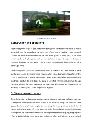
SlideShare a Scribd company logo
1 of 61
A
Summer Training Report
On
NATIONAL THERMAL POWER CORPORATION, BADARPUR
To partial fulfilment of
Bachelors of Electrical Engineering
Session:-2015-16
SubmittedBy:
Alok Kumar Tiwari
EE-4th
Year
1213220007
Submittedto: Head Of Department:
Mr. Siddharth Jain Dr. Sunil Chaudhary
(Seminar Head)
(Department of Electrical Engineering)
Greater Noida Institute of Technology
Plot No-7, K.P.-II, Greater Noida (G. B. Nagar),U.P.
SUBMITTED BY
ALOK KUMAR TIWARI
STUDENT NO:-VT1408
BRANCH:-ELECTRICAL ENGG.
TRAINING
My training starts on 08-JUN-2015 and ended on 18-
JUL-2015 i.e. Six weeks at B.T.P.S. During my training
at B.T.P.S.I was reporting following department for
four weeks training and tried to get as much
knowledge and experience as possible.
EMD(I)-Learnt about coal handling plant, Boiler side
motor & Turbine side motor.
EMD(II)-Learnt about Generator, Transformer, switch
Gear & Switch Yard.
ACKNOWLEDGEMENT
This report is my humble thanks to all officer and
employees of B.T.P.S. Who give their full co-
operation and valuable time during my training and
the course is successfully done.
I would like to thank specially Mr.Man Mohan Singh
and G.D. Sharma & the staff of EMD(I) & EMD(II)
Who have inspired for achieving our goal by giving
their proper guidance during training period.
THE COMPANY….
National Thermal Power Corporation Limited(NTPC)
is the largest power generating company of India. It
was incorporated in the year of 1975 with the
objective of planning, promoting and organising an
integrated development of thermal power in the
country. NTPC is public sector company wholly
owned by Govt. of India. It also achived Maharatna
Status.Today NTPC has power generating capacity in
all the four major power region of country
INSTALLED CAPACITY AROUND THE END OF PERIOD:
13000
28000
66000
112000
212000
2012200019901980197019601950
460017000
50000
100000
150000
200000
250000
1 2 3 4 5 6 7 8 9
YEARS
CAPACITIES
NTPC – a global giant in power sector
Source: www.ntpc.co.in
National Thermal Power Corporation Limited (NTPC) is the largest thermal power
generating company of India. A public sector company incorporated in the year 1975 to
accelerate power development in the country as a wholly owned company of the
Government of India. At present, Government of India holds 89.5% of the total equity
shares of the company and the balance 10.5% is held by FIIs, Domestic Banks, Public and
others.
Based on 1998 data, carried out by Data monitor UK, NTPC is the 6th largest in terms
of thermal power generation and the second most efficient in terms of capacity utilization
amongst the thermal utilities in the world.
NTPC's core business is engineering, construction and operation of power generating
plants and also providing consultancy to power utilities in India and abroad. As on date
the installed capacity of NTPC is 23,749 MW through its 13 coal based (19,480 MW), 7
gas based (3,955 MW) and 3 Joint Venture Projects (314 MW). NTPC acquired 50%
equity of the SAIL Power Supply Corporation Ltd. (SPSCL). This JV Company operates
the captive power plants of Durgapur (120 MW), Rourkela (120 MW) and Bhilai (74
MW). NTPC is also managing Badarpur thermal power station (705 MW) of Government
of India.
NTPC has set new benchmarks for the power industry both in the area of power plant
construction and operations. Its providing power at the cheapest average tariff in the
country..
NTPC is committed to the environment, generating power at minimal environmental
cost and preserving the ecology in the vicinity of the plants. NTPC has undertaken
massive a forestation in the vicinity of its plants. Plantations have increased forest area
and reduced barren land. The massive a forestation by NTPC in and around its
Ramagundam Power station (2600 MW) have contributed reducing the temperature in
the areas by about 3°c. NTPC has also taken proactive steps for ash utilization. In 1991, it
set up Ash Utilization Division
A "Centre for Power Efficiency and Environment Protection (CENPEEP)" has been
established in NTPC with the assistance of United States Agency for International
Development (USAID). Cenpeep is efficiency oriented, eco-friendly and eco-nurturing
initiative - a symbol of NTPC's concern towards environmental protection and continued
commitment to sustainable power development in India.
As a responsible corporate citizen, NTPC is making constant efforts to improve the socio-
economic status of the people affected by its projects. Through its Rehabilitation and
Resettlement programmes, the company endeavors to improve the overall socio
economic status Project Affected Persons.
NTPC was among the first Public Sector Enterprises to enter into a Memorandum of
Understanding (MOU) with the Government in 1987-88. NTPC has been placed under
the 'Excellent category' (the best category) every year since the MOU system became
operative.
Harmony between man and environment is the essence of healthy life and growth.
Therefore, maintenance of ecological balance and a pristine environment has been of
utmost importance to NTPC. It has been taking various measures discussed below for
mitigation of environment pollution due to power generation.
EVOLUTION
NTPC was set up in 1975 in 100% by the ownership of Government
of India. In the last 30 years NTPC has grown into the largest power
utility in India.
In 1997, Government of India granted NTPC status of ‘Navratna’
being one of the nine jewels of India, enhancing the powers to the
Board of directors.
NTPC became a listed company with majority Government
ownership of 89.5%. NTPC becomes third largest by market
capitalisation of listed companies.
The company rechristened as NTPC Limited in line with its
changing business portfolio and transforms itself from a thermal
power utility to an integrated power utility.
National Thermal Power Corporation is the largest power
generation company in India. Forbes Global 2000 for 2008 ranked
it 411th the world.
National Thermal Power Corporation is the largest power
generation company in India. Forbes Global 2000 for 2008 ranked
it 317th in the world.
NTPC has also set up a plan to achieve a target of 50,000 MW
generation capacities.
NTPC has embarked on plans to become a 75,000 MW company by
2017.
1975
1997
2004
2005
2008
2009
2012
2017
NTPC is the largest power utility in India, accounting for about 20% of India’s installed
capacity.
STRATEGIES
Figure 1: NTPC STRATEGIES
NTPC HEADQUARTERS
NTPC Limited is divided in 8 Headquarters
S. NO. HEADQUARTERS CITY
1. NCRHQ DELHI
2. ER HEADQUARTER-1 BHUBANESHWAR
3. ER HEADQUARTER-2 PATNA
4. NRHQ LUCKNOW
5. SR HEADQUARTER HYDERABAD
6. WR-1 HEADQUARTER MUMBAI
7. HYDRO HEADQUARTER DELHI
8. WR-2 HEADQUARTER RAIPUR
NTPC PLANTS
1. Thermal-Coal based
S. NO. CITY STATE INSTALLED
CAPACITY(MW)
1. SINGRAULI UTTAR PRADESH 2000
2. KORBA CHATTISGHAR 2600
3. RAMAGUNDAM ANDHRA PRADESH 2600
4. FARAKKA WEST BENGAL 2100
5. VINDHYACHAL MADHYA PRADESH 3260
6. RIHAND UTTAR PRADESH 2500
7. KAHALGAON BIHAR 2300
8. DADRI UTTAR PRADESH 1820
9. TALCHER ORISSA 3000
10. UNCHAHAR UTTAR PRADESH 1050
11. TALCHER ORISSA 460
12. SIMHADRI ANDHRA PRADESH 1500
13. TANDA UTTAR PRADESH 440
14. BADARPUR DELHI 705
15. SIPAT CHHATTISGHAR 2320
16. SIPAT CHHATTISGHAR 1980
17. BONGAIGAON ASSAM 750
18. MOUDA MAHARASHTRA 1000(2*500MW)
19. RIHAND UTTAR PRADESH 2*500MW
20. BARH BIHAR 3300(5*660)
TOTAL 31495MW
2.COAL BASED (Owned by JVs)
3.GAS Based
S.NO. CITY STATE INSTALLED
CAPACITY(MW)
1. ANTA RAJSTHAN 419
2. AURAIYA UTTAR PRADESH 652
3. KAWAS GUJARAT 645
4. DADRI UTTAR PRADESH 817
5. JHANOR GUJARAT 648
6. KAYAMKULAM KERALA 350
7. FARIDABAD HARYANA 430
TOTAL 3995MW
S NO. NAME OF THE
JV
CITY STATE INSTALLED
CAPACITY(MW)
1. NSPCL DURGAPUR WEST BENGAL 120
2. NSPCL ROURKELA ORISSA 120
3. NSPCL BHILAI CHHATTISGHAR 574
4. NPGC AURANGABAD BIHAR 1980
5. M.T.P.S. KANTI BIHAR 110
6. BRBCL NABINAGAR BIHAR 1000
TOTAL 3904MW
NTPC HYDEL
The company has also stepped up its hydroelectric power (hydel) projects
implementation. Currently the company is mainly interested in the North-east India
wherein the Ministry of Power in India has projected a hydel power feasibility of 3000
MW.
There are few run of the river hydro projects are under construction on tributory of the
Ganges. In which three are being made by NTPC Limited. These are:
Loharinag Pala Hydro Power Project by NTPC Ltd: In Loharinag Pala Hydro Power Project
with a capacity of 600 MW (150 MW x 4 Units). The main package has been awarded.
The present executives' strength is 100+. The project is located on river Bhagirathi (a
tributory of the Ganges) in Uttarkashi district of Uttarakhand state. This is the first
project downstream from the origin of the Ganges at Gangotri(Project has been
discontinued by GoI).
Tapovan Vishnugad 520MW Hydro Power Project by NTPC Ltd: In Joshimath town.#Lata
Tapovan 130MW Hydro Power Project by NTPC Ltd: is further upstream to Joshimath
(under environmental revision) Koldam Hydro Power Project 800 MW in Himachal
Pradesh (130 km from Chandigarh)Amochu in Bhutan Rupasiyabagar Khasiabara HPP,
261 MW in Pithoragarh,uttarakhand State, near China Border.
FUTURE GOALS
The company has also set a serious goal of having 50000 MW of installed capacity by
2012 and 75000 MW by 2017. The company has taken many steps like step-up its
recruitment, reviewing feasibilities of various sites for project implementations etc. and
has been quite successful till date. NTPC will invest about Rs 20,000 crore to set up a
3,900-megawatt (MW) coal-based power project in Madhya Pradesh. Company will also
start coal production from its captive mine in Jharkhand in 2011–12, for which the
company will be investing about 18 billion. ALSTOM would be a part of its 660-MW
supercritical projects for Solapur II and Mouda II in Maharashtra.ALSTOM would execute
turnkey station control and instrumentation (C&I) for this project.
POWER BURDEN
India, as a developing country is characterized by increase in demand for electricity and
as of moment the power plants are able to meet only about 60–75% of this demand on
an yearly average. The only way to meet the requirement completely is to achieve a rate
of power capacity addition (implementing power projects) higher than the rate of
demand addition. NTPC strives to achieve this and undoubtedly leads in sharing this
burden on the country.
ENVIRONMENTPOLICY &ENVIRONMENTMANAGEMENTSYSTEM
Driven by its commitment for sustainable growth of power, NTPC has evolved a well
defined environment management policy and sound environment practices for
minimizing environmental impact arising out of setting up of power plants and
preserving the natural ecology.
NATIONAL ENVIRONMENT POLICY
At the national level, the Ministry of Environment and Forests had prepared a draft
Environment Policy (NEP) and the Ministry of Power along with NTPC actively
participated in the deliberations of the draft NEP. The NEP 2006 has since been
approved by the Union Cabinet in May 2006.
NTPC ENVIRONMENT POLICY
As early as in November 1995, NTPC brought out a comprehensive document entitled
"NTPC Environment Policy and Environment Management System". Amongst the guiding
principles adopted in the document are company's proactive approach to environment,
optimum utilization of equipment, adoption of latest technologies and continual
environment improvement. The policy also envisages efficient utilization of resources,
thereby minimizing waste, maximizing ash utilization and providing green belt all around
the plant for maintaining ecological balance.
ENVIRONMET MANAGEMENT, OCCUPATIONAL HEALTH
and SAFETY SYSTEMS
NTPC has actively gone for adoption of best international practices on environment,
occupational health and safety areas. The organization has pursued the Environmental
Management System (EMS) ISO 14001 and the Occupational Health and Safety
Assessment System OHSAS 18001 at its different establishments. As a result of pursuing
these practices, all NTPC power stations have been certified for ISO 14001 & OHSAS
18001 by reputed national and international Certifying Agencies.
POLLUTION CONTROL SYSTEMS
While deciding the appropriate technology for its projects, NTPC integrates many
environmental provisions into the plant design. In order to ensure that NTPC comply
with all the stipulated environment norms, various state-of-the-art pollution control
systems / devices as discussed below have been installed to control air and water
pollution.
Electrostatic Precipitators
The ash left behind after combustion of coal is arrested in high efficiency Electrostatic
Precipitators (ESP’s) and particulate emission is controlled well within the stipulated
norms. The ash collected in the ESP’s is disposed to Ash Ponds in slurry form.
Flue Gas Stacks
Tall Flue Gas Stacks have been provided for wide dispersion of the gaseous emissions
(SOX, NOX etc) into the atmosphere.
Low-NOX Burners
In gas based NTPC power stations, NOx emissions are controlled by provision of Low-
NOx Burners (dry or wet type) and in coal fired stations, by adopting best combustion
practices.
Neutralization Pits
Neutralization pits have been provided in the Water Treatment Plant (WTP) for pH
correction of the effluents before discharge into Effluent Treatment Plant (ETP) for
further treatment and use.
Coal Settling Pits / Oil Settling Pits
In these Pits, coal dust and oil are removed from the effluents emanating from the Coal
Handling Plant (CHP), coal yard and Fuel Oil Handling areas before discharge into ETP.
DE & DS Systems
Dust Extraction (DE) and Dust Suppression (DS) systems have been installed in all coal
fired power stations in NTPC to contain and extract the fugitive dust released in the Coal
Handling Plant (CHP).
Cooling Towers
Cooling Towers have been provided for cooling the hot Condenser cooling water in
closed cycle Condenser Cooling Water (CCW) Systems. This helps in reduction in thermal
pollution and conservation of fresh water.
Ash Dykes & Ash Disposal systems
Ash ponds have been provided at all coal based stations except Dadri where Dry Ash
Disposal System has been provided. Ash Ponds have been divided into lagoons and
provided with garlanding arrangements for change over of the ash slurry feed points for
even filling of the pond and for effective settlement of the ash particles.
Ash in slurry form is discharged into the lagoons where ash particles get settled from the
slurry and clear effluent water is discharged from the ash pond. The discharged effluents
conform to standards specified by CPCB and the same is regularly monitored.
At its Dadri Power Station, NTPC has set up a unique system for dry ash collection and
disposal facility with Ash Mound formation. This has been envisaged for the first time in
Asia which has resulted in progressive development of green belt besides far less
requirement of land and less water requirement as compared to the wet ash disposal
system.
Ash Water Recycling System
Further, in a number of NTPC stations, as a proactive measure, Ash Water Recycling
System (AWRS) has been provided. In the AWRS, the effluent from ash pond is circulated
back to the station for further ash sluicing to the ash pond. This helps in savings of fresh
water requirements for transportation of ash from the plant.
The ash water recycling system has already been installed and is in operation at
Ramagundam, Simhadri, Rihand, Talcher Kaniha, Talcher Thermal, Kahalgaon, Korba and
Vindhyachal. The scheme has helped stations to save huge quantity of fresh water
required as make-up water for disposal of ash.
Dry Ash Extraction System (DAES)
Dry ash has much higher utilization potential in ash-based products (such as bricks,
aerated autoclaved concrete blocks, concrete, Portland pozzolana cement, etc.). DAES
has been installed at Unchahar, Dadri, Simhadri, Ramagundam, Singrauli, Kahalgaon,
Farakka, Talcher Thermal, Korba, Vindhyachal, Talcher Kaniha and BTPS.
Liquid Waste Treatment Plants & Management System
The objective of industrial liquid effluent treatment plant (ETP) is to discharge lesser and
cleaner effluent from the power plants to meet environmental regulations. After
primary treatment at the source of their generation, the effluents are sent to the ETP for
further treatment. The composite liquid effluent treatment plant has been designed to
treat all liquid effluents which originate within the power station e.g. Water Treatment
Plant (WTP), Condensate Polishing Unit (CPU) effluent, Coal Handling Plant (CHP)
effluent, floor washings, service water drains etc. The scheme involves collection of
various effluents and their appropriate treatment centrally and re-circulation of the
treated effluent for various plant uses.
NTPC has implemented such systems in a number of its power stations such as
Ramagundam, Simhadri, Kayamkulam, Singrauli, Rihand, Vindhyachal, Korba, Jhanor
Gandhar, Faridabad, Farakka, Kahalgaon and Talcher Kaniha. These plants have helped
to control quality and quantity of the effluents discharged from the stations.
Sewage Treatment Plants & Facilities
Sewage Treatment Plants (STPs) sewage treatment facilities have been provided at all
NTPC stations to take care of Sewage Effluent from Plant and township areas. In a
number of NTPC projects modern type STPs with Clarifloculators, Mechanical Agitators,
sludge drying beds, Gas Collection Chambers etc have been provided to improve the
effluent quality. The effluent quality is monitored regularly and treated effluent
conforming to the prescribed limit is discharged from the station. At several stations,
treated effluents of STPs are being used for horticulture purpose.
Environmental Institutional Set-up
Realizing the importance of protection of the environment with speedy development of
the power sector, the company has constituted different groups at project, regional and
Corporate Centre level to carry out specific environment related functions. The
Environment Management Group, Ash Utilisation Group and Centre for Power Efficiency
& Environment Protection (CENPEEP) function from the Corporate Centre and initiate
measures to mitigate the impact of power project implementation on the environment
and preserve ecology in the vicinity of the projects. Environment Management and Ash
Utilisation Groups established at each station, look after various environmental issues of
the individual station.
Environment Reviews
To maintain constant vigil on environmental compliance, Environmental Reviews are
carried out at all operating stations and remedial measures have been taken wherever
necessary. As a feedback and follow-up of these Environmental Reviews, a number of
retrofit and up-gradation measures have been undertaken at different stations.
Such periodic Environmental Reviews and extensive monitoring of the facilities carried
out at all stations have helped in compliance with the environmental norms and timely
renewal of the Air and Water Consents.
UP GRADATION & RETROFITTING of POLLUTION CONTROL SYSTEMS
Waste Management
Various types of wastes such as Municipal or domestic wastes, hazardous wastes, Bio-
Medical wastes get generated in power plant areas, plant hospital and the townships of
projects. The wastes generated are a number of solid and hazardous wastes like used
oils & waste oils, grease, lead acid batteries, other lead bearing wastes (such as garkets
etc.), oil & clarifier sludge, used resin, used photo-chemicals, asbestos packing, e-waste,
metal scrap, C&I wastes, electricial scrap, empty cylinders (refillable), paper, rubber
products, canteen (bio-degradable) wastes, buidling material wastes, silica gel, glass
wool, fused lamps & tubes, fire resistant fluids etc. These wastes fall either under
hazardous wastes category or non-hazardous wastes category as per classification given
in Government of India’s notification on Hazardous Wastes (Management and Handling)
Rules 1989 (as amended on 06.01.2000 & 20.05.2003). Handling and management of
these wastes in NTPC stations have been discussed below.
Advanced / Eco-friendly Technologies
NTPC has gained expertise in operation and management of 200 MW and 500 MW Units
installed at different Stations all over the country and is looking ahead for higher
capacity Unit sizes with super critical steam parameters for higher efficiencies and for
associated environmental gains. At Sipat, higher capacity Units of size of 660 MW and
advanced Steam Generators employing super critical steam parameters have already
been implemented as a green field project.
Higher efficiency Combined Cycle Gas Power Plants are already under operation at all
gas-based power projects in NTPC. Advanced clean coal technologies such as Integrated
Gasification Combined Cycle (IGCC) have higher efficiencies of the order of 45% as
compared to about 38% for conventional plants. NTPC has initiated a techno-economic
study under USDOE / USAID for setting up a commercial scale demonstration power
plant by using IGCC technology. These plants can use low-grade coals and have higher
efficiency as compared to conventional plants.
With the massive expansion of power generation, there is also growing awareness
among all concerned to keep the pollution under control and preserve the health and
quality of the natural environment in the vicinity of the power stations. NTPC is
committed to provide affordable and sustainable power in increasingly larger quantity.
NTPC is conscious of its role in the national endeavour of mitigating energy poverty,
heralding economic prosperity and thereby contributing towards India’s emergence as a
major global economy.
ABOUT BADARPURTHERMAL POWER STATION
Badarpur Thermal Power Station is located at Badarpur area in NCT Delhi. The power
plant is one of the coal based power plants of NTPC. The National Power Training
Institute (NPTI) for North India Region underMinistry of Power, Government of India
was established at Badarpur in 1974, within the BadarpurThermal power plant (BTPS)
complex.
It is situated in south east corner of Delhi on Mathura Road near Faridabad. It was the
first central sector power plant conceived in India, in 1965. It was originally conceived to
provide power to neighbouring states of Haryana, Punjab, Jammu and Kashmir,U.P.,
Rajasthan, and Delhi.But since year 1987 Delhi has become its sole beneficiary.
The coal source include:
1. CCL(Central Coal Fields Ltd.)
2. BCCL(Bharat Coking Coals Ltd.)
3. ECL(Eastern coal Fields Ltd.)
The water supplied is taken from Agra irrigation canal and used for cooling.
BADARPUR THERMAL POWER STATION
COUNTRY INDIA
LOCATION MATHURA ROAD, BADARPUR, NEW DELHI
STATUS ACTIVE
COMISSION DATE 1978
OPERATOR(S) NTPC
POWER STATION INFORMATION
PRIMARY FUEL COAL-FIRED
GENERATION UNITS 5
POWER GENERATION INFORMATION
INSTALLED CAPACITY 705.00 MW
FROM COAL TO ELECTRICITY PROCESS
Coal to Steam
Coal from the coal wagons is unloaded in the coal handling plant. This Coal is
transported up to the raw coal bunkers with the help of belt conveyors. Coal is
transported to Bowl mills by Coal Feeders. The coal is pulverized in the Bowl Mill,
where it is ground to powder form. The mill consists of a round metallic table on
which coal particles fall. This table is rotated with the help of a motor. There are
three large steel rollers, which are spaced 120 apart. When there is no coal, these
rollers do not rotate but when the coal is fed to the table it pack up between roller and
the table and ths forces the rollers to rotate.
FLOW CHART of COAL TO ELECTRICITY
Coal is crushed by the crushing action between the rollers and the rotating table. This
crushed coal is taken away to the furnace through coal pipes with the help of hot and
cold air mixture from P.A. Fan.
P.A. Fan takes atmospheric air, a part of which is sent to Air-Preheaters for heating
while a part goes directly to the mill for temperature control. Atmospheric air from F.D.
Fan is heated in the air heaters and sent to the furnace as combustion air.
Water from the boiler feed pump passes through economizer and reaches the
boiler drum. Water from the drum passes through down comers and goes to the
bottom ring header. Water from the bottom ring header is divided to all the four sides
of the furnace. Due to heat and density difference, the water rises up in the water
wall tubes. Water is partly converted to steam as it rises up in the furnace. This
steam and water mixture is again taken to thee boiler drum where the steam is
separated from water.
Figure 2: TYPICAL DIAGRAM OF COAL BASED THERMAL POWER PLANT
Water follows the same path while the steam is sent to superheaters for
superheating. The superheaters are located inside the furnace and the steam is
superheated (540 oC) and finally it goes to the turbine.
Flue gases from the furnace are extracted by induced draft fan, which maintains
balance draft in the furnace (-5 to –10 mm of wcl) with forced draft fan. These flue
gases emit their heat energy to various super heaters in the pent house and finally
pass through air-preheaters and goes to electrostatic precipitators where the ash
particles are extracted. Electrostatic Precipitator consists of metal plates, which are
electrically charged. Ash particles are attracted on to these plates, so that they do
not pass through the chimney to pollute t he atmosphere. Regular mechanical
hammer blows cause the accumulation of ash to fall to the bottom of the precipitator
where they are collected in a hopper for disposal.
Steam to Mechanical Power
From the boiler, a steam pipe conveys steam to the turbine through a stop valve
(which can be used to shut-off the steam in case of emergency) and through control
valves that automatically regulate the supply of steam to the turbine. Stop valve and
control valves are located in a steam chest and a governor, driven from the main
turbine shaft, operates the control valves to regulate the amount of steam used.
(This depends upon the speed of the turbine and the amount of electricity required
from the generator).
Steam from the control valves enters the high pressure cylinder of the turbine, where it
passes through a ring of stationary blades fixed to the cylinder wall. These act as
nozzles and direct the steam into a second ring of moving blades mounted on a disc
secured to the turbine shaft. The second ring turns the shafts as a result of the force of
steam. The stationary and moving blades together constitute a „stage‟ of turbine and
in practice many stages are necessary, so that the cylinder contains a number of rings
of stationary blades with rings of moving blades arranged between them. The steam
passes through each stage in turn until it reaches the end of the high-pressure
cylinder and in its passage some of its heat energy is changed into mechanical energy.
The steam leaving the high pressure cylinder goes back to the boiler for reheating and
returns by a further pipe to the intermediate pressure cylinder. Here it passes through
another series of stationary and moving blades.
Finally, the steam is taken to the low-pressure cylinders, each of which enters at the
centre flowing outwards in opposite directions through the rows of turbine blades
through an arrangement called the „double flow‟- to the extremities of the cylinder.
As the steam gives up its heat energy to drive the turbine, its temperature and
pressure fall and it expands. Because of this expansion the blades are much larger
and longer towards the low pressure ends of the turbine.
Mechanical Power to Electrical Power
As the blades of turbine rotate, the shaft of the generator, which is coupled to tha
of t he turbine, also rotates. It results in rotation of the coil of the generator, which
causes induced electricity to be produced.
Basic Power Plant Cycle
COMPONENTSOF A COAL FIRED THERMAL PLANT
The thermal (steam) power plant uses a dual (vapour+ liquid) phase cycle. It is a close
cycle to enable the working fluid (water) to be used again and again. The cycle used
is Rankine Cycle modified to include superheating of steam, regenerative feed water
heating and reheating of steam. On large turbines, it becomes economical to increase
the cycle efficiency by using reheat, which is a way of partially overcoming
temperature limitations. By returning partially expanded steam, to a reheat, the
average temperature at which the heat is added, is increased and, by expanding this
reheated steam to the remaining stages of the turbine, the exhaust wetness is
considerably less than it would otherwise be conversely, if the maximum tolerable
wetness is allowed, the initial pressure of the steam can be appreciably increased.
Bleed Steam Extraction: For regenerative system, nos. of non-regulated extractions is
taken from HP, IP turbine. Regenerative heating of the boiler feed water is widely
used in modern power plants; the effect being to increase the average temperature
at which heat is added to the cycle, thus improving the cycle efficiency.
On large turbines, it becomes economical to increase the cycle efficiency by using
reheat, which is a way of partially overcoming temperature limitations. By returning
partially expanded steam, to a reheat, the average temperature at which the heat is
added, is increased and, by expanding this reheated steam to the remaining stages of
the turbine, the exhaust wetness is considerably less than it would otherwise be
conversely, if the maximum tolerable wetness is allowed, the initial pressure of the steam
can be appreciably increased.
Bleed Steam Extraction: For regenerative system, nos. of non-regulated extractions is
taken from HP, IP turbine. Regenerative heating of the boiler feed water is widely used
in modern power plants; the effect being to increase the average temperature at which
heat is added to the cycle, thus improving the cycle efficiency.
INTSALLED CAPACITY OF NTPC, BADARPUR
MAIN GENERATOR
Maximum continuous KVA rating 24700KVA
Maximum continuous KW 210000KW
Rated terminal voltage 15750V
Rated Stator current 9050 A
Rated Power Factor 0.85 lag
Excitation current at MCR Condition 2600 A
Slip-ring Voltage at MCR Condition 310 V
Rated Speed 3000 rpm
Rated Frequency 50 Hz
Short circuit ratio 0.49
Efficiency at MCR Condition 98.4%
Direction of rotation viewed Anti Clockwise
Phase Connection Double Star
Number of terminals brought out 9(6 neutral and 3 phases)
MAIN TURBINE DATA
Rated output of Turbine 210 MW
Rated speed of turbine 3000 rpm
Rated pressure of steam before emergency 130 kg/cm^2
Stop valve rated live steam temperature 535 o Celsius
Rated steam temperature after reheat at inlet to receptor valve 535 o Celsius
Steam flow at valve wide open condition 670 tons/hour
Rated quantity of circulating water through condenser 27000 cm/hour
1. For cooling water temperature (o Celsius) 24,27,30,33
2. Steam flow required for 210 MW in ton/hour 68,645,652,662
3. Rated pressure at exhaust of LP turbine in mm of Hg 19.9,55.5,65.4,67.7
OPERATION
THERMAL POWER PLANT
A Thermal Power Station comprises all of the equipment and a subsystem required to
produce electricity by using a steam generating boiler fired with fossil fuels or befouls to
drive an electrical generator. Some prefer to use the term ENERGY CENTER because such
facilities convert forms of energy, like nuclear energy, gravitational potential energy or heat
energy (derived from the combustion of fuel) into electrical energy. However, POWER
PLANT is the most common term in the united state; While POWER STATION prevails in
many Commonwealth countries and especially in the United Kingdom.
Such power stations are most usually constructed on a very large scale and designed for
continuous operation.
Typical elements of a coal fired thermal power station
1. Cooling water pump
2. Three -phase transmission line
3. Step up transformer
4. Electrical Generator
5. Low pressure steam
6. Boiler feed water pump
7. Surface condenser
8. Intermediate pressure steam turbine
9. Steam control valve
10. High pressure steam turbine
11. Deaerator Feed water heater
12. Coal conveyor
13. Coal hopper
14. Coal pulverizer
15. Boiler steam drum
16. Bottom ash hoper
17. Super heater
18. Forced draught (draft) fan
19. Reheater
20. Combustion air intake
21. Economizer
22. Air preheater
23. Precipitator
24. Induced draught (draft) fan
25. Fuel gas stack
The description of some of the components written above is described as follows:
1. Cooling towers
Cooling Towers are evaporative coolers used for cooling water or other working medium to
near the ambivalent web-bulb air temperature. Cooling towers use evaporation of water to
reject heat from processes such as cooling the circulating water used in oil refineries,
Chemical plants, power plants and building cooling, for example. The tower vary in size from
small roof-top units to very large hyperboloid structures that can be up to 200 meters tall
and 100 meters in diameter, or rectangular structure that can be over 40 meters tall and 80
meters long. Smaller towers are normally factory built, while larger ones are constructed on
site.
The primary use of large, industrial cooling tower system is to remove the heat absorbed in
the circulating cooling water systems used in power plants, petroleum refineries,
petrochemical and chemical plants, natural gas processing plants and other industrial
facilities. The absorbed heat is rejected to the atmosphere by the evaporation of some of
the cooling water in mechanical forced-draft or induced draft towers or in natural draft
hyperbolic shaped cooling towers as seen at most nuclear power plants.
2. Three phase transmission line
Three phase electric power is a common method of electric power transmission. It is a type
of polyphase system mainly used to power motors and many other devices. A Three phase
system uses less conductor material to transmit electric power than equivalent single phase,
two phase, or direct current system at the same voltage. In a three phase system, three
circuits reach their instantaneous peak values at different times. Taking one conductor as
the reference, the other two current are delayed in time by one-third and two-third of one
cycle of the electrical current. This delay between “phases” has the effect of giving constant
power transfer over each cycle of the current and also makes it possible to produce a
rotating magnetic field in an electric motor.
At the power station, an electric generator converts mechanical power into a set of electric
currents, one from each electromagnetic coil or winding of the generator. The current are
sinusoidal functions of time, all at the same frequency but offset in time to give different
phases. In a three phase system the phases are spaced equally, giving a phase separation of
one-third one cycle. Generators output at a voltage that ranges from hundreds of volts to
30,000 volts. At the power station, transformers: step-up” this voltage to one more suitable
for transmission.
After numerous further conversions in the transmission and distribution network the power
is finally transformed to the standard mains voltage (i.e. the “household” voltage).
The power may already have been split into single phase at this point or it may still be three
phase. Where the step-down is 3 phase, the output of this transformer is usually star
connected with the standard mains voltage being the phase-neutral voltage. Another
system commonly seen in North America is to have a delta connected secondary with a
center tap on one of the windings supplying the ground and neutral. This allows for 240 V
three phase as well as three different single phase voltages( 120 V between two of the
phases and neutral , 208 V between the third phase ( known as a wild leg) and neutral and
240 V between any two phase) to be available from the same supply.
3. Electrical generator
An Electrical generator is a device that converts kinetic energy to electrical energy, generally
using electromagnetic induction. The task of converting the electrical energy into
mechanical energy is accomplished by using a motor. The source of mechanical energy may
be a reciprocating or turbine steam engine, , water falling through the turbine are made in a
variety of sizes ranging from small 1 hp (0.75 kW) units (rare) used as mechanical drives for
pumps, compressors and other shaft driven equipment , to 2,000,000 hp(1,500,000 kW)
turbines used to generate electricity. There are several classifications for modern steam
turbines.
Steam turbines are used in all of our major coal fired power stations to drive the generators
or alternators, which produce electricity. The turbines themselves are driven by steam
generated in ‘Boilers’ or ‘steam generators’ as they are sometimes called.
Electrical power stations use large steam turbines driving electric generators to produce
most (about 86%) of the world’s electricity. These centralized stations are of two types:
fossil fuel power plants and nuclear power plants. The turbines used for electric power
generation are most often directly coupled to their-generators .As the generators must
rotate at constant synchronous speeds according to the frequency of the electric power
system, the most common speeds are 3000 r/min for 50 Hz systems, and 3600 r/min for 60
Hz systems. Most large nuclear sets rotate at half those speeds, and have a 4-pole generator
rather than the more common 2-pole one.
Energy in the steam after it leaves the boiler is converted into rotational energy as it passes
through the turbine. The turbine normally consists of several stage with each stages
consisting of a stationary blade (or nozzle) and a rotating blade. Stationary blades convert
the potential energy of the steam into kinetic energy into forces, caused by pressure drop,
which results in the rotation of the turbine shaft. The turbine shaft is connected to a
generator, which produces the electrical energy.
4. Boiler feed water pump
A Boiler feed water pump is a specific type of pump used to pump water into a steam boiler.
The water may be freshly supplied or retuning condensation of the steam produced by the
boiler. These pumps are normally high pressure units that use suction from a condensate
return system and can be of the centrifugal pump type or positive displacement type.
EXTERNAL VIEW OF BOILER
Construction and operation:
Feed water pumps range in size up to many horsepower and the electric motor is usually
separated from the pump body by some form of mechanical coupling. Large industrial
condensate pumps may also serve as the feed water pump. In either case, to force the
water into the boiler; the pump must generate sufficient pressure to overcome the steam
pressure developed by the boiler. This is usually accomplished through the use of a
centrifugal pump.
Feed water pumps usually run intermittently and are controlled by a float switch or other
similar level-sensing device energizing the pump when it detects a lowered liquid level in the
boiler is substantially increased. Some pumps contain a two-stage switch. As liquid lowers to
the trigger point of the first stage, the pump is activated. I f the liquid continues to drop
(perhaps because the pump has failed, its supply has been cut off or exhausted, or its
discharge is blocked); the second stage will be triggered.
5. Steam-powered pumps
Steam locomotives and the steam engines used on ships and stationary applications such as
power plants also required feed water pumps. In this situation, though, the pump was often
powered using a small steam engine that ran using the steam produced by the boiler. A
means had to be provided, of course, to put the initial charge of water into the boiler(before
steam power was available to operate the steam-powered feed water pump).the pump was
often a positive displacement pump that had steam valves and cylinders at one end and
feed water cylinders at the other end; no crankshaft was required.In thermal plants, the
primary purpose of surface condenser is to condense the exhaust steam from a steam
turbine to obtain maximum efficiency and also to convert the turbine exhaust steam into
pure water so that it may be reused in the steam generator or boiler as boiler feed water. By
condensing the exhaust steam of a turbine at a pressure below atmospheric pressure, the
steam pressure drop between the inlet and exhaust of the turbine is increased, which
increases the amount heat available for conversion to mechanical power. Most of the heat
liberated due to condensation of the exhaust steam is carried away by the cooling medium
(water or air) used by the surface condenser.
6. Control valves
Control valves are valves used within industrial plants and elsewhere to control operating
conditions such as temperature, pressure, flow, and liquid Level by fully partially opening or
closing in response to signals received from controllers that compares a “set point” to a
“process variable” whose value is provided by sensors that monitor changes in such
conditions. The opening or closing of control valves is done by means of electrical, hydraulic
or pneumatic systems
7. Deaerator
A Dearator is a device for air removal and used to remove dissolved gases (an alternate
would be the use of water treatment chemicals) from boiler feed water to make it non-
corrosive. A dearator typically includes a vertical domed deaeration section as the
deaeration boiler feed water tank. A Steam generating boiler requires that the circulating
steam, condensate, and feed water should be devoid of dissolved gases, particularly
corrosive ones and dissolved or suspended solids. The gases will give rise to corrosion of the
metal. The solids will deposit on the heating surfaces giving rise to localized heating and
tube ruptures due to overheating. Under some conditions it may give to stress corrosion
cracking.
Deaerator level and pressure must be controlled by adjusting control valves- the level by
regulating condensate flow and the pressure by regulating steam flow. If operated properly,
most deaerator vendors will guarantee that oxygen in the deaerated water will not exceed 7
ppb by weight (0.005 cm3/L)
8. Feed water heater
A Feed water heater is a power plant component used to pre-heat water delivered to a
steam generating boiler. Preheating the feed water reduces the irreversible involved in
steam generation and therefore improves the thermodynamic efficiency of the system. This
reduces plant operating costs and also helps to avoid thermal shock to the boiler metal
when the feed water is introduces back into the steam cycle.
In a steam power (usually modeled as a modified Ranking cycle), feed water heaters allow
the feed water to be brought up to the saturation temperature very gradually. This
minimizes the inevitable irreversibility’s associated with heat transfer to the working fluid
(water). A belt conveyor consists of two pulleys, with a continuous loop of material- the
conveyor Belt – that rotates about them. The pulleys are powered, moving the belt and the
material on the belt forward. Conveyor belts are extensively used to transport industrial and
agricultural material, such as grain, coal, ores etc.
9. Pulverizer
A pulverizer is a device for grinding coal for combustion in a furnace in a fossil fuel power
plant.
10. Boiler Steam Drum
Steam Drums are a regular feature of water tube boilers. It is reservoir of water/steam at
the top end of the water tubes in the water-tube boiler. They store the steam generated in
the water tubes and act as a phase separator for the steam/water mixture. The difference in
densities between hot and cold water helps in the accumulation of the “hotter”-water/and
saturated –steam into steam drum. Made from high-grade steel (probably stainless) and its
working involves temperatures 390’C and pressure well above 350psi (2.4MPa). The
separated steam is drawn out from the top section of the drum. Saturated steam is drawn
off the top of the drum. The steam will re-enter the furnace in through a super heater, while
the saturated water at the bottom of steam drum flows down to the mud-drum /feed water
drum by down comer tubes accessories include a safety valve, water level indicator and fuse
plug. A steam drum is used in the company of a mud-drum/feed water drum which is
located at a lower level. So that it acts as a sump for the sludge or sediments which have a
tendency to the bottom.
11. Super Heater
A Super heater is a device in a steam engine that heats the steam generated by the boiler
again increasing its thermal energy and decreasing the likelihood that it will condense inside
the engine. Super heaters increase the efficiency of the steam engine, and were widely
adopted. Steam which has been superheated is logically known as superheated steam; non-
superheated steam is called saturated steam or wet steam; Super heaters were applied to
steam locomotives in quantity from the early 20th century, to most steam vehicles, and so
stationary steam engines including power stations.
12. Economizers
Economizer, or in the UK economizer, are mechanical devices intended to reduce energy
consumption, or to perform another useful function like preheating a fluid. The term
economizer is used for other purposes as well.Boiler, power plant, and heating, ventilating
and air conditioning. In boilers, economizer are heat exchange devices that heat fluids ,
usually water, up to but not normally beyond the boiling point of the fluid. Economizers are
so named because they can make use of the enthalpy and improving the boiler’s efficiency.
They are a device fitted to a boiler which saves energy by using the exhaust gases from the
boiler to preheat the cold water used the fill it (the feed water). Modern day boilers, such as
those in cold fired power stations, are still fitted with economizer which is decedents of
Green’s original design. In this context they are turbines before it is pumped to the boilers.
A common application of economizer is steam power plants is to capture the waste hit from
boiler stack gases (flue gas) and transfer thus it to the boiler feed water thus lowering the
needed energy input , in turn reducing the firing rates to accomplish the rated boiler output
. Economizer lower stack temperatures which may cause condensation of acidic combustion
gases and serious equipment corrosion damage if care is not taken in their design and
material selection.
13. Air Preheater
Air preheater is a general term to describe any device designed to heat air before another
process (for example, combustion in a boiler). The purpose of the air preheater is to recover
the heat from the boiler flue gas which increases the thermal efficiency of the boiler by
reducing the useful heat lost in the fuel gas. As a consequence, the flue gases are also sent
to the flue gas stack (or chimney) at a lower temperature allowing simplified design of the
ducting and the flue gas stack. It also allows control over the temperature of gases leaving
the stack.
14. Precipitator
An Electrostatic precipitator (ESP) or electrostatic air cleaner is a particulate device that
removes particles from a flowing gas (such As air) using the force of an induced electrostatic
charge. Electrostatic precipitators are highly efficient filtration devices, and can easily
remove fine particulate matter such as dust and smoke from the air steam.
ESP’s continue to be excellent devices for control of many industrial particulate emissions,
including smoke from electricity-generating utilities (coal and oil fired), salt cake collection
from black liquor boilers in pump mills, and catalyst collection from fluidized bed catalytic
crackers from several hundred thousand ACFM in the largest coal-fired boiler application.
The original parallel plate-Weighted wire design (described above) has evolved as more
efficient ( and robust) discharge electrode designs were developed, today focusing on rigid
discharge electrodes to which many sharpened spikes are attached , maximizing corona
production. Transformer –rectifier systems apply voltages of 50-100 Kilovolts at relatively
high current densities. Modern controls minimize sparking and prevent arcing, avoiding
damage to the components. Automatic rapping systems and hopper evacuation systems
remove the collected particulate matter while on line allowing ESP’s to stay in operation for
years at a time.
15. Fuel gas stack
A Fuel gas stack is a type of chimney, a vertical pipe, channel or similar structure through
which combustion product gases called fuel gases are exhausted to the outside air. Fuel
gases are produced when coal, oil, natural gas, wood or any other large combustion device.
Fuel gas is usually composed of carbon dioxide (CO2) and water vapor as well as nitrogen
and excess oxygen remaining from the intake combustion air. It also contains a small
percentage of pollutants such as particulates matter, carbon mono oxide, nitrogen oxides
and sulfur oxides. The flue gas stacks are often quite tall, up to 400 meters (1300 feet) or
more, so as to disperse the exhaust pollutants over a greater aria and thereby reduce the
concentration of the pollutants to the levels required by governmental environmental
policies and regulations.
When the fuel gases exhausted from stoves, ovens, fireplaces or other small sources within
residential abodes, restaurants , hotels or other stacks are referred to as chimneys.
EMD- I
Electrical Maintenance Division I
It is responsible for the maintenance of:
HT/LT MOTORS TURBINE& BOILER SIDE
Boiler Side Motors:
For 1, units 1, 2, 3
1. ID Fans 2 in no.
2. FD Fans 2 in no.
3. PA Fans 2 in no.
4. Mill Fans 3 in no.
5. Ball mill fans 3 in no.
6. RC feeders 3 in no.
7. Slag Crushers 5 in no.
8. DM Make up Pump 2 in no.
9. PC Feeders 4 in no.
10. Worm Conveyor 1 in no.
11. Furnikets 4 in no.
For stage units 1, 2, 3
1. I.D Fans 2 in no.
2. F.D Fans 2 in no.
3. P.A Fans 2 in no.
4. Bowl Mills 6 in no.
5. R.C Feeders 6 in no.
6. Clinker Grinder 2 in no.
7. Scrapper 2 in no.
8. Seal Air Fans 2 in no.
9. Hydrazine & Phosphorous Dozing 2 in no.
Figure 3: EXTERNAL VIEW OF ID, PA & FD FANS
COAL HANDLING PLANT(C.H.P) &NEW COAL HANDLING PLANT(N.C.H.P)
The old coal handling plant caters to the need of units 2,3,4,5 and 1 whereas the latter
supplies coal to units 4 and V.O.C.H.P. supplies coal to second and third stages in the advent
coal to usable form to (crushed) form its raw form and send it to bunkers, from where it is
send to furnace.
FLOW CHART OF COAL HANDLING PLANT
Major Components
1. Wagon Tippler: - Wagons from the coal yard come to the tippler and are emptied
here. The process is performed by a slip –ring motor of rating: 55 KW, 415V, 1480 RPM. This
motor turns the wagon by 135 degrees and coal falls directly on the conveyor through
vibrators. Tippler has raised lower system which enables is to switch off motor when
required till is wagon back to its original position. It is titled by weight balancing principle.
The motor lowers the hanging balancing weights, which in turn tilts the conveyor. Estimate
of the weight of the conveyor is made through hydraulic weighing machine.
2. Conveyor: - There are 14 conveyors in the plant. They are numbered so that their
function can be easily demarcated. Conveyors are made of rubber and more with a speed of
250-300m/min. Motors employed for conveyors has a capacity of 150 HP. Conveyors have a
capacity of carrying coal at the rate of 400 tons per hour. Few conveyors are double belt,
this is done for imp. Conveyors so that if a belt develops any problem the process is not
stalled. The conveyor belt has a switch after every 25-30 m on both sides so stop the belt in
case of emergency. The conveyors are 1m wide, 3 cm thick and made of chemically treated
vulcanized rubber. The max angular elevation of conveyor is designed such as never to
exceed half of the angle of response and comes out to be around 20 degrees.
3. Zero Speed Switch:-It is safety device for motors, i.e., if belt is not moving and the
motor is on the motor may burn. So to protect this switch checks the speed of the belt and
switches off the motor when speed is zero.
4. Metal Separators: - As the belt takes coal to the crusher, No metal pieces should
go along with coal. To achieve this objective, we use metal separators. When coal is
dropped to the crusher hoots, the separator drops metal pieces ahead of coal. It has a
magnet and a belt and the belt is moving, the pieces are thrown away. The capacity of this
device is around 50 kg. .The CHP is supposed to transfer 600 tons of coal/hr, but practically
only 300-400 tons coal is transfer
5. Crusher: - Both the plants use TATA crushers powered by BHEL. Motors. The crusher
is of ring type and motor ratings are 400 HP, 606 KV. Crusher is designed to crush the pieces
to 20 mm size i.e. practically considered as the optimum size of transfer via conveyor.
6. Rotatory Breaker: - OCHP employs mesh type of filters and allows particles of
20mm size to go directly to RC bunker, larger particles are sent to crushes. This leads to
frequent clogging. NCHP uses a technique that crushes the larger of harder substance like
metal impurities easing the load on the magnetic separators.
3. MILLING SYSTEM
1. RC Bunker: - Raw coal is fed directly to these bunkers. These are 3 in no. per boiler. 4
& ½ tons of coal are fed in 1 hr. the depth of bunkers is 10m.
2. RC Feeder: - It transports pre crust coal from raw coal bunker to mill. The quantity of
raw coal fed in mill can be controlled by speed control of aviator drive controlling damper
and aviator change.
3. Ball Mill: - The ball mill crushes the raw coal to a certain height and then allows it to
fall down. Due to impact of ball on coal and attraction as per the particles move over each
other as well as over the Armor lines, the coal gets crushed. Large particles are broken by
impact and full grinding is done by attraction. The Drying and grinding option takes place
simultaneously inside the mill.
4. Classifier: - It is equipment which serves separation of fine pulverized coal particles
medium from coarse medium. The pulverized coal along with the carrying medium strikes
the impact plate through the lower part. Large particles are then transferred to the ball mill.
5. Cyclone Separators: - It separates the pulverized coal from carrying medium. The
mixture of pulverized coal vapour caters the cyclone separators.
6. The Tturniket: - It serves to transport pulverized coal from cyclone separators to
pulverized coal bunker or to worm conveyors. There are 4 turnikets per boiler.
7. Worm Conveyor: - It is equipment used to distribute the pulverized coal from
bunker of one system to bunker of other system. It can be operated in both directions.
8. Mills Fans: - It is of 3 types:
Six in all and are running condition all the time.
(a) ID Fans: - Located between electrostatic precipitator and chimney.
Type-radical
Speed-1490 rpm
Rating-300 KW
Voltage-6.6 KV
Lubrication-by oil
(b) FD Fans: - Designed to handle secondary air for boiler. 2 in number and provide
ignition of coal.
Type-axial
Speed-990 rpm
Rating-440 KW
Voltage-6.6 KV
(c)Primary Air Fans: - Designed for handling the atmospheric air up to 50 degrees
Celsius, 2 in number
And they transfer the powered coal to burners to firing.
Type-Double suction radial
Rating-300 KW
Voltage-6.6 KV
Lubrication-by oil
Type of operation-continuous
9. Bowl Mill: - One of the most advanced designs of coal pulverizes presently
manufactured.
Motor Specification
Squirrel cage induction motor
Rating-340 KW
Voltage-6600KV
Curreen-41.7A
Speed-980 rpm
Frequency-50 Hz
No-load current-15-16 A
4. NEW COAL HANDLING PLANT
1. Wagon Tippler:
Motor Specification
(i) H.P 75 HP
(ii) Voltage 415, 3 phase
(iii) Speed 1480 rpm
(iv) Frequency 50 Hz
(v) Current rating 102 A
2. Coal feed to plant:
Feeder motor specification
(i) Horse power 15 HP
(ii) Voltage 415V, 3 phase
(iii) Speed 1480 rpm
(iv) Frequency 50 Hz
3. Conveyors:-
10A, 10B 11A, 11B 12A, 12B 13A, 13B 14A, 14B 15A, 15B
16A, 16B 17A, 17B 18A, 18B
4. Transfer Point 6
5. Breaker House
6. Rejection House
7. Reclaim House
8. Transfer Point 7
9. Crusher House
The coal arrives in wagons via railways and is tippled by the wagon tipplers into the hoppers.
If coal is oversized (>400 mm sq) then it is broken manually so that it passes the hopper
mesh. From the hopper mesh it is taken to the transfer point TP6 by conveyor 12A ,12B
which takes the coal to the breaker house , which renders the coal size to be 100mm sq. the
stones which are not able to pass through the 100mm sq of hammer are rejected via
conveyors 18A,18B to the rejection house . Extra coal is to sent to the reclaim hopper via
conveyor 16. From breaker house coal is taken to the TP7 via Conveyor 13A, 13B. Conveyor
17A, 17B also supplies coal from reclaim hopper, From TP7 coal is taken by conveyors 14A,
14B to crusher house whose function is to render the size of coal to 20mm sq. now the
conveyor labors are present whose function is to recognize and remove any stones moving
in the conveyors . In crusher before it enters the crusher. After being crushed, if any metal is
still present it is taken care of by metal detectors employed in conveyor 10.
10. SWITCH GEAR
It makes or breaks an electrical circuit.
1. Isolation: - A device which breaks an electrical circuit when circuit is switched on to no
load. Isolation is normally used in various ways for purpose of isolating a certain portion
when required for maintenance.
2. Switching Isolation: - It is capable of doing things like interrupting transformer
magnetized current, interrupting line charging current and even perform load transfer
switching. The main application of switching isolation is in connection with transformer
feeders as unit makes it possible to switch out one transformer while other is still on load.
3. Circuit Breakers: - One which can make or break the circuit on load and even on faults is
referred to as circuit breakers. This equipment is the most important and is heavy duty
equipment mainly utilized for protection of various circuits and operations on load.
Normally circuit breakers installed are accompanied by isolators
4. Load Break Switches: - These are those interrupting devices which can make or break
circuits. These are normally on same circuit, which are backed by circuit breakers.
5. Earth Switches: - Devices which are used normally to earth a particular system, to avoid
any accident happening due to induction on account of live adjoining circuits. These
equipments do not handle any appreciable current at all. Apart from this equipment there
are a number of relays etc. which are used in switchgear.
LT Switchgear
It is classified in following ways:-
1. Main Switch: - Main switch is control equipment which controls or disconnects the main
supply. The main switch for 3 phase supply is available for tha range 32A, 63A, 100A, 200Q,
300A at 500V grade.
2. Fuses: - With Avery high generating capacity of the modern power stations extremely
heavy carnets would flow in the fault and the fuse clearing the fault would be required to
withstand extremely heavy stress in process.
It is used for supplying power to auxiliaries with backup fuse protection, rotary switch up to
25A. With fuses, quick break, quick make and double break switch fuses for 63A and 100A,
switch fuses for 200A, 400A, 600A, 800A and 1000A are used.
3. Contractors: - AC Contractors are 3 poles suitable for D.O.L Starting of motors and
protecting the connected motors.
4. Overload Relay: - For overload protection, thermal over relay are best suited for this
purpose. They operate due to the action of heat generated by passage of current through
relay element.
5. Air Circuit Breakers: - It is seen that use of oil in circuit breaker may cause a fire. So in all
circuits breakers at large capacity air at high pressure is used which is maximum at the time
of quick tripping of contacts. This reduces the possibility of sparking. The pressure may vary
from 50-60 kg/cm^2 for high and medium capacity circuit breakers.
HT Switch Gear
1. Minimum oil Circuit Breaker: - These use oil as quenching medium. It comprises of simple
dead tank row pursuing projection from it. The moving contracts are carried on an iron arm
lifted by a long insulating tension rod and are closed simultaneously pneumatic operating
mechanism by means of tensions but throw off spring to be provided at mouth of the
control the main current within the controlled device.
Type-HKH 12/1000c
· Rated Voltage-66 KV
· Normal Current-1250A
· Frequency-5Hz
· Breaking Capacity-3.4+KA Symmetrical
· 3.4+KA Asymmetrical
· 360 MVA Symmetrical
· Operating Coils-CC 220 V/DC
§ FC 220V/DC
· Motor Voltage-220 V/DC
2. Air Circuit Breaker: - In this the compressed air pressure around 15 kg per cm^2 is used
for extinction of arc caused by flow of air around the moving circuit . The breaker is closed
by applying pressure at lower opening and opened by applying pressure at upper opening.
When contacts operate, the cold air rushes around the movable contacts and blown the arc.
It has the following advantages over OCB:-
i. Fire hazard due to oil are eliminated.
ii. Operation takes place quickly.
iii. There are less burning contacts since the duration is short and consistent.
iv. Facility for frequent operation since the cooling medium is replaced constantly.
Rated Voltage-6.6 KV
Current-630 A
Auxiliary current-220 V/DC
3. SF6 Circuit Breaker: - This type of circuit breaker is of construction to dead tank bulk oil to
circuit breaker but the principle of current interruption is similar o that of air blast circuit
breaker. It simply employs the arc extinguishing medium namely SF6 the performance of
gas. When it is broken down under an electrical stress, it will quickly reconstitute itself
· Circuit Breakers-HPA
· Standard-1 EC 56
· Rated Voltage-12 KV
· Insulation Level-28/75 KV
· Rated Frequency-50 Hz
· Breaking Current-40 KA
· Rated Current-1600 A
· Making Capacity-110 KA
· Rated Short Time Current 1/3s -40 A
· Mass Approximation-185 KG
· Auxiliary Voltage
. Closing Coil-220 V/DC
. Opening Coil-220 V/DC
· Motor-220 V/DC
· SF6 Pressure at 20 Degree Celsius-0.25 KG
· SF6 Gas Per pole-0.25 KG
4. Vacuum Circuit Breaker: - It works on the principle that vacuum is used to save the
purpose of insulation and it implies that pr of gas at which breakdown voltage is
independent of pressure. It regards of insulation and strength, vacuum is superior dielectric
medium and is better that all other medium except air and sulphur which are generally used
at high pressure.
· Rated frequency-50 Hz
· Rated making Current-10 Peak KA
· Rated Voltage-12 KV
· Supply Voltage Closing-220 V/DC
· Rated Current-1250 A
· Supply Voltage Tripping-220 V/DC
· Insulation Level-IMP 75 KVP
· Rated Short Time Current-40 KA (3 SEC), Weight of Breaker-8 KG
EMD II
Electrical Maintenance division II
This division is divided as follows
Generator andAuxiliaries
Generator Fundamentals
The transformation of mechanical energy into electrical energy is carried out by the
Generator. This Chapter seeks to provide basic understanding about the working principles
and development of Generator.
Figure 4: CROSS-SECTIONAL VIEW OF A GENERATOR
Working Principle
The A.C. Generator or alternator is based upon the principle of electromagnetic induction
and consists generally of a stationary part called stator and a rotating part called rotor. The
stator housed the armature windings. The rotor houses the field windings. D.C. voltage is
applied to the field windings through slip rings. When the rotor is rotated, the lines of
magnetic flux (i.e. magnetic field) cut through the stator windings. This induces an
electromagnetic force (EMF) in the stator windings. The magnitude of this EMF is given by
the following expression.
E = 4.44 /O FN volts
0 = Strength of magnetic field in Weber’s.
F = Frequency in cycles per second or Hertz.
N = Number of turns in a coil of stator winding
F = Frequency = P*n/120
Where P = Number of poles
n = revolutions per second of rotor.
From the expression it is clear that for the same frequency, number of poles increases with
decrease in speed and vice versa. Therefore, low speed hydro turbine drives generators
have 14 to 20 poles were as high speed steam turbine driven generators have generally 2
poles.
Generator component
This deals with the two main components of the Generator viz. Rotor, its winding &
balancing and stator, its frame, core & windings.
Rotor
The electrical rotor is the most difficult part of the generator to design. It revolves in most
modern generators at a speed of 3,000 revolutions per minute. The problem of
guaranteeing the dynamic strength and operating stability of such a rotor is complicated by
the fact that a massive non-uniform shaft subjected to a multiplicity of differential stresses
must operate in oil lubricated sleeve bearings supported by a structure mounted on
foundations all of which possess complex dynamic be behavior peculiar to them. It is also an
electromagnet and to give it the necessary magnetic strength
The windings must carry a fairly high current. The passage of the current through the
windings generates heat but the temperature must not be allowed to become so high,
otherwise difficulties will be experienced with insulation. To keep the temperature down,
the cross section of the conductor could not be increased but this would introduce another
problems. In order to make room for the large conductors, body and this would cause
mechanical weakness. The problem is really to get the maximum amount of copper into the
windings without reducing the mechanical strength. With good design and great care in
construction this can be achieved. The rotor is a cast steel ingot, and it is further forged and
machined. Very often a hole is bored through the centre of the rotor axially from one end of
the other for inspection. Slots are then machined for windings and ventilation.
Rotor winding
Silver bearing copper is used for the winding with mica as the insulation between
conductors. A mechanically strong insulator such as micanite is used for lining the slots.
Later designs of windings for large rotor incorporate combination of hollow conductors with
slots or holes arranged to provide for circulation of the cooling gas through the actual
conductors. When rotating at high speed. Centrifugal force tries to lift the windings out of
the slots and they are contained by wedges. The end rings are secured to a turned recess in
the rotor body, by shrinking or screwing and supported at the other end by fittings carried
by the rotor body. The two ends of windings are connected to slip rings, usually made of
forged steel, and mounted on insulated sleeves.
Rotor balancing
When completed the rotor must be tested for mechanical balance, which means that a
check is made to see if it will run up to normal speed without vibration. To do this it would
have to be uniform about its central axis and it is most unlikely that this will be so to the
degree necessary for perfect balance. Arrangements are therefore made in all designs to fix
adjustable balance weights around the circumference at each end.
Stator
Stator frame: The stator is the heaviest load to be transported. The major part of this load is
the stator core. This comprises an inner frame and outer frame. The outer frame is a rigid
fabricated structure of welded steel plates, within this shell is a fixed cage of girder built
circular and axial ribs. The ribs divide the yoke in the compartments through which
hydrogen flows into radial ducts in the stator core and circulate through the gas coolers
housed in the frame. The inner cage is usually fixed in to the yoke by an arrangement of
springs to dampen the double frequency vibrations inherent in 2 pole generators. The end
shields of hydrogen cooled generators must be strong enough to carry shaft seals. In large
generators the frame is constructed as two separate parts. The fabricated inner cage is
inserted in the outer frame after the stator core has been constructed and the winding
completed. Stator core: The stator core is built up from a large number of 'punching" or
sections of thin steel plates. The use of cold rolled grain-oriented steel can contribute to
reduction in the weight of stator core for two main reasons:
a) There is an increase in core stacking factor with improvement in lamination cold Rolling
and in cold buildings techniques.
b) The advantage can be taken of the high magnetic permeance of grain-oriented steels of
work the stator core at comparatively high magnetic saturation without fear or excessive
iron loss of two heavy a demand for excitation ampere turns from the generator rotor.
Stator Windings
Each stator conductor must be capable of carrying the rated current without overheating.
The insulation must be sufficient to prevent leakage currents flowing between the phases to
earth. Windings for the stator are made up from copper strips wound with insulated tape
which is impregnated with varnish, dried under vacuum and hot pressed to form a solid
insulation bar. These bars are then place in the stator slots and held in with wedges to form
the complete winding which is connected together at each end of the core forming the end
turns. These end turns are rigidly braced and packed with blocks of insulation material to
withstand the heavy forces which might result from a short circuit or other fault conditions.
The generator terminals are usually arranged below the stator. On recent generators (210
MW) the windings are made up from copper tubes instead of strips through which water is
circulated for cooling purposes. The water is fed to the windings through plastic tubes.
Generator Cooling System
The 200/210 MW Generator is provided with an efficient cooling system to avoid excessive
heating and consequent wear and tear of its main components during operation. This
Chapter deals with the rotor-hydrogen cooling system and stator water cooling system
along with the shaft sealing and bearing cooling systems.
Rotor Cooling System
The rotor is cooled by means of gap pick-up cooling, wherein the hydrogen gas in the air gap
is sucked through the scoops on the rotor wedges and is directed to flow along the
ventilating canals milled on the sides of the rotor coil, to the bottom of the slot where it
takes a turn and comes out on the similar canal milled on the other side of the rotor coil to
the hot zone of the rotor. Due to the rotation of the rotor, a positive suction as well as
discharge is created due to which a certain quantity of gas flows and cools the rotor. This
method of cooling gives uniform distribution of temperature. Also, this method has an
inherent advantage of eliminating the deformation of copper due to varying temperatures.
Hydrogen Cooling System
Hydrogen is used as a cooling medium in large capacity generator in view of its high heat
carrying capacity and low density. But in view of it’s forming an explosive mixture with
oxygen, proper arrangement for filling, purging and maintaining its purity inside the
generator have to be made. Also, in order to prevent escape of hydrogen from the
generator casing, shaft sealing system is used to provide oil sealing.
The hydrogen cooling system mainly comprises of a gas control stand, a drier, an liquid level
indicator, hydrogen control panel, gas purity measuring and indicating instruments,
The system is capable of performing the following functions:
I. Filling in and purging of hydrogen safely without bringing in contact with air.
II. Maintaining the gas pressure inside the machine at the desired value at all the times.
III. Provide indication to the operator about the condition of the gas inside the machine
i.e. its pressure, temperature and purity.
IV. Continuous circulation of gas inside the machine through a drier in order to remove
any water vapor that may be present in it.
V. Indication of liquid level in the generator and alarm in case of high level.
Stator Cooling System
The stator winding is cooled by distillate.
Turbo generators require water cooling arrangement over and above the usual hydrogen
cooling arrangement. The stator winding is cooled in this system by circulating
demineralised water (DM water) through hollow conductors. The cooling water used for
cooling stator winding calls for the use of very high quality of cooling water. For this purpose
DM water of proper specific resistance is selected. Generator is to be loaded within a very
short period if the specific resistance of the cooling DM water goes beyond certain preset
values. The system is designed to maintain a constant rate of cooling water flow to the
stator winding at a nominal inlet water temperature of 400C.
Rating of 95 MW Generator-
Manufacture by Bharat heavy electrical Limited (BHEL)
Capacity - 117500 KVA
Voltage - 10500V
Speed - 3000 rpm
Hydrogen - 2.5 Kg/cm2
Power factor - 0.85 (lagging)
Stator current - 6475 A
Frequency - 50 Hz
Stator winding connection - 3 phase
Rating of 210 MW Generator-
Manufacture by Bharat heavy electrical Limited (BHEL)
Capacity - 247000 KVA
Voltage (stator) - 15750 V
Current (stator) - 9050 A
Voltage (rotor) - 310 V
Current (rotor) - 2600 V
Speed - 3000 rpm
Power factor - 0.85
Frequency - 50 Hz
Hydrogen - 3.5 Kg/cm2
Stator winding connection - 3 phase star connection
Insulation class - B
Transformer
A transformer is a device that transfers electrical energy from one circuit to another by
magnetic coupling without requiring relative motion between its parts. It usually comprises
two or more coupled windings, and in most cases, a core to concentrate magnetic flux. An
alternating voltage applied to one winding creates a time-varying magnetic flux in the core,
which includes a voltage in the other windings. Varying the relative number of turns
between primary and secondary windings determines the ratio of the input and output
voltages, thus transforming the voltage by stepping it up or down between circuits. By
transforming electrical power to a high-voltage, _low-current form and back again, the
transformer greatly reduces energy losses and so enables the economic transmission of
power over long distances. It has thus shape the electricity supply industry, permitting
generation to be located remotely from point of demand. All but a fraction of the world’s
electrical power has passed through a series of transformer by the time it reaches the
consumer.
Rating of transformer
Manufactured by Bharat Heavy Electrical Limited
Frequency(f) -50Hz
No load voltage (HV) - 229 KV No load Voltage (LV) -10.5 KV
Line current (HV) -315.2 A Line current (LV) - 873.2 A
Temp rise - 45 Celsius Oil quantity - 40180 lit
Weight of oil - 34985 Kg Total weight - 147725 Kg
Core & winding - 84325 Kg Phase -3
Ntpc report
Ntpc report
Ntpc report
Ntpc report
Ntpc report
Ntpc report
Ntpc report
Ntpc report

More Related Content

What's hot

Industrial training report of NTPC
Industrial training report of NTPC Industrial training report of NTPC
Industrial training report of NTPC Shivam Singh
 
VOCATIONAL TRAINING REPORT @ NTPC VINDHYACHAL
VOCATIONAL TRAINING REPORT @ NTPC VINDHYACHALVOCATIONAL TRAINING REPORT @ NTPC VINDHYACHAL
VOCATIONAL TRAINING REPORT @ NTPC VINDHYACHALMilind Punj
 
Industrial training at NTPC Shaktinagar
Industrial training at NTPC ShaktinagarIndustrial training at NTPC Shaktinagar
Industrial training at NTPC ShaktinagarRishikesh .
 
National thermal power corporation ppt
National thermal power corporation pptNational thermal power corporation ppt
National thermal power corporation pptShalini Krishna
 
Project Report on Industrial Summer Training at NTPC Simhadri
 Project Report on Industrial Summer Training at NTPC Simhadri Project Report on Industrial Summer Training at NTPC Simhadri
Project Report on Industrial Summer Training at NTPC SimhadriAshish Uppu
 
NTPC Auraiya Industrial Training
NTPC Auraiya Industrial TrainingNTPC Auraiya Industrial Training
NTPC Auraiya Industrial TrainingAbhitendra Singh
 
training report NTPC Muzaffarpur Bihar
training report  NTPC Muzaffarpur Bihar training report  NTPC Muzaffarpur Bihar
training report NTPC Muzaffarpur Bihar Dilip kumar
 
Final reprt at ntpc vindhyanagar , singrauli
Final  reprt at ntpc vindhyanagar , singrauliFinal  reprt at ntpc vindhyanagar , singrauli
Final reprt at ntpc vindhyanagar , singrauliDevanshu Yadav
 
gas power plant ntpc dadri
gas power plant ntpc dadrigas power plant ntpc dadri
gas power plant ntpc dadriVirat Shishodia
 
Industrial Training Report on NTPC Faridabad
Industrial Training Report on NTPC FaridabadIndustrial Training Report on NTPC Faridabad
Industrial Training Report on NTPC FaridabadPawan Agrawal
 
Ntpc badarpur summer training
Ntpc badarpur summer trainingNtpc badarpur summer training
Ntpc badarpur summer trainingShivam Jain
 
Udbhav's presentation on ntpc
Udbhav's presentation on ntpcUdbhav's presentation on ntpc
Udbhav's presentation on ntpcUdbhav garg
 

What's hot (20)

NTPC PROJECT..
NTPC PROJECT..NTPC PROJECT..
NTPC PROJECT..
 
Industrial training report of NTPC
Industrial training report of NTPC Industrial training report of NTPC
Industrial training report of NTPC
 
VOCATIONAL TRAINING REPORT @ NTPC VINDHYACHAL
VOCATIONAL TRAINING REPORT @ NTPC VINDHYACHALVOCATIONAL TRAINING REPORT @ NTPC VINDHYACHAL
VOCATIONAL TRAINING REPORT @ NTPC VINDHYACHAL
 
Industrial training at NTPC Shaktinagar
Industrial training at NTPC ShaktinagarIndustrial training at NTPC Shaktinagar
Industrial training at NTPC Shaktinagar
 
National thermal power corporation ppt
National thermal power corporation pptNational thermal power corporation ppt
National thermal power corporation ppt
 
NTPC Report
NTPC ReportNTPC Report
NTPC Report
 
Project Report on Industrial Summer Training at NTPC Simhadri
 Project Report on Industrial Summer Training at NTPC Simhadri Project Report on Industrial Summer Training at NTPC Simhadri
Project Report on Industrial Summer Training at NTPC Simhadri
 
Ntpc.ppt
Ntpc.pptNtpc.ppt
Ntpc.ppt
 
Reports ntpc
Reports ntpcReports ntpc
Reports ntpc
 
NTPC Auraiya Industrial Training
NTPC Auraiya Industrial TrainingNTPC Auraiya Industrial Training
NTPC Auraiya Industrial Training
 
Report ntpc auraiya
Report ntpc auraiyaReport ntpc auraiya
Report ntpc auraiya
 
training report NTPC Muzaffarpur Bihar
training report  NTPC Muzaffarpur Bihar training report  NTPC Muzaffarpur Bihar
training report NTPC Muzaffarpur Bihar
 
Final reprt at ntpc vindhyanagar , singrauli
Final  reprt at ntpc vindhyanagar , singrauliFinal  reprt at ntpc vindhyanagar , singrauli
Final reprt at ntpc vindhyanagar , singrauli
 
Training NTPC
Training NTPCTraining NTPC
Training NTPC
 
gas power plant ntpc dadri
gas power plant ntpc dadrigas power plant ntpc dadri
gas power plant ntpc dadri
 
Industrial Training Report on NTPC Faridabad
Industrial Training Report on NTPC FaridabadIndustrial Training Report on NTPC Faridabad
Industrial Training Report on NTPC Faridabad
 
Ntpc simhadri
Ntpc simhadriNtpc simhadri
Ntpc simhadri
 
Ntpc badarpur summer training
Ntpc badarpur summer trainingNtpc badarpur summer training
Ntpc badarpur summer training
 
Ntpc
NtpcNtpc
Ntpc
 
Udbhav's presentation on ntpc
Udbhav's presentation on ntpcUdbhav's presentation on ntpc
Udbhav's presentation on ntpc
 

Similar to Ntpc report

Ntpc tranning report
Ntpc tranning report Ntpc tranning report
Ntpc tranning report Study Hub
 
Vikas ntpc report complete
Vikas ntpc report completeVikas ntpc report complete
Vikas ntpc report completeVikas Singh
 
Ntpc project ( mba)
Ntpc project ( mba)Ntpc project ( mba)
Ntpc project ( mba)viggy vanshi
 
INTERNSHIP REPORT NTPC
INTERNSHIP REPORT NTPCINTERNSHIP REPORT NTPC
INTERNSHIP REPORT NTPCADITYA ARYAN
 
Ntpc information
Ntpc informationNtpc information
Ntpc informationNTPC
 
Adani Power, Tirora- Project Report
Adani Power, Tirora- Project ReportAdani Power, Tirora- Project Report
Adani Power, Tirora- Project ReportNemish Kanwar
 
KALISINDH THARMAL POWER PLANT report by Neeraj Patidar
 KALISINDH THARMAL POWER PLANT report by Neeraj Patidar KALISINDH THARMAL POWER PLANT report by Neeraj Patidar
KALISINDH THARMAL POWER PLANT report by Neeraj PatidarNeeraj Patidar
 
Banti industrial training-report-on-ntpc-dadri GAS POWER PLANT
Banti industrial training-report-on-ntpc-dadri GAS POWER PLANTBanti industrial training-report-on-ntpc-dadri GAS POWER PLANT
Banti industrial training-report-on-ntpc-dadri GAS POWER PLANT94600banti
 
Ntpc power plant
Ntpc power plantNtpc power plant
Ntpc power plantNikesh Har
 
CONTROL AND INSTRUMENTATION OF POWER PLANT
CONTROL AND INSTRUMENTATION OF POWER PLANTCONTROL AND INSTRUMENTATION OF POWER PLANT
CONTROL AND INSTRUMENTATION OF POWER PLANTSubarna Poddar
 
Coal Mining Project Report
Coal Mining Project ReportCoal Mining Project Report
Coal Mining Project ReportShikhar Sindhu
 
training report , NTPC , FOR MANIT STUDENTS
training report , NTPC , FOR MANIT STUDENTStraining report , NTPC , FOR MANIT STUDENTS
training report , NTPC , FOR MANIT STUDENTSViJay ChouDhary
 
DADRI GAS POWER PLANT report
DADRI GAS POWER PLANT reportDADRI GAS POWER PLANT report
DADRI GAS POWER PLANT report94600banti
 

Similar to Ntpc report (20)

ntpc unchahar
ntpc unchaharntpc unchahar
ntpc unchahar
 
Ntpc tranning report
Ntpc tranning report Ntpc tranning report
Ntpc tranning report
 
NTPC LTD.
NTPC LTD.NTPC LTD.
NTPC LTD.
 
177683808 case-study
177683808 case-study177683808 case-study
177683808 case-study
 
Vikas ntpc report complete
Vikas ntpc report completeVikas ntpc report complete
Vikas ntpc report complete
 
Ntpc project ( mba)
Ntpc project ( mba)Ntpc project ( mba)
Ntpc project ( mba)
 
Ntpc
NtpcNtpc
Ntpc
 
INTERNSHIP REPORT NTPC
INTERNSHIP REPORT NTPCINTERNSHIP REPORT NTPC
INTERNSHIP REPORT NTPC
 
Ntpc information
Ntpc informationNtpc information
Ntpc information
 
report2
report2report2
report2
 
Adani Power, Tirora- Project Report
Adani Power, Tirora- Project ReportAdani Power, Tirora- Project Report
Adani Power, Tirora- Project Report
 
Energy sector
Energy sectorEnergy sector
Energy sector
 
Training report btps
Training report btpsTraining report btps
Training report btps
 
KALISINDH THARMAL POWER PLANT report by Neeraj Patidar
 KALISINDH THARMAL POWER PLANT report by Neeraj Patidar KALISINDH THARMAL POWER PLANT report by Neeraj Patidar
KALISINDH THARMAL POWER PLANT report by Neeraj Patidar
 
Banti industrial training-report-on-ntpc-dadri GAS POWER PLANT
Banti industrial training-report-on-ntpc-dadri GAS POWER PLANTBanti industrial training-report-on-ntpc-dadri GAS POWER PLANT
Banti industrial training-report-on-ntpc-dadri GAS POWER PLANT
 
Ntpc power plant
Ntpc power plantNtpc power plant
Ntpc power plant
 
CONTROL AND INSTRUMENTATION OF POWER PLANT
CONTROL AND INSTRUMENTATION OF POWER PLANTCONTROL AND INSTRUMENTATION OF POWER PLANT
CONTROL AND INSTRUMENTATION OF POWER PLANT
 
Coal Mining Project Report
Coal Mining Project ReportCoal Mining Project Report
Coal Mining Project Report
 
training report , NTPC , FOR MANIT STUDENTS
training report , NTPC , FOR MANIT STUDENTStraining report , NTPC , FOR MANIT STUDENTS
training report , NTPC , FOR MANIT STUDENTS
 
DADRI GAS POWER PLANT report
DADRI GAS POWER PLANT reportDADRI GAS POWER PLANT report
DADRI GAS POWER PLANT report
 

More from Alok Tiwari

Home Automation with MATLAB and ARDUINO Interface
Home Automation with MATLAB and ARDUINO InterfaceHome Automation with MATLAB and ARDUINO Interface
Home Automation with MATLAB and ARDUINO InterfaceAlok Tiwari
 
1444461651 p327 334
1444461651 p327 3341444461651 p327 334
1444461651 p327 334Alok Tiwari
 
Ntpc(btps) report
Ntpc(btps) reportNtpc(btps) report
Ntpc(btps) reportAlok Tiwari
 
Alternatv energy
Alternatv energyAlternatv energy
Alternatv energyAlok Tiwari
 
Automatic speech recognition system
Automatic speech recognition systemAutomatic speech recognition system
Automatic speech recognition systemAlok Tiwari
 
Automatic speech recognition system
Automatic speech recognition systemAutomatic speech recognition system
Automatic speech recognition systemAlok Tiwari
 

More from Alok Tiwari (7)

Home Automation with MATLAB and ARDUINO Interface
Home Automation with MATLAB and ARDUINO InterfaceHome Automation with MATLAB and ARDUINO Interface
Home Automation with MATLAB and ARDUINO Interface
 
1444461651 p327 334
1444461651 p327 3341444461651 p327 334
1444461651 p327 334
 
Ntpc(btps) report
Ntpc(btps) reportNtpc(btps) report
Ntpc(btps) report
 
Alternatv energy
Alternatv energyAlternatv energy
Alternatv energy
 
Automatic speech recognition system
Automatic speech recognition systemAutomatic speech recognition system
Automatic speech recognition system
 
Shivank ppt.ppt
Shivank ppt.pptShivank ppt.ppt
Shivank ppt.ppt
 
Automatic speech recognition system
Automatic speech recognition systemAutomatic speech recognition system
Automatic speech recognition system
 

Recently uploaded

VIP Call Girls Service Hitech City Hyderabad Call +91-8250192130
VIP Call Girls Service Hitech City Hyderabad Call +91-8250192130VIP Call Girls Service Hitech City Hyderabad Call +91-8250192130
VIP Call Girls Service Hitech City Hyderabad Call +91-8250192130Suhani Kapoor
 
Software Development Life Cycle By Team Orange (Dept. of Pharmacy)
Software Development Life Cycle By  Team Orange (Dept. of Pharmacy)Software Development Life Cycle By  Team Orange (Dept. of Pharmacy)
Software Development Life Cycle By Team Orange (Dept. of Pharmacy)Suman Mia
 
(RIA) Call Girls Bhosari ( 7001035870 ) HI-Fi Pune Escorts Service
(RIA) Call Girls Bhosari ( 7001035870 ) HI-Fi Pune Escorts Service(RIA) Call Girls Bhosari ( 7001035870 ) HI-Fi Pune Escorts Service
(RIA) Call Girls Bhosari ( 7001035870 ) HI-Fi Pune Escorts Serviceranjana rawat
 
Call Girls Service Nagpur Tanvi Call 7001035870 Meet With Nagpur Escorts
Call Girls Service Nagpur Tanvi Call 7001035870 Meet With Nagpur EscortsCall Girls Service Nagpur Tanvi Call 7001035870 Meet With Nagpur Escorts
Call Girls Service Nagpur Tanvi Call 7001035870 Meet With Nagpur EscortsCall Girls in Nagpur High Profile
 
High Profile Call Girls Nagpur Isha Call 7001035870 Meet With Nagpur Escorts
High Profile Call Girls Nagpur Isha Call 7001035870 Meet With Nagpur EscortsHigh Profile Call Girls Nagpur Isha Call 7001035870 Meet With Nagpur Escorts
High Profile Call Girls Nagpur Isha Call 7001035870 Meet With Nagpur Escortsranjana rawat
 
AKTU Computer Networks notes --- Unit 3.pdf
AKTU Computer Networks notes ---  Unit 3.pdfAKTU Computer Networks notes ---  Unit 3.pdf
AKTU Computer Networks notes --- Unit 3.pdfankushspencer015
 
APPLICATIONS-AC/DC DRIVES-OPERATING CHARACTERISTICS
APPLICATIONS-AC/DC DRIVES-OPERATING CHARACTERISTICSAPPLICATIONS-AC/DC DRIVES-OPERATING CHARACTERISTICS
APPLICATIONS-AC/DC DRIVES-OPERATING CHARACTERISTICSKurinjimalarL3
 
Call Girls Service Nashik Vaishnavi 7001305949 Independent Escort Service Nashik
Call Girls Service Nashik Vaishnavi 7001305949 Independent Escort Service NashikCall Girls Service Nashik Vaishnavi 7001305949 Independent Escort Service Nashik
Call Girls Service Nashik Vaishnavi 7001305949 Independent Escort Service NashikCall Girls in Nagpur High Profile
 
Booking open Available Pune Call Girls Koregaon Park 6297143586 Call Hot Ind...
Booking open Available Pune Call Girls Koregaon Park  6297143586 Call Hot Ind...Booking open Available Pune Call Girls Koregaon Park  6297143586 Call Hot Ind...
Booking open Available Pune Call Girls Koregaon Park 6297143586 Call Hot Ind...Call Girls in Nagpur High Profile
 
Call for Papers - African Journal of Biological Sciences, E-ISSN: 2663-2187, ...
Call for Papers - African Journal of Biological Sciences, E-ISSN: 2663-2187, ...Call for Papers - African Journal of Biological Sciences, E-ISSN: 2663-2187, ...
Call for Papers - African Journal of Biological Sciences, E-ISSN: 2663-2187, ...Christo Ananth
 
Extrusion Processes and Their Limitations
Extrusion Processes and Their LimitationsExtrusion Processes and Their Limitations
Extrusion Processes and Their Limitations120cr0395
 
The Most Attractive Pune Call Girls Manchar 8250192130 Will You Miss This Cha...
The Most Attractive Pune Call Girls Manchar 8250192130 Will You Miss This Cha...The Most Attractive Pune Call Girls Manchar 8250192130 Will You Miss This Cha...
The Most Attractive Pune Call Girls Manchar 8250192130 Will You Miss This Cha...ranjana rawat
 
(MEERA) Dapodi Call Girls Just Call 7001035870 [ Cash on Delivery ] Pune Escorts
(MEERA) Dapodi Call Girls Just Call 7001035870 [ Cash on Delivery ] Pune Escorts(MEERA) Dapodi Call Girls Just Call 7001035870 [ Cash on Delivery ] Pune Escorts
(MEERA) Dapodi Call Girls Just Call 7001035870 [ Cash on Delivery ] Pune Escortsranjana rawat
 
(SHREYA) Chakan Call Girls Just Call 7001035870 [ Cash on Delivery ] Pune Esc...
(SHREYA) Chakan Call Girls Just Call 7001035870 [ Cash on Delivery ] Pune Esc...(SHREYA) Chakan Call Girls Just Call 7001035870 [ Cash on Delivery ] Pune Esc...
(SHREYA) Chakan Call Girls Just Call 7001035870 [ Cash on Delivery ] Pune Esc...ranjana rawat
 
Structural Analysis and Design of Foundations: A Comprehensive Handbook for S...
Structural Analysis and Design of Foundations: A Comprehensive Handbook for S...Structural Analysis and Design of Foundations: A Comprehensive Handbook for S...
Structural Analysis and Design of Foundations: A Comprehensive Handbook for S...Dr.Costas Sachpazis
 
Introduction to Multiple Access Protocol.pptx
Introduction to Multiple Access Protocol.pptxIntroduction to Multiple Access Protocol.pptx
Introduction to Multiple Access Protocol.pptxupamatechverse
 
CCS335 _ Neural Networks and Deep Learning Laboratory_Lab Complete Record
CCS335 _ Neural Networks and Deep Learning Laboratory_Lab Complete RecordCCS335 _ Neural Networks and Deep Learning Laboratory_Lab Complete Record
CCS335 _ Neural Networks and Deep Learning Laboratory_Lab Complete RecordAsst.prof M.Gokilavani
 
Processing & Properties of Floor and Wall Tiles.pptx
Processing & Properties of Floor and Wall Tiles.pptxProcessing & Properties of Floor and Wall Tiles.pptx
Processing & Properties of Floor and Wall Tiles.pptxpranjaldaimarysona
 
OSVC_Meta-Data based Simulation Automation to overcome Verification Challenge...
OSVC_Meta-Data based Simulation Automation to overcome Verification Challenge...OSVC_Meta-Data based Simulation Automation to overcome Verification Challenge...
OSVC_Meta-Data based Simulation Automation to overcome Verification Challenge...Soham Mondal
 
Introduction and different types of Ethernet.pptx
Introduction and different types of Ethernet.pptxIntroduction and different types of Ethernet.pptx
Introduction and different types of Ethernet.pptxupamatechverse
 

Recently uploaded (20)

VIP Call Girls Service Hitech City Hyderabad Call +91-8250192130
VIP Call Girls Service Hitech City Hyderabad Call +91-8250192130VIP Call Girls Service Hitech City Hyderabad Call +91-8250192130
VIP Call Girls Service Hitech City Hyderabad Call +91-8250192130
 
Software Development Life Cycle By Team Orange (Dept. of Pharmacy)
Software Development Life Cycle By  Team Orange (Dept. of Pharmacy)Software Development Life Cycle By  Team Orange (Dept. of Pharmacy)
Software Development Life Cycle By Team Orange (Dept. of Pharmacy)
 
(RIA) Call Girls Bhosari ( 7001035870 ) HI-Fi Pune Escorts Service
(RIA) Call Girls Bhosari ( 7001035870 ) HI-Fi Pune Escorts Service(RIA) Call Girls Bhosari ( 7001035870 ) HI-Fi Pune Escorts Service
(RIA) Call Girls Bhosari ( 7001035870 ) HI-Fi Pune Escorts Service
 
Call Girls Service Nagpur Tanvi Call 7001035870 Meet With Nagpur Escorts
Call Girls Service Nagpur Tanvi Call 7001035870 Meet With Nagpur EscortsCall Girls Service Nagpur Tanvi Call 7001035870 Meet With Nagpur Escorts
Call Girls Service Nagpur Tanvi Call 7001035870 Meet With Nagpur Escorts
 
High Profile Call Girls Nagpur Isha Call 7001035870 Meet With Nagpur Escorts
High Profile Call Girls Nagpur Isha Call 7001035870 Meet With Nagpur EscortsHigh Profile Call Girls Nagpur Isha Call 7001035870 Meet With Nagpur Escorts
High Profile Call Girls Nagpur Isha Call 7001035870 Meet With Nagpur Escorts
 
AKTU Computer Networks notes --- Unit 3.pdf
AKTU Computer Networks notes ---  Unit 3.pdfAKTU Computer Networks notes ---  Unit 3.pdf
AKTU Computer Networks notes --- Unit 3.pdf
 
APPLICATIONS-AC/DC DRIVES-OPERATING CHARACTERISTICS
APPLICATIONS-AC/DC DRIVES-OPERATING CHARACTERISTICSAPPLICATIONS-AC/DC DRIVES-OPERATING CHARACTERISTICS
APPLICATIONS-AC/DC DRIVES-OPERATING CHARACTERISTICS
 
Call Girls Service Nashik Vaishnavi 7001305949 Independent Escort Service Nashik
Call Girls Service Nashik Vaishnavi 7001305949 Independent Escort Service NashikCall Girls Service Nashik Vaishnavi 7001305949 Independent Escort Service Nashik
Call Girls Service Nashik Vaishnavi 7001305949 Independent Escort Service Nashik
 
Booking open Available Pune Call Girls Koregaon Park 6297143586 Call Hot Ind...
Booking open Available Pune Call Girls Koregaon Park  6297143586 Call Hot Ind...Booking open Available Pune Call Girls Koregaon Park  6297143586 Call Hot Ind...
Booking open Available Pune Call Girls Koregaon Park 6297143586 Call Hot Ind...
 
Call for Papers - African Journal of Biological Sciences, E-ISSN: 2663-2187, ...
Call for Papers - African Journal of Biological Sciences, E-ISSN: 2663-2187, ...Call for Papers - African Journal of Biological Sciences, E-ISSN: 2663-2187, ...
Call for Papers - African Journal of Biological Sciences, E-ISSN: 2663-2187, ...
 
Extrusion Processes and Their Limitations
Extrusion Processes and Their LimitationsExtrusion Processes and Their Limitations
Extrusion Processes and Their Limitations
 
The Most Attractive Pune Call Girls Manchar 8250192130 Will You Miss This Cha...
The Most Attractive Pune Call Girls Manchar 8250192130 Will You Miss This Cha...The Most Attractive Pune Call Girls Manchar 8250192130 Will You Miss This Cha...
The Most Attractive Pune Call Girls Manchar 8250192130 Will You Miss This Cha...
 
(MEERA) Dapodi Call Girls Just Call 7001035870 [ Cash on Delivery ] Pune Escorts
(MEERA) Dapodi Call Girls Just Call 7001035870 [ Cash on Delivery ] Pune Escorts(MEERA) Dapodi Call Girls Just Call 7001035870 [ Cash on Delivery ] Pune Escorts
(MEERA) Dapodi Call Girls Just Call 7001035870 [ Cash on Delivery ] Pune Escorts
 
(SHREYA) Chakan Call Girls Just Call 7001035870 [ Cash on Delivery ] Pune Esc...
(SHREYA) Chakan Call Girls Just Call 7001035870 [ Cash on Delivery ] Pune Esc...(SHREYA) Chakan Call Girls Just Call 7001035870 [ Cash on Delivery ] Pune Esc...
(SHREYA) Chakan Call Girls Just Call 7001035870 [ Cash on Delivery ] Pune Esc...
 
Structural Analysis and Design of Foundations: A Comprehensive Handbook for S...
Structural Analysis and Design of Foundations: A Comprehensive Handbook for S...Structural Analysis and Design of Foundations: A Comprehensive Handbook for S...
Structural Analysis and Design of Foundations: A Comprehensive Handbook for S...
 
Introduction to Multiple Access Protocol.pptx
Introduction to Multiple Access Protocol.pptxIntroduction to Multiple Access Protocol.pptx
Introduction to Multiple Access Protocol.pptx
 
CCS335 _ Neural Networks and Deep Learning Laboratory_Lab Complete Record
CCS335 _ Neural Networks and Deep Learning Laboratory_Lab Complete RecordCCS335 _ Neural Networks and Deep Learning Laboratory_Lab Complete Record
CCS335 _ Neural Networks and Deep Learning Laboratory_Lab Complete Record
 
Processing & Properties of Floor and Wall Tiles.pptx
Processing & Properties of Floor and Wall Tiles.pptxProcessing & Properties of Floor and Wall Tiles.pptx
Processing & Properties of Floor and Wall Tiles.pptx
 
OSVC_Meta-Data based Simulation Automation to overcome Verification Challenge...
OSVC_Meta-Data based Simulation Automation to overcome Verification Challenge...OSVC_Meta-Data based Simulation Automation to overcome Verification Challenge...
OSVC_Meta-Data based Simulation Automation to overcome Verification Challenge...
 
Introduction and different types of Ethernet.pptx
Introduction and different types of Ethernet.pptxIntroduction and different types of Ethernet.pptx
Introduction and different types of Ethernet.pptx
 

Ntpc report

  • 1. A Summer Training Report On NATIONAL THERMAL POWER CORPORATION, BADARPUR To partial fulfilment of Bachelors of Electrical Engineering Session:-2015-16 SubmittedBy: Alok Kumar Tiwari EE-4th Year 1213220007 Submittedto: Head Of Department: Mr. Siddharth Jain Dr. Sunil Chaudhary (Seminar Head) (Department of Electrical Engineering) Greater Noida Institute of Technology Plot No-7, K.P.-II, Greater Noida (G. B. Nagar),U.P.
  • 2. SUBMITTED BY ALOK KUMAR TIWARI STUDENT NO:-VT1408 BRANCH:-ELECTRICAL ENGG.
  • 3. TRAINING My training starts on 08-JUN-2015 and ended on 18- JUL-2015 i.e. Six weeks at B.T.P.S. During my training at B.T.P.S.I was reporting following department for four weeks training and tried to get as much knowledge and experience as possible. EMD(I)-Learnt about coal handling plant, Boiler side motor & Turbine side motor. EMD(II)-Learnt about Generator, Transformer, switch Gear & Switch Yard. ACKNOWLEDGEMENT This report is my humble thanks to all officer and employees of B.T.P.S. Who give their full co- operation and valuable time during my training and the course is successfully done. I would like to thank specially Mr.Man Mohan Singh and G.D. Sharma & the staff of EMD(I) & EMD(II) Who have inspired for achieving our goal by giving their proper guidance during training period.
  • 4. THE COMPANY…. National Thermal Power Corporation Limited(NTPC) is the largest power generating company of India. It was incorporated in the year of 1975 with the objective of planning, promoting and organising an integrated development of thermal power in the country. NTPC is public sector company wholly owned by Govt. of India. It also achived Maharatna Status.Today NTPC has power generating capacity in all the four major power region of country INSTALLED CAPACITY AROUND THE END OF PERIOD: 13000 28000 66000 112000 212000 2012200019901980197019601950 460017000 50000 100000 150000 200000 250000 1 2 3 4 5 6 7 8 9 YEARS CAPACITIES
  • 5. NTPC – a global giant in power sector Source: www.ntpc.co.in National Thermal Power Corporation Limited (NTPC) is the largest thermal power generating company of India. A public sector company incorporated in the year 1975 to accelerate power development in the country as a wholly owned company of the Government of India. At present, Government of India holds 89.5% of the total equity shares of the company and the balance 10.5% is held by FIIs, Domestic Banks, Public and others. Based on 1998 data, carried out by Data monitor UK, NTPC is the 6th largest in terms of thermal power generation and the second most efficient in terms of capacity utilization amongst the thermal utilities in the world. NTPC's core business is engineering, construction and operation of power generating plants and also providing consultancy to power utilities in India and abroad. As on date
  • 6. the installed capacity of NTPC is 23,749 MW through its 13 coal based (19,480 MW), 7 gas based (3,955 MW) and 3 Joint Venture Projects (314 MW). NTPC acquired 50% equity of the SAIL Power Supply Corporation Ltd. (SPSCL). This JV Company operates the captive power plants of Durgapur (120 MW), Rourkela (120 MW) and Bhilai (74 MW). NTPC is also managing Badarpur thermal power station (705 MW) of Government of India. NTPC has set new benchmarks for the power industry both in the area of power plant construction and operations. Its providing power at the cheapest average tariff in the country.. NTPC is committed to the environment, generating power at minimal environmental cost and preserving the ecology in the vicinity of the plants. NTPC has undertaken massive a forestation in the vicinity of its plants. Plantations have increased forest area and reduced barren land. The massive a forestation by NTPC in and around its Ramagundam Power station (2600 MW) have contributed reducing the temperature in the areas by about 3°c. NTPC has also taken proactive steps for ash utilization. In 1991, it set up Ash Utilization Division A "Centre for Power Efficiency and Environment Protection (CENPEEP)" has been established in NTPC with the assistance of United States Agency for International Development (USAID). Cenpeep is efficiency oriented, eco-friendly and eco-nurturing initiative - a symbol of NTPC's concern towards environmental protection and continued commitment to sustainable power development in India. As a responsible corporate citizen, NTPC is making constant efforts to improve the socio- economic status of the people affected by its projects. Through its Rehabilitation and Resettlement programmes, the company endeavors to improve the overall socio economic status Project Affected Persons. NTPC was among the first Public Sector Enterprises to enter into a Memorandum of Understanding (MOU) with the Government in 1987-88. NTPC has been placed under the 'Excellent category' (the best category) every year since the MOU system became operative.
  • 7. Harmony between man and environment is the essence of healthy life and growth. Therefore, maintenance of ecological balance and a pristine environment has been of utmost importance to NTPC. It has been taking various measures discussed below for mitigation of environment pollution due to power generation. EVOLUTION NTPC was set up in 1975 in 100% by the ownership of Government of India. In the last 30 years NTPC has grown into the largest power utility in India. In 1997, Government of India granted NTPC status of ‘Navratna’ being one of the nine jewels of India, enhancing the powers to the Board of directors. NTPC became a listed company with majority Government ownership of 89.5%. NTPC becomes third largest by market capitalisation of listed companies. The company rechristened as NTPC Limited in line with its changing business portfolio and transforms itself from a thermal power utility to an integrated power utility. National Thermal Power Corporation is the largest power generation company in India. Forbes Global 2000 for 2008 ranked it 411th the world. National Thermal Power Corporation is the largest power generation company in India. Forbes Global 2000 for 2008 ranked it 317th in the world. NTPC has also set up a plan to achieve a target of 50,000 MW generation capacities. NTPC has embarked on plans to become a 75,000 MW company by 2017. 1975 1997 2004 2005 2008 2009 2012 2017
  • 8. NTPC is the largest power utility in India, accounting for about 20% of India’s installed capacity. STRATEGIES Figure 1: NTPC STRATEGIES NTPC HEADQUARTERS NTPC Limited is divided in 8 Headquarters S. NO. HEADQUARTERS CITY 1. NCRHQ DELHI 2. ER HEADQUARTER-1 BHUBANESHWAR 3. ER HEADQUARTER-2 PATNA 4. NRHQ LUCKNOW 5. SR HEADQUARTER HYDERABAD 6. WR-1 HEADQUARTER MUMBAI 7. HYDRO HEADQUARTER DELHI 8. WR-2 HEADQUARTER RAIPUR
  • 9. NTPC PLANTS 1. Thermal-Coal based S. NO. CITY STATE INSTALLED CAPACITY(MW) 1. SINGRAULI UTTAR PRADESH 2000 2. KORBA CHATTISGHAR 2600 3. RAMAGUNDAM ANDHRA PRADESH 2600 4. FARAKKA WEST BENGAL 2100 5. VINDHYACHAL MADHYA PRADESH 3260 6. RIHAND UTTAR PRADESH 2500 7. KAHALGAON BIHAR 2300 8. DADRI UTTAR PRADESH 1820 9. TALCHER ORISSA 3000 10. UNCHAHAR UTTAR PRADESH 1050 11. TALCHER ORISSA 460 12. SIMHADRI ANDHRA PRADESH 1500 13. TANDA UTTAR PRADESH 440 14. BADARPUR DELHI 705 15. SIPAT CHHATTISGHAR 2320 16. SIPAT CHHATTISGHAR 1980 17. BONGAIGAON ASSAM 750 18. MOUDA MAHARASHTRA 1000(2*500MW) 19. RIHAND UTTAR PRADESH 2*500MW 20. BARH BIHAR 3300(5*660) TOTAL 31495MW
  • 10. 2.COAL BASED (Owned by JVs) 3.GAS Based S.NO. CITY STATE INSTALLED CAPACITY(MW) 1. ANTA RAJSTHAN 419 2. AURAIYA UTTAR PRADESH 652 3. KAWAS GUJARAT 645 4. DADRI UTTAR PRADESH 817 5. JHANOR GUJARAT 648 6. KAYAMKULAM KERALA 350 7. FARIDABAD HARYANA 430 TOTAL 3995MW S NO. NAME OF THE JV CITY STATE INSTALLED CAPACITY(MW) 1. NSPCL DURGAPUR WEST BENGAL 120 2. NSPCL ROURKELA ORISSA 120 3. NSPCL BHILAI CHHATTISGHAR 574 4. NPGC AURANGABAD BIHAR 1980 5. M.T.P.S. KANTI BIHAR 110 6. BRBCL NABINAGAR BIHAR 1000 TOTAL 3904MW
  • 11. NTPC HYDEL The company has also stepped up its hydroelectric power (hydel) projects implementation. Currently the company is mainly interested in the North-east India wherein the Ministry of Power in India has projected a hydel power feasibility of 3000 MW. There are few run of the river hydro projects are under construction on tributory of the Ganges. In which three are being made by NTPC Limited. These are: Loharinag Pala Hydro Power Project by NTPC Ltd: In Loharinag Pala Hydro Power Project with a capacity of 600 MW (150 MW x 4 Units). The main package has been awarded. The present executives' strength is 100+. The project is located on river Bhagirathi (a tributory of the Ganges) in Uttarkashi district of Uttarakhand state. This is the first project downstream from the origin of the Ganges at Gangotri(Project has been discontinued by GoI). Tapovan Vishnugad 520MW Hydro Power Project by NTPC Ltd: In Joshimath town.#Lata Tapovan 130MW Hydro Power Project by NTPC Ltd: is further upstream to Joshimath (under environmental revision) Koldam Hydro Power Project 800 MW in Himachal Pradesh (130 km from Chandigarh)Amochu in Bhutan Rupasiyabagar Khasiabara HPP, 261 MW in Pithoragarh,uttarakhand State, near China Border. FUTURE GOALS The company has also set a serious goal of having 50000 MW of installed capacity by 2012 and 75000 MW by 2017. The company has taken many steps like step-up its recruitment, reviewing feasibilities of various sites for project implementations etc. and has been quite successful till date. NTPC will invest about Rs 20,000 crore to set up a 3,900-megawatt (MW) coal-based power project in Madhya Pradesh. Company will also start coal production from its captive mine in Jharkhand in 2011–12, for which the company will be investing about 18 billion. ALSTOM would be a part of its 660-MW supercritical projects for Solapur II and Mouda II in Maharashtra.ALSTOM would execute turnkey station control and instrumentation (C&I) for this project.
  • 12. POWER BURDEN India, as a developing country is characterized by increase in demand for electricity and as of moment the power plants are able to meet only about 60–75% of this demand on an yearly average. The only way to meet the requirement completely is to achieve a rate of power capacity addition (implementing power projects) higher than the rate of demand addition. NTPC strives to achieve this and undoubtedly leads in sharing this burden on the country. ENVIRONMENTPOLICY &ENVIRONMENTMANAGEMENTSYSTEM Driven by its commitment for sustainable growth of power, NTPC has evolved a well defined environment management policy and sound environment practices for minimizing environmental impact arising out of setting up of power plants and preserving the natural ecology. NATIONAL ENVIRONMENT POLICY At the national level, the Ministry of Environment and Forests had prepared a draft Environment Policy (NEP) and the Ministry of Power along with NTPC actively participated in the deliberations of the draft NEP. The NEP 2006 has since been approved by the Union Cabinet in May 2006. NTPC ENVIRONMENT POLICY As early as in November 1995, NTPC brought out a comprehensive document entitled "NTPC Environment Policy and Environment Management System". Amongst the guiding principles adopted in the document are company's proactive approach to environment, optimum utilization of equipment, adoption of latest technologies and continual environment improvement. The policy also envisages efficient utilization of resources, thereby minimizing waste, maximizing ash utilization and providing green belt all around the plant for maintaining ecological balance.
  • 13. ENVIRONMET MANAGEMENT, OCCUPATIONAL HEALTH and SAFETY SYSTEMS NTPC has actively gone for adoption of best international practices on environment, occupational health and safety areas. The organization has pursued the Environmental Management System (EMS) ISO 14001 and the Occupational Health and Safety Assessment System OHSAS 18001 at its different establishments. As a result of pursuing these practices, all NTPC power stations have been certified for ISO 14001 & OHSAS 18001 by reputed national and international Certifying Agencies. POLLUTION CONTROL SYSTEMS While deciding the appropriate technology for its projects, NTPC integrates many environmental provisions into the plant design. In order to ensure that NTPC comply with all the stipulated environment norms, various state-of-the-art pollution control systems / devices as discussed below have been installed to control air and water pollution. Electrostatic Precipitators The ash left behind after combustion of coal is arrested in high efficiency Electrostatic Precipitators (ESP’s) and particulate emission is controlled well within the stipulated norms. The ash collected in the ESP’s is disposed to Ash Ponds in slurry form. Flue Gas Stacks Tall Flue Gas Stacks have been provided for wide dispersion of the gaseous emissions (SOX, NOX etc) into the atmosphere. Low-NOX Burners In gas based NTPC power stations, NOx emissions are controlled by provision of Low- NOx Burners (dry or wet type) and in coal fired stations, by adopting best combustion practices.
  • 14. Neutralization Pits Neutralization pits have been provided in the Water Treatment Plant (WTP) for pH correction of the effluents before discharge into Effluent Treatment Plant (ETP) for further treatment and use. Coal Settling Pits / Oil Settling Pits In these Pits, coal dust and oil are removed from the effluents emanating from the Coal Handling Plant (CHP), coal yard and Fuel Oil Handling areas before discharge into ETP. DE & DS Systems Dust Extraction (DE) and Dust Suppression (DS) systems have been installed in all coal fired power stations in NTPC to contain and extract the fugitive dust released in the Coal Handling Plant (CHP). Cooling Towers Cooling Towers have been provided for cooling the hot Condenser cooling water in closed cycle Condenser Cooling Water (CCW) Systems. This helps in reduction in thermal pollution and conservation of fresh water. Ash Dykes & Ash Disposal systems Ash ponds have been provided at all coal based stations except Dadri where Dry Ash Disposal System has been provided. Ash Ponds have been divided into lagoons and provided with garlanding arrangements for change over of the ash slurry feed points for even filling of the pond and for effective settlement of the ash particles. Ash in slurry form is discharged into the lagoons where ash particles get settled from the slurry and clear effluent water is discharged from the ash pond. The discharged effluents conform to standards specified by CPCB and the same is regularly monitored.
  • 15. At its Dadri Power Station, NTPC has set up a unique system for dry ash collection and disposal facility with Ash Mound formation. This has been envisaged for the first time in Asia which has resulted in progressive development of green belt besides far less requirement of land and less water requirement as compared to the wet ash disposal system. Ash Water Recycling System Further, in a number of NTPC stations, as a proactive measure, Ash Water Recycling System (AWRS) has been provided. In the AWRS, the effluent from ash pond is circulated back to the station for further ash sluicing to the ash pond. This helps in savings of fresh water requirements for transportation of ash from the plant. The ash water recycling system has already been installed and is in operation at Ramagundam, Simhadri, Rihand, Talcher Kaniha, Talcher Thermal, Kahalgaon, Korba and Vindhyachal. The scheme has helped stations to save huge quantity of fresh water required as make-up water for disposal of ash. Dry Ash Extraction System (DAES) Dry ash has much higher utilization potential in ash-based products (such as bricks, aerated autoclaved concrete blocks, concrete, Portland pozzolana cement, etc.). DAES has been installed at Unchahar, Dadri, Simhadri, Ramagundam, Singrauli, Kahalgaon, Farakka, Talcher Thermal, Korba, Vindhyachal, Talcher Kaniha and BTPS. Liquid Waste Treatment Plants & Management System The objective of industrial liquid effluent treatment plant (ETP) is to discharge lesser and cleaner effluent from the power plants to meet environmental regulations. After primary treatment at the source of their generation, the effluents are sent to the ETP for further treatment. The composite liquid effluent treatment plant has been designed to treat all liquid effluents which originate within the power station e.g. Water Treatment Plant (WTP), Condensate Polishing Unit (CPU) effluent, Coal Handling Plant (CHP)
  • 16. effluent, floor washings, service water drains etc. The scheme involves collection of various effluents and their appropriate treatment centrally and re-circulation of the treated effluent for various plant uses. NTPC has implemented such systems in a number of its power stations such as Ramagundam, Simhadri, Kayamkulam, Singrauli, Rihand, Vindhyachal, Korba, Jhanor Gandhar, Faridabad, Farakka, Kahalgaon and Talcher Kaniha. These plants have helped to control quality and quantity of the effluents discharged from the stations. Sewage Treatment Plants & Facilities Sewage Treatment Plants (STPs) sewage treatment facilities have been provided at all NTPC stations to take care of Sewage Effluent from Plant and township areas. In a number of NTPC projects modern type STPs with Clarifloculators, Mechanical Agitators, sludge drying beds, Gas Collection Chambers etc have been provided to improve the effluent quality. The effluent quality is monitored regularly and treated effluent conforming to the prescribed limit is discharged from the station. At several stations, treated effluents of STPs are being used for horticulture purpose. Environmental Institutional Set-up Realizing the importance of protection of the environment with speedy development of the power sector, the company has constituted different groups at project, regional and Corporate Centre level to carry out specific environment related functions. The Environment Management Group, Ash Utilisation Group and Centre for Power Efficiency & Environment Protection (CENPEEP) function from the Corporate Centre and initiate measures to mitigate the impact of power project implementation on the environment and preserve ecology in the vicinity of the projects. Environment Management and Ash Utilisation Groups established at each station, look after various environmental issues of the individual station. Environment Reviews
  • 17. To maintain constant vigil on environmental compliance, Environmental Reviews are carried out at all operating stations and remedial measures have been taken wherever necessary. As a feedback and follow-up of these Environmental Reviews, a number of retrofit and up-gradation measures have been undertaken at different stations. Such periodic Environmental Reviews and extensive monitoring of the facilities carried out at all stations have helped in compliance with the environmental norms and timely renewal of the Air and Water Consents. UP GRADATION & RETROFITTING of POLLUTION CONTROL SYSTEMS Waste Management Various types of wastes such as Municipal or domestic wastes, hazardous wastes, Bio- Medical wastes get generated in power plant areas, plant hospital and the townships of projects. The wastes generated are a number of solid and hazardous wastes like used oils & waste oils, grease, lead acid batteries, other lead bearing wastes (such as garkets etc.), oil & clarifier sludge, used resin, used photo-chemicals, asbestos packing, e-waste, metal scrap, C&I wastes, electricial scrap, empty cylinders (refillable), paper, rubber products, canteen (bio-degradable) wastes, buidling material wastes, silica gel, glass wool, fused lamps & tubes, fire resistant fluids etc. These wastes fall either under hazardous wastes category or non-hazardous wastes category as per classification given in Government of India’s notification on Hazardous Wastes (Management and Handling) Rules 1989 (as amended on 06.01.2000 & 20.05.2003). Handling and management of these wastes in NTPC stations have been discussed below. Advanced / Eco-friendly Technologies NTPC has gained expertise in operation and management of 200 MW and 500 MW Units installed at different Stations all over the country and is looking ahead for higher capacity Unit sizes with super critical steam parameters for higher efficiencies and for associated environmental gains. At Sipat, higher capacity Units of size of 660 MW and
  • 18. advanced Steam Generators employing super critical steam parameters have already been implemented as a green field project. Higher efficiency Combined Cycle Gas Power Plants are already under operation at all gas-based power projects in NTPC. Advanced clean coal technologies such as Integrated Gasification Combined Cycle (IGCC) have higher efficiencies of the order of 45% as compared to about 38% for conventional plants. NTPC has initiated a techno-economic study under USDOE / USAID for setting up a commercial scale demonstration power plant by using IGCC technology. These plants can use low-grade coals and have higher efficiency as compared to conventional plants. With the massive expansion of power generation, there is also growing awareness among all concerned to keep the pollution under control and preserve the health and quality of the natural environment in the vicinity of the power stations. NTPC is committed to provide affordable and sustainable power in increasingly larger quantity. NTPC is conscious of its role in the national endeavour of mitigating energy poverty, heralding economic prosperity and thereby contributing towards India’s emergence as a major global economy. ABOUT BADARPURTHERMAL POWER STATION Badarpur Thermal Power Station is located at Badarpur area in NCT Delhi. The power plant is one of the coal based power plants of NTPC. The National Power Training Institute (NPTI) for North India Region underMinistry of Power, Government of India was established at Badarpur in 1974, within the BadarpurThermal power plant (BTPS) complex. It is situated in south east corner of Delhi on Mathura Road near Faridabad. It was the first central sector power plant conceived in India, in 1965. It was originally conceived to provide power to neighbouring states of Haryana, Punjab, Jammu and Kashmir,U.P., Rajasthan, and Delhi.But since year 1987 Delhi has become its sole beneficiary.
  • 19. The coal source include: 1. CCL(Central Coal Fields Ltd.) 2. BCCL(Bharat Coking Coals Ltd.) 3. ECL(Eastern coal Fields Ltd.) The water supplied is taken from Agra irrigation canal and used for cooling. BADARPUR THERMAL POWER STATION COUNTRY INDIA LOCATION MATHURA ROAD, BADARPUR, NEW DELHI STATUS ACTIVE COMISSION DATE 1978 OPERATOR(S) NTPC POWER STATION INFORMATION PRIMARY FUEL COAL-FIRED GENERATION UNITS 5 POWER GENERATION INFORMATION INSTALLED CAPACITY 705.00 MW FROM COAL TO ELECTRICITY PROCESS Coal to Steam Coal from the coal wagons is unloaded in the coal handling plant. This Coal is transported up to the raw coal bunkers with the help of belt conveyors. Coal is transported to Bowl mills by Coal Feeders. The coal is pulverized in the Bowl Mill, where it is ground to powder form. The mill consists of a round metallic table on which coal particles fall. This table is rotated with the help of a motor. There are three large steel rollers, which are spaced 120 apart. When there is no coal, these rollers do not rotate but when the coal is fed to the table it pack up between roller and the table and ths forces the rollers to rotate.
  • 20. FLOW CHART of COAL TO ELECTRICITY Coal is crushed by the crushing action between the rollers and the rotating table. This crushed coal is taken away to the furnace through coal pipes with the help of hot and cold air mixture from P.A. Fan. P.A. Fan takes atmospheric air, a part of which is sent to Air-Preheaters for heating while a part goes directly to the mill for temperature control. Atmospheric air from F.D. Fan is heated in the air heaters and sent to the furnace as combustion air. Water from the boiler feed pump passes through economizer and reaches the boiler drum. Water from the drum passes through down comers and goes to the bottom ring header. Water from the bottom ring header is divided to all the four sides of the furnace. Due to heat and density difference, the water rises up in the water wall tubes. Water is partly converted to steam as it rises up in the furnace. This steam and water mixture is again taken to thee boiler drum where the steam is separated from water.
  • 21. Figure 2: TYPICAL DIAGRAM OF COAL BASED THERMAL POWER PLANT Water follows the same path while the steam is sent to superheaters for superheating. The superheaters are located inside the furnace and the steam is superheated (540 oC) and finally it goes to the turbine. Flue gases from the furnace are extracted by induced draft fan, which maintains balance draft in the furnace (-5 to –10 mm of wcl) with forced draft fan. These flue gases emit their heat energy to various super heaters in the pent house and finally pass through air-preheaters and goes to electrostatic precipitators where the ash particles are extracted. Electrostatic Precipitator consists of metal plates, which are electrically charged. Ash particles are attracted on to these plates, so that they do not pass through the chimney to pollute t he atmosphere. Regular mechanical hammer blows cause the accumulation of ash to fall to the bottom of the precipitator where they are collected in a hopper for disposal.
  • 22. Steam to Mechanical Power From the boiler, a steam pipe conveys steam to the turbine through a stop valve (which can be used to shut-off the steam in case of emergency) and through control valves that automatically regulate the supply of steam to the turbine. Stop valve and control valves are located in a steam chest and a governor, driven from the main turbine shaft, operates the control valves to regulate the amount of steam used. (This depends upon the speed of the turbine and the amount of electricity required from the generator). Steam from the control valves enters the high pressure cylinder of the turbine, where it passes through a ring of stationary blades fixed to the cylinder wall. These act as nozzles and direct the steam into a second ring of moving blades mounted on a disc secured to the turbine shaft. The second ring turns the shafts as a result of the force of steam. The stationary and moving blades together constitute a „stage‟ of turbine and in practice many stages are necessary, so that the cylinder contains a number of rings of stationary blades with rings of moving blades arranged between them. The steam passes through each stage in turn until it reaches the end of the high-pressure cylinder and in its passage some of its heat energy is changed into mechanical energy. The steam leaving the high pressure cylinder goes back to the boiler for reheating and returns by a further pipe to the intermediate pressure cylinder. Here it passes through another series of stationary and moving blades. Finally, the steam is taken to the low-pressure cylinders, each of which enters at the centre flowing outwards in opposite directions through the rows of turbine blades through an arrangement called the „double flow‟- to the extremities of the cylinder. As the steam gives up its heat energy to drive the turbine, its temperature and pressure fall and it expands. Because of this expansion the blades are much larger and longer towards the low pressure ends of the turbine.
  • 23. Mechanical Power to Electrical Power As the blades of turbine rotate, the shaft of the generator, which is coupled to tha of t he turbine, also rotates. It results in rotation of the coil of the generator, which causes induced electricity to be produced. Basic Power Plant Cycle COMPONENTSOF A COAL FIRED THERMAL PLANT The thermal (steam) power plant uses a dual (vapour+ liquid) phase cycle. It is a close cycle to enable the working fluid (water) to be used again and again. The cycle used is Rankine Cycle modified to include superheating of steam, regenerative feed water heating and reheating of steam. On large turbines, it becomes economical to increase the cycle efficiency by using reheat, which is a way of partially overcoming temperature limitations. By returning partially expanded steam, to a reheat, the average temperature at which the heat is added, is increased and, by expanding this reheated steam to the remaining stages of the turbine, the exhaust wetness is considerably less than it would otherwise be conversely, if the maximum tolerable wetness is allowed, the initial pressure of the steam can be appreciably increased. Bleed Steam Extraction: For regenerative system, nos. of non-regulated extractions is taken from HP, IP turbine. Regenerative heating of the boiler feed water is widely used in modern power plants; the effect being to increase the average temperature at which heat is added to the cycle, thus improving the cycle efficiency.
  • 24. On large turbines, it becomes economical to increase the cycle efficiency by using reheat, which is a way of partially overcoming temperature limitations. By returning partially expanded steam, to a reheat, the average temperature at which the heat is added, is increased and, by expanding this reheated steam to the remaining stages of the turbine, the exhaust wetness is considerably less than it would otherwise be conversely, if the maximum tolerable wetness is allowed, the initial pressure of the steam can be appreciably increased. Bleed Steam Extraction: For regenerative system, nos. of non-regulated extractions is taken from HP, IP turbine. Regenerative heating of the boiler feed water is widely used in modern power plants; the effect being to increase the average temperature at which heat is added to the cycle, thus improving the cycle efficiency. INTSALLED CAPACITY OF NTPC, BADARPUR MAIN GENERATOR Maximum continuous KVA rating 24700KVA Maximum continuous KW 210000KW Rated terminal voltage 15750V Rated Stator current 9050 A Rated Power Factor 0.85 lag Excitation current at MCR Condition 2600 A Slip-ring Voltage at MCR Condition 310 V
  • 25. Rated Speed 3000 rpm Rated Frequency 50 Hz Short circuit ratio 0.49 Efficiency at MCR Condition 98.4% Direction of rotation viewed Anti Clockwise Phase Connection Double Star Number of terminals brought out 9(6 neutral and 3 phases) MAIN TURBINE DATA Rated output of Turbine 210 MW Rated speed of turbine 3000 rpm Rated pressure of steam before emergency 130 kg/cm^2 Stop valve rated live steam temperature 535 o Celsius Rated steam temperature after reheat at inlet to receptor valve 535 o Celsius Steam flow at valve wide open condition 670 tons/hour Rated quantity of circulating water through condenser 27000 cm/hour 1. For cooling water temperature (o Celsius) 24,27,30,33 2. Steam flow required for 210 MW in ton/hour 68,645,652,662 3. Rated pressure at exhaust of LP turbine in mm of Hg 19.9,55.5,65.4,67.7 OPERATION THERMAL POWER PLANT A Thermal Power Station comprises all of the equipment and a subsystem required to produce electricity by using a steam generating boiler fired with fossil fuels or befouls to drive an electrical generator. Some prefer to use the term ENERGY CENTER because such facilities convert forms of energy, like nuclear energy, gravitational potential energy or heat energy (derived from the combustion of fuel) into electrical energy. However, POWER PLANT is the most common term in the united state; While POWER STATION prevails in many Commonwealth countries and especially in the United Kingdom.
  • 26. Such power stations are most usually constructed on a very large scale and designed for continuous operation. Typical elements of a coal fired thermal power station 1. Cooling water pump 2. Three -phase transmission line 3. Step up transformer 4. Electrical Generator 5. Low pressure steam 6. Boiler feed water pump 7. Surface condenser 8. Intermediate pressure steam turbine 9. Steam control valve 10. High pressure steam turbine 11. Deaerator Feed water heater 12. Coal conveyor 13. Coal hopper 14. Coal pulverizer 15. Boiler steam drum 16. Bottom ash hoper 17. Super heater 18. Forced draught (draft) fan 19. Reheater
  • 27. 20. Combustion air intake 21. Economizer 22. Air preheater 23. Precipitator 24. Induced draught (draft) fan 25. Fuel gas stack The description of some of the components written above is described as follows: 1. Cooling towers Cooling Towers are evaporative coolers used for cooling water or other working medium to near the ambivalent web-bulb air temperature. Cooling towers use evaporation of water to reject heat from processes such as cooling the circulating water used in oil refineries, Chemical plants, power plants and building cooling, for example. The tower vary in size from small roof-top units to very large hyperboloid structures that can be up to 200 meters tall and 100 meters in diameter, or rectangular structure that can be over 40 meters tall and 80 meters long. Smaller towers are normally factory built, while larger ones are constructed on site. The primary use of large, industrial cooling tower system is to remove the heat absorbed in the circulating cooling water systems used in power plants, petroleum refineries, petrochemical and chemical plants, natural gas processing plants and other industrial facilities. The absorbed heat is rejected to the atmosphere by the evaporation of some of the cooling water in mechanical forced-draft or induced draft towers or in natural draft hyperbolic shaped cooling towers as seen at most nuclear power plants. 2. Three phase transmission line Three phase electric power is a common method of electric power transmission. It is a type of polyphase system mainly used to power motors and many other devices. A Three phase system uses less conductor material to transmit electric power than equivalent single phase,
  • 28. two phase, or direct current system at the same voltage. In a three phase system, three circuits reach their instantaneous peak values at different times. Taking one conductor as the reference, the other two current are delayed in time by one-third and two-third of one cycle of the electrical current. This delay between “phases” has the effect of giving constant power transfer over each cycle of the current and also makes it possible to produce a rotating magnetic field in an electric motor. At the power station, an electric generator converts mechanical power into a set of electric currents, one from each electromagnetic coil or winding of the generator. The current are sinusoidal functions of time, all at the same frequency but offset in time to give different phases. In a three phase system the phases are spaced equally, giving a phase separation of one-third one cycle. Generators output at a voltage that ranges from hundreds of volts to 30,000 volts. At the power station, transformers: step-up” this voltage to one more suitable for transmission. After numerous further conversions in the transmission and distribution network the power is finally transformed to the standard mains voltage (i.e. the “household” voltage). The power may already have been split into single phase at this point or it may still be three phase. Where the step-down is 3 phase, the output of this transformer is usually star connected with the standard mains voltage being the phase-neutral voltage. Another system commonly seen in North America is to have a delta connected secondary with a center tap on one of the windings supplying the ground and neutral. This allows for 240 V three phase as well as three different single phase voltages( 120 V between two of the phases and neutral , 208 V between the third phase ( known as a wild leg) and neutral and 240 V between any two phase) to be available from the same supply. 3. Electrical generator An Electrical generator is a device that converts kinetic energy to electrical energy, generally using electromagnetic induction. The task of converting the electrical energy into mechanical energy is accomplished by using a motor. The source of mechanical energy may be a reciprocating or turbine steam engine, , water falling through the turbine are made in a variety of sizes ranging from small 1 hp (0.75 kW) units (rare) used as mechanical drives for
  • 29. pumps, compressors and other shaft driven equipment , to 2,000,000 hp(1,500,000 kW) turbines used to generate electricity. There are several classifications for modern steam turbines. Steam turbines are used in all of our major coal fired power stations to drive the generators or alternators, which produce electricity. The turbines themselves are driven by steam generated in ‘Boilers’ or ‘steam generators’ as they are sometimes called. Electrical power stations use large steam turbines driving electric generators to produce most (about 86%) of the world’s electricity. These centralized stations are of two types: fossil fuel power plants and nuclear power plants. The turbines used for electric power generation are most often directly coupled to their-generators .As the generators must rotate at constant synchronous speeds according to the frequency of the electric power system, the most common speeds are 3000 r/min for 50 Hz systems, and 3600 r/min for 60 Hz systems. Most large nuclear sets rotate at half those speeds, and have a 4-pole generator rather than the more common 2-pole one. Energy in the steam after it leaves the boiler is converted into rotational energy as it passes through the turbine. The turbine normally consists of several stage with each stages consisting of a stationary blade (or nozzle) and a rotating blade. Stationary blades convert the potential energy of the steam into kinetic energy into forces, caused by pressure drop, which results in the rotation of the turbine shaft. The turbine shaft is connected to a generator, which produces the electrical energy. 4. Boiler feed water pump A Boiler feed water pump is a specific type of pump used to pump water into a steam boiler. The water may be freshly supplied or retuning condensation of the steam produced by the boiler. These pumps are normally high pressure units that use suction from a condensate return system and can be of the centrifugal pump type or positive displacement type.
  • 30. EXTERNAL VIEW OF BOILER Construction and operation: Feed water pumps range in size up to many horsepower and the electric motor is usually separated from the pump body by some form of mechanical coupling. Large industrial condensate pumps may also serve as the feed water pump. In either case, to force the water into the boiler; the pump must generate sufficient pressure to overcome the steam pressure developed by the boiler. This is usually accomplished through the use of a centrifugal pump. Feed water pumps usually run intermittently and are controlled by a float switch or other similar level-sensing device energizing the pump when it detects a lowered liquid level in the boiler is substantially increased. Some pumps contain a two-stage switch. As liquid lowers to the trigger point of the first stage, the pump is activated. I f the liquid continues to drop (perhaps because the pump has failed, its supply has been cut off or exhausted, or its discharge is blocked); the second stage will be triggered. 5. Steam-powered pumps Steam locomotives and the steam engines used on ships and stationary applications such as power plants also required feed water pumps. In this situation, though, the pump was often powered using a small steam engine that ran using the steam produced by the boiler. A means had to be provided, of course, to put the initial charge of water into the boiler(before steam power was available to operate the steam-powered feed water pump).the pump was often a positive displacement pump that had steam valves and cylinders at one end and
  • 31. feed water cylinders at the other end; no crankshaft was required.In thermal plants, the primary purpose of surface condenser is to condense the exhaust steam from a steam turbine to obtain maximum efficiency and also to convert the turbine exhaust steam into pure water so that it may be reused in the steam generator or boiler as boiler feed water. By condensing the exhaust steam of a turbine at a pressure below atmospheric pressure, the steam pressure drop between the inlet and exhaust of the turbine is increased, which increases the amount heat available for conversion to mechanical power. Most of the heat liberated due to condensation of the exhaust steam is carried away by the cooling medium (water or air) used by the surface condenser. 6. Control valves Control valves are valves used within industrial plants and elsewhere to control operating conditions such as temperature, pressure, flow, and liquid Level by fully partially opening or closing in response to signals received from controllers that compares a “set point” to a “process variable” whose value is provided by sensors that monitor changes in such conditions. The opening or closing of control valves is done by means of electrical, hydraulic or pneumatic systems 7. Deaerator A Dearator is a device for air removal and used to remove dissolved gases (an alternate would be the use of water treatment chemicals) from boiler feed water to make it non- corrosive. A dearator typically includes a vertical domed deaeration section as the deaeration boiler feed water tank. A Steam generating boiler requires that the circulating steam, condensate, and feed water should be devoid of dissolved gases, particularly corrosive ones and dissolved or suspended solids. The gases will give rise to corrosion of the metal. The solids will deposit on the heating surfaces giving rise to localized heating and tube ruptures due to overheating. Under some conditions it may give to stress corrosion cracking. Deaerator level and pressure must be controlled by adjusting control valves- the level by regulating condensate flow and the pressure by regulating steam flow. If operated properly,
  • 32. most deaerator vendors will guarantee that oxygen in the deaerated water will not exceed 7 ppb by weight (0.005 cm3/L) 8. Feed water heater A Feed water heater is a power plant component used to pre-heat water delivered to a steam generating boiler. Preheating the feed water reduces the irreversible involved in steam generation and therefore improves the thermodynamic efficiency of the system. This reduces plant operating costs and also helps to avoid thermal shock to the boiler metal when the feed water is introduces back into the steam cycle. In a steam power (usually modeled as a modified Ranking cycle), feed water heaters allow the feed water to be brought up to the saturation temperature very gradually. This minimizes the inevitable irreversibility’s associated with heat transfer to the working fluid (water). A belt conveyor consists of two pulleys, with a continuous loop of material- the conveyor Belt – that rotates about them. The pulleys are powered, moving the belt and the material on the belt forward. Conveyor belts are extensively used to transport industrial and agricultural material, such as grain, coal, ores etc. 9. Pulverizer A pulverizer is a device for grinding coal for combustion in a furnace in a fossil fuel power plant. 10. Boiler Steam Drum Steam Drums are a regular feature of water tube boilers. It is reservoir of water/steam at the top end of the water tubes in the water-tube boiler. They store the steam generated in the water tubes and act as a phase separator for the steam/water mixture. The difference in densities between hot and cold water helps in the accumulation of the “hotter”-water/and saturated –steam into steam drum. Made from high-grade steel (probably stainless) and its working involves temperatures 390’C and pressure well above 350psi (2.4MPa). The separated steam is drawn out from the top section of the drum. Saturated steam is drawn off the top of the drum. The steam will re-enter the furnace in through a super heater, while
  • 33. the saturated water at the bottom of steam drum flows down to the mud-drum /feed water drum by down comer tubes accessories include a safety valve, water level indicator and fuse plug. A steam drum is used in the company of a mud-drum/feed water drum which is located at a lower level. So that it acts as a sump for the sludge or sediments which have a tendency to the bottom. 11. Super Heater A Super heater is a device in a steam engine that heats the steam generated by the boiler again increasing its thermal energy and decreasing the likelihood that it will condense inside the engine. Super heaters increase the efficiency of the steam engine, and were widely adopted. Steam which has been superheated is logically known as superheated steam; non- superheated steam is called saturated steam or wet steam; Super heaters were applied to steam locomotives in quantity from the early 20th century, to most steam vehicles, and so stationary steam engines including power stations. 12. Economizers Economizer, or in the UK economizer, are mechanical devices intended to reduce energy consumption, or to perform another useful function like preheating a fluid. The term economizer is used for other purposes as well.Boiler, power plant, and heating, ventilating and air conditioning. In boilers, economizer are heat exchange devices that heat fluids , usually water, up to but not normally beyond the boiling point of the fluid. Economizers are so named because they can make use of the enthalpy and improving the boiler’s efficiency. They are a device fitted to a boiler which saves energy by using the exhaust gases from the boiler to preheat the cold water used the fill it (the feed water). Modern day boilers, such as those in cold fired power stations, are still fitted with economizer which is decedents of Green’s original design. In this context they are turbines before it is pumped to the boilers. A common application of economizer is steam power plants is to capture the waste hit from boiler stack gases (flue gas) and transfer thus it to the boiler feed water thus lowering the needed energy input , in turn reducing the firing rates to accomplish the rated boiler output . Economizer lower stack temperatures which may cause condensation of acidic combustion
  • 34. gases and serious equipment corrosion damage if care is not taken in their design and material selection. 13. Air Preheater Air preheater is a general term to describe any device designed to heat air before another process (for example, combustion in a boiler). The purpose of the air preheater is to recover the heat from the boiler flue gas which increases the thermal efficiency of the boiler by reducing the useful heat lost in the fuel gas. As a consequence, the flue gases are also sent to the flue gas stack (or chimney) at a lower temperature allowing simplified design of the ducting and the flue gas stack. It also allows control over the temperature of gases leaving the stack. 14. Precipitator An Electrostatic precipitator (ESP) or electrostatic air cleaner is a particulate device that removes particles from a flowing gas (such As air) using the force of an induced electrostatic charge. Electrostatic precipitators are highly efficient filtration devices, and can easily remove fine particulate matter such as dust and smoke from the air steam. ESP’s continue to be excellent devices for control of many industrial particulate emissions, including smoke from electricity-generating utilities (coal and oil fired), salt cake collection from black liquor boilers in pump mills, and catalyst collection from fluidized bed catalytic crackers from several hundred thousand ACFM in the largest coal-fired boiler application. The original parallel plate-Weighted wire design (described above) has evolved as more efficient ( and robust) discharge electrode designs were developed, today focusing on rigid discharge electrodes to which many sharpened spikes are attached , maximizing corona production. Transformer –rectifier systems apply voltages of 50-100 Kilovolts at relatively high current densities. Modern controls minimize sparking and prevent arcing, avoiding damage to the components. Automatic rapping systems and hopper evacuation systems remove the collected particulate matter while on line allowing ESP’s to stay in operation for years at a time.
  • 35. 15. Fuel gas stack A Fuel gas stack is a type of chimney, a vertical pipe, channel or similar structure through which combustion product gases called fuel gases are exhausted to the outside air. Fuel gases are produced when coal, oil, natural gas, wood or any other large combustion device. Fuel gas is usually composed of carbon dioxide (CO2) and water vapor as well as nitrogen and excess oxygen remaining from the intake combustion air. It also contains a small percentage of pollutants such as particulates matter, carbon mono oxide, nitrogen oxides and sulfur oxides. The flue gas stacks are often quite tall, up to 400 meters (1300 feet) or more, so as to disperse the exhaust pollutants over a greater aria and thereby reduce the concentration of the pollutants to the levels required by governmental environmental policies and regulations. When the fuel gases exhausted from stoves, ovens, fireplaces or other small sources within residential abodes, restaurants , hotels or other stacks are referred to as chimneys. EMD- I Electrical Maintenance Division I It is responsible for the maintenance of: HT/LT MOTORS TURBINE& BOILER SIDE Boiler Side Motors: For 1, units 1, 2, 3 1. ID Fans 2 in no. 2. FD Fans 2 in no. 3. PA Fans 2 in no. 4. Mill Fans 3 in no. 5. Ball mill fans 3 in no. 6. RC feeders 3 in no. 7. Slag Crushers 5 in no.
  • 36. 8. DM Make up Pump 2 in no. 9. PC Feeders 4 in no. 10. Worm Conveyor 1 in no. 11. Furnikets 4 in no. For stage units 1, 2, 3 1. I.D Fans 2 in no. 2. F.D Fans 2 in no. 3. P.A Fans 2 in no. 4. Bowl Mills 6 in no. 5. R.C Feeders 6 in no. 6. Clinker Grinder 2 in no. 7. Scrapper 2 in no. 8. Seal Air Fans 2 in no. 9. Hydrazine & Phosphorous Dozing 2 in no. Figure 3: EXTERNAL VIEW OF ID, PA & FD FANS COAL HANDLING PLANT(C.H.P) &NEW COAL HANDLING PLANT(N.C.H.P) The old coal handling plant caters to the need of units 2,3,4,5 and 1 whereas the latter supplies coal to units 4 and V.O.C.H.P. supplies coal to second and third stages in the advent
  • 37. coal to usable form to (crushed) form its raw form and send it to bunkers, from where it is send to furnace. FLOW CHART OF COAL HANDLING PLANT Major Components 1. Wagon Tippler: - Wagons from the coal yard come to the tippler and are emptied here. The process is performed by a slip –ring motor of rating: 55 KW, 415V, 1480 RPM. This motor turns the wagon by 135 degrees and coal falls directly on the conveyor through vibrators. Tippler has raised lower system which enables is to switch off motor when required till is wagon back to its original position. It is titled by weight balancing principle. The motor lowers the hanging balancing weights, which in turn tilts the conveyor. Estimate of the weight of the conveyor is made through hydraulic weighing machine. 2. Conveyor: - There are 14 conveyors in the plant. They are numbered so that their function can be easily demarcated. Conveyors are made of rubber and more with a speed of 250-300m/min. Motors employed for conveyors has a capacity of 150 HP. Conveyors have a capacity of carrying coal at the rate of 400 tons per hour. Few conveyors are double belt, this is done for imp. Conveyors so that if a belt develops any problem the process is not stalled. The conveyor belt has a switch after every 25-30 m on both sides so stop the belt in case of emergency. The conveyors are 1m wide, 3 cm thick and made of chemically treated vulcanized rubber. The max angular elevation of conveyor is designed such as never to exceed half of the angle of response and comes out to be around 20 degrees.
  • 38. 3. Zero Speed Switch:-It is safety device for motors, i.e., if belt is not moving and the motor is on the motor may burn. So to protect this switch checks the speed of the belt and switches off the motor when speed is zero. 4. Metal Separators: - As the belt takes coal to the crusher, No metal pieces should go along with coal. To achieve this objective, we use metal separators. When coal is dropped to the crusher hoots, the separator drops metal pieces ahead of coal. It has a magnet and a belt and the belt is moving, the pieces are thrown away. The capacity of this device is around 50 kg. .The CHP is supposed to transfer 600 tons of coal/hr, but practically only 300-400 tons coal is transfer 5. Crusher: - Both the plants use TATA crushers powered by BHEL. Motors. The crusher is of ring type and motor ratings are 400 HP, 606 KV. Crusher is designed to crush the pieces to 20 mm size i.e. practically considered as the optimum size of transfer via conveyor. 6. Rotatory Breaker: - OCHP employs mesh type of filters and allows particles of 20mm size to go directly to RC bunker, larger particles are sent to crushes. This leads to frequent clogging. NCHP uses a technique that crushes the larger of harder substance like metal impurities easing the load on the magnetic separators. 3. MILLING SYSTEM 1. RC Bunker: - Raw coal is fed directly to these bunkers. These are 3 in no. per boiler. 4 & ½ tons of coal are fed in 1 hr. the depth of bunkers is 10m. 2. RC Feeder: - It transports pre crust coal from raw coal bunker to mill. The quantity of raw coal fed in mill can be controlled by speed control of aviator drive controlling damper and aviator change. 3. Ball Mill: - The ball mill crushes the raw coal to a certain height and then allows it to fall down. Due to impact of ball on coal and attraction as per the particles move over each other as well as over the Armor lines, the coal gets crushed. Large particles are broken by
  • 39. impact and full grinding is done by attraction. The Drying and grinding option takes place simultaneously inside the mill. 4. Classifier: - It is equipment which serves separation of fine pulverized coal particles medium from coarse medium. The pulverized coal along with the carrying medium strikes the impact plate through the lower part. Large particles are then transferred to the ball mill. 5. Cyclone Separators: - It separates the pulverized coal from carrying medium. The mixture of pulverized coal vapour caters the cyclone separators. 6. The Tturniket: - It serves to transport pulverized coal from cyclone separators to pulverized coal bunker or to worm conveyors. There are 4 turnikets per boiler. 7. Worm Conveyor: - It is equipment used to distribute the pulverized coal from bunker of one system to bunker of other system. It can be operated in both directions. 8. Mills Fans: - It is of 3 types: Six in all and are running condition all the time. (a) ID Fans: - Located between electrostatic precipitator and chimney. Type-radical Speed-1490 rpm Rating-300 KW Voltage-6.6 KV Lubrication-by oil (b) FD Fans: - Designed to handle secondary air for boiler. 2 in number and provide ignition of coal. Type-axial
  • 40. Speed-990 rpm Rating-440 KW Voltage-6.6 KV (c)Primary Air Fans: - Designed for handling the atmospheric air up to 50 degrees Celsius, 2 in number And they transfer the powered coal to burners to firing. Type-Double suction radial Rating-300 KW Voltage-6.6 KV Lubrication-by oil Type of operation-continuous 9. Bowl Mill: - One of the most advanced designs of coal pulverizes presently manufactured. Motor Specification Squirrel cage induction motor Rating-340 KW Voltage-6600KV Curreen-41.7A Speed-980 rpm Frequency-50 Hz No-load current-15-16 A 4. NEW COAL HANDLING PLANT
  • 41. 1. Wagon Tippler: Motor Specification (i) H.P 75 HP (ii) Voltage 415, 3 phase (iii) Speed 1480 rpm (iv) Frequency 50 Hz (v) Current rating 102 A 2. Coal feed to plant: Feeder motor specification (i) Horse power 15 HP (ii) Voltage 415V, 3 phase (iii) Speed 1480 rpm (iv) Frequency 50 Hz 3. Conveyors:- 10A, 10B 11A, 11B 12A, 12B 13A, 13B 14A, 14B 15A, 15B 16A, 16B 17A, 17B 18A, 18B 4. Transfer Point 6 5. Breaker House 6. Rejection House 7. Reclaim House 8. Transfer Point 7
  • 42. 9. Crusher House The coal arrives in wagons via railways and is tippled by the wagon tipplers into the hoppers. If coal is oversized (>400 mm sq) then it is broken manually so that it passes the hopper mesh. From the hopper mesh it is taken to the transfer point TP6 by conveyor 12A ,12B which takes the coal to the breaker house , which renders the coal size to be 100mm sq. the stones which are not able to pass through the 100mm sq of hammer are rejected via conveyors 18A,18B to the rejection house . Extra coal is to sent to the reclaim hopper via conveyor 16. From breaker house coal is taken to the TP7 via Conveyor 13A, 13B. Conveyor 17A, 17B also supplies coal from reclaim hopper, From TP7 coal is taken by conveyors 14A, 14B to crusher house whose function is to render the size of coal to 20mm sq. now the conveyor labors are present whose function is to recognize and remove any stones moving in the conveyors . In crusher before it enters the crusher. After being crushed, if any metal is still present it is taken care of by metal detectors employed in conveyor 10. 10. SWITCH GEAR It makes or breaks an electrical circuit. 1. Isolation: - A device which breaks an electrical circuit when circuit is switched on to no load. Isolation is normally used in various ways for purpose of isolating a certain portion when required for maintenance. 2. Switching Isolation: - It is capable of doing things like interrupting transformer magnetized current, interrupting line charging current and even perform load transfer switching. The main application of switching isolation is in connection with transformer feeders as unit makes it possible to switch out one transformer while other is still on load. 3. Circuit Breakers: - One which can make or break the circuit on load and even on faults is referred to as circuit breakers. This equipment is the most important and is heavy duty equipment mainly utilized for protection of various circuits and operations on load. Normally circuit breakers installed are accompanied by isolators 4. Load Break Switches: - These are those interrupting devices which can make or break circuits. These are normally on same circuit, which are backed by circuit breakers.
  • 43. 5. Earth Switches: - Devices which are used normally to earth a particular system, to avoid any accident happening due to induction on account of live adjoining circuits. These equipments do not handle any appreciable current at all. Apart from this equipment there are a number of relays etc. which are used in switchgear. LT Switchgear It is classified in following ways:- 1. Main Switch: - Main switch is control equipment which controls or disconnects the main supply. The main switch for 3 phase supply is available for tha range 32A, 63A, 100A, 200Q, 300A at 500V grade. 2. Fuses: - With Avery high generating capacity of the modern power stations extremely heavy carnets would flow in the fault and the fuse clearing the fault would be required to withstand extremely heavy stress in process. It is used for supplying power to auxiliaries with backup fuse protection, rotary switch up to 25A. With fuses, quick break, quick make and double break switch fuses for 63A and 100A, switch fuses for 200A, 400A, 600A, 800A and 1000A are used. 3. Contractors: - AC Contractors are 3 poles suitable for D.O.L Starting of motors and protecting the connected motors. 4. Overload Relay: - For overload protection, thermal over relay are best suited for this purpose. They operate due to the action of heat generated by passage of current through relay element. 5. Air Circuit Breakers: - It is seen that use of oil in circuit breaker may cause a fire. So in all circuits breakers at large capacity air at high pressure is used which is maximum at the time of quick tripping of contacts. This reduces the possibility of sparking. The pressure may vary from 50-60 kg/cm^2 for high and medium capacity circuit breakers. HT Switch Gear 1. Minimum oil Circuit Breaker: - These use oil as quenching medium. It comprises of simple dead tank row pursuing projection from it. The moving contracts are carried on an iron arm
  • 44. lifted by a long insulating tension rod and are closed simultaneously pneumatic operating mechanism by means of tensions but throw off spring to be provided at mouth of the control the main current within the controlled device. Type-HKH 12/1000c · Rated Voltage-66 KV · Normal Current-1250A · Frequency-5Hz · Breaking Capacity-3.4+KA Symmetrical · 3.4+KA Asymmetrical · 360 MVA Symmetrical · Operating Coils-CC 220 V/DC § FC 220V/DC · Motor Voltage-220 V/DC 2. Air Circuit Breaker: - In this the compressed air pressure around 15 kg per cm^2 is used for extinction of arc caused by flow of air around the moving circuit . The breaker is closed by applying pressure at lower opening and opened by applying pressure at upper opening. When contacts operate, the cold air rushes around the movable contacts and blown the arc. It has the following advantages over OCB:- i. Fire hazard due to oil are eliminated. ii. Operation takes place quickly. iii. There are less burning contacts since the duration is short and consistent. iv. Facility for frequent operation since the cooling medium is replaced constantly.
  • 45. Rated Voltage-6.6 KV Current-630 A Auxiliary current-220 V/DC 3. SF6 Circuit Breaker: - This type of circuit breaker is of construction to dead tank bulk oil to circuit breaker but the principle of current interruption is similar o that of air blast circuit breaker. It simply employs the arc extinguishing medium namely SF6 the performance of gas. When it is broken down under an electrical stress, it will quickly reconstitute itself · Circuit Breakers-HPA · Standard-1 EC 56 · Rated Voltage-12 KV · Insulation Level-28/75 KV · Rated Frequency-50 Hz · Breaking Current-40 KA · Rated Current-1600 A · Making Capacity-110 KA · Rated Short Time Current 1/3s -40 A · Mass Approximation-185 KG · Auxiliary Voltage . Closing Coil-220 V/DC . Opening Coil-220 V/DC · Motor-220 V/DC · SF6 Pressure at 20 Degree Celsius-0.25 KG · SF6 Gas Per pole-0.25 KG
  • 46. 4. Vacuum Circuit Breaker: - It works on the principle that vacuum is used to save the purpose of insulation and it implies that pr of gas at which breakdown voltage is independent of pressure. It regards of insulation and strength, vacuum is superior dielectric medium and is better that all other medium except air and sulphur which are generally used at high pressure. · Rated frequency-50 Hz · Rated making Current-10 Peak KA · Rated Voltage-12 KV · Supply Voltage Closing-220 V/DC · Rated Current-1250 A · Supply Voltage Tripping-220 V/DC · Insulation Level-IMP 75 KVP · Rated Short Time Current-40 KA (3 SEC), Weight of Breaker-8 KG EMD II Electrical Maintenance division II This division is divided as follows Generator andAuxiliaries Generator Fundamentals The transformation of mechanical energy into electrical energy is carried out by the Generator. This Chapter seeks to provide basic understanding about the working principles and development of Generator.
  • 47. Figure 4: CROSS-SECTIONAL VIEW OF A GENERATOR Working Principle The A.C. Generator or alternator is based upon the principle of electromagnetic induction and consists generally of a stationary part called stator and a rotating part called rotor. The stator housed the armature windings. The rotor houses the field windings. D.C. voltage is applied to the field windings through slip rings. When the rotor is rotated, the lines of magnetic flux (i.e. magnetic field) cut through the stator windings. This induces an electromagnetic force (EMF) in the stator windings. The magnitude of this EMF is given by the following expression. E = 4.44 /O FN volts 0 = Strength of magnetic field in Weber’s. F = Frequency in cycles per second or Hertz. N = Number of turns in a coil of stator winding
  • 48. F = Frequency = P*n/120 Where P = Number of poles n = revolutions per second of rotor. From the expression it is clear that for the same frequency, number of poles increases with decrease in speed and vice versa. Therefore, low speed hydro turbine drives generators have 14 to 20 poles were as high speed steam turbine driven generators have generally 2 poles. Generator component This deals with the two main components of the Generator viz. Rotor, its winding & balancing and stator, its frame, core & windings. Rotor The electrical rotor is the most difficult part of the generator to design. It revolves in most modern generators at a speed of 3,000 revolutions per minute. The problem of guaranteeing the dynamic strength and operating stability of such a rotor is complicated by the fact that a massive non-uniform shaft subjected to a multiplicity of differential stresses must operate in oil lubricated sleeve bearings supported by a structure mounted on foundations all of which possess complex dynamic be behavior peculiar to them. It is also an electromagnet and to give it the necessary magnetic strength The windings must carry a fairly high current. The passage of the current through the windings generates heat but the temperature must not be allowed to become so high, otherwise difficulties will be experienced with insulation. To keep the temperature down, the cross section of the conductor could not be increased but this would introduce another problems. In order to make room for the large conductors, body and this would cause mechanical weakness. The problem is really to get the maximum amount of copper into the windings without reducing the mechanical strength. With good design and great care in construction this can be achieved. The rotor is a cast steel ingot, and it is further forged and machined. Very often a hole is bored through the centre of the rotor axially from one end of the other for inspection. Slots are then machined for windings and ventilation.
  • 49. Rotor winding Silver bearing copper is used for the winding with mica as the insulation between conductors. A mechanically strong insulator such as micanite is used for lining the slots. Later designs of windings for large rotor incorporate combination of hollow conductors with slots or holes arranged to provide for circulation of the cooling gas through the actual conductors. When rotating at high speed. Centrifugal force tries to lift the windings out of the slots and they are contained by wedges. The end rings are secured to a turned recess in the rotor body, by shrinking or screwing and supported at the other end by fittings carried by the rotor body. The two ends of windings are connected to slip rings, usually made of forged steel, and mounted on insulated sleeves. Rotor balancing When completed the rotor must be tested for mechanical balance, which means that a check is made to see if it will run up to normal speed without vibration. To do this it would have to be uniform about its central axis and it is most unlikely that this will be so to the degree necessary for perfect balance. Arrangements are therefore made in all designs to fix adjustable balance weights around the circumference at each end. Stator Stator frame: The stator is the heaviest load to be transported. The major part of this load is the stator core. This comprises an inner frame and outer frame. The outer frame is a rigid fabricated structure of welded steel plates, within this shell is a fixed cage of girder built circular and axial ribs. The ribs divide the yoke in the compartments through which hydrogen flows into radial ducts in the stator core and circulate through the gas coolers housed in the frame. The inner cage is usually fixed in to the yoke by an arrangement of springs to dampen the double frequency vibrations inherent in 2 pole generators. The end shields of hydrogen cooled generators must be strong enough to carry shaft seals. In large generators the frame is constructed as two separate parts. The fabricated inner cage is inserted in the outer frame after the stator core has been constructed and the winding completed. Stator core: The stator core is built up from a large number of 'punching" or
  • 50. sections of thin steel plates. The use of cold rolled grain-oriented steel can contribute to reduction in the weight of stator core for two main reasons: a) There is an increase in core stacking factor with improvement in lamination cold Rolling and in cold buildings techniques. b) The advantage can be taken of the high magnetic permeance of grain-oriented steels of work the stator core at comparatively high magnetic saturation without fear or excessive iron loss of two heavy a demand for excitation ampere turns from the generator rotor. Stator Windings Each stator conductor must be capable of carrying the rated current without overheating. The insulation must be sufficient to prevent leakage currents flowing between the phases to earth. Windings for the stator are made up from copper strips wound with insulated tape which is impregnated with varnish, dried under vacuum and hot pressed to form a solid insulation bar. These bars are then place in the stator slots and held in with wedges to form the complete winding which is connected together at each end of the core forming the end turns. These end turns are rigidly braced and packed with blocks of insulation material to withstand the heavy forces which might result from a short circuit or other fault conditions. The generator terminals are usually arranged below the stator. On recent generators (210 MW) the windings are made up from copper tubes instead of strips through which water is circulated for cooling purposes. The water is fed to the windings through plastic tubes. Generator Cooling System The 200/210 MW Generator is provided with an efficient cooling system to avoid excessive heating and consequent wear and tear of its main components during operation. This Chapter deals with the rotor-hydrogen cooling system and stator water cooling system along with the shaft sealing and bearing cooling systems. Rotor Cooling System The rotor is cooled by means of gap pick-up cooling, wherein the hydrogen gas in the air gap is sucked through the scoops on the rotor wedges and is directed to flow along the ventilating canals milled on the sides of the rotor coil, to the bottom of the slot where it
  • 51. takes a turn and comes out on the similar canal milled on the other side of the rotor coil to the hot zone of the rotor. Due to the rotation of the rotor, a positive suction as well as discharge is created due to which a certain quantity of gas flows and cools the rotor. This method of cooling gives uniform distribution of temperature. Also, this method has an inherent advantage of eliminating the deformation of copper due to varying temperatures. Hydrogen Cooling System Hydrogen is used as a cooling medium in large capacity generator in view of its high heat carrying capacity and low density. But in view of it’s forming an explosive mixture with oxygen, proper arrangement for filling, purging and maintaining its purity inside the generator have to be made. Also, in order to prevent escape of hydrogen from the generator casing, shaft sealing system is used to provide oil sealing. The hydrogen cooling system mainly comprises of a gas control stand, a drier, an liquid level indicator, hydrogen control panel, gas purity measuring and indicating instruments, The system is capable of performing the following functions: I. Filling in and purging of hydrogen safely without bringing in contact with air. II. Maintaining the gas pressure inside the machine at the desired value at all the times. III. Provide indication to the operator about the condition of the gas inside the machine i.e. its pressure, temperature and purity. IV. Continuous circulation of gas inside the machine through a drier in order to remove any water vapor that may be present in it. V. Indication of liquid level in the generator and alarm in case of high level. Stator Cooling System The stator winding is cooled by distillate. Turbo generators require water cooling arrangement over and above the usual hydrogen cooling arrangement. The stator winding is cooled in this system by circulating demineralised water (DM water) through hollow conductors. The cooling water used for cooling stator winding calls for the use of very high quality of cooling water. For this purpose DM water of proper specific resistance is selected. Generator is to be loaded within a very
  • 52. short period if the specific resistance of the cooling DM water goes beyond certain preset values. The system is designed to maintain a constant rate of cooling water flow to the stator winding at a nominal inlet water temperature of 400C. Rating of 95 MW Generator- Manufacture by Bharat heavy electrical Limited (BHEL) Capacity - 117500 KVA Voltage - 10500V Speed - 3000 rpm Hydrogen - 2.5 Kg/cm2 Power factor - 0.85 (lagging) Stator current - 6475 A Frequency - 50 Hz Stator winding connection - 3 phase Rating of 210 MW Generator- Manufacture by Bharat heavy electrical Limited (BHEL) Capacity - 247000 KVA Voltage (stator) - 15750 V Current (stator) - 9050 A Voltage (rotor) - 310 V Current (rotor) - 2600 V Speed - 3000 rpm Power factor - 0.85 Frequency - 50 Hz Hydrogen - 3.5 Kg/cm2 Stator winding connection - 3 phase star connection Insulation class - B
  • 53. Transformer A transformer is a device that transfers electrical energy from one circuit to another by magnetic coupling without requiring relative motion between its parts. It usually comprises two or more coupled windings, and in most cases, a core to concentrate magnetic flux. An alternating voltage applied to one winding creates a time-varying magnetic flux in the core, which includes a voltage in the other windings. Varying the relative number of turns between primary and secondary windings determines the ratio of the input and output voltages, thus transforming the voltage by stepping it up or down between circuits. By transforming electrical power to a high-voltage, _low-current form and back again, the transformer greatly reduces energy losses and so enables the economic transmission of power over long distances. It has thus shape the electricity supply industry, permitting generation to be located remotely from point of demand. All but a fraction of the world’s electrical power has passed through a series of transformer by the time it reaches the consumer. Rating of transformer Manufactured by Bharat Heavy Electrical Limited Frequency(f) -50Hz No load voltage (HV) - 229 KV No load Voltage (LV) -10.5 KV Line current (HV) -315.2 A Line current (LV) - 873.2 A Temp rise - 45 Celsius Oil quantity - 40180 lit Weight of oil - 34985 Kg Total weight - 147725 Kg Core & winding - 84325 Kg Phase -3