Downloaded 20 times

![32
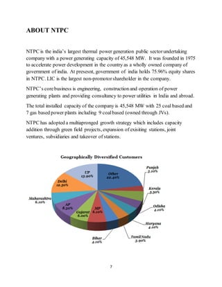
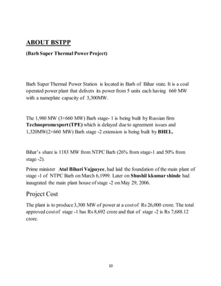
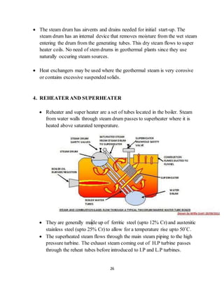
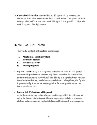
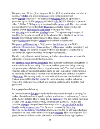
Steam condensing
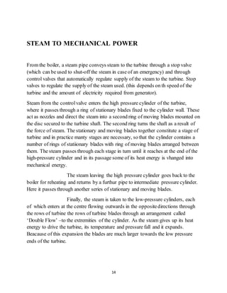
The condenser condensesthe steam from the exhaust of the turbine into
liquid to allow it to be pumped. If the condenser can be made cooler, the
pressureof the exhaust steam is reduced and efficiency of the cycle increases.
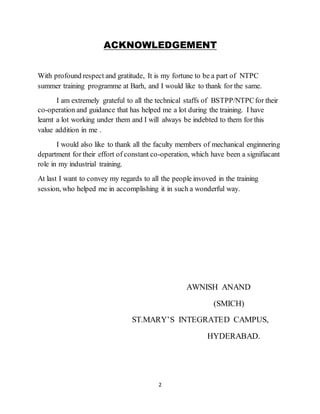
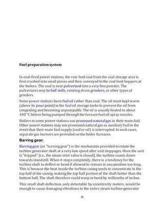
Diagram of a typical water-cooled surfacecondenser.
The surfacecondenser is a shell and tube heat exchanger in which cooling
water is circulated through the tubes.[7][11][12][13] The exhaust steam from the
low pressureturbineentersthe shell where it is cooled and converted to
condensate(water) by flowingover the tubes as shown in the adjacent
diagram. Such condensersuse steam ejectors or rotary motor-driven exhausts
for continuousremovalof air and gases from the steam side to
maintainvacuum.
For best efficiency, the temperaturein the condenser mustbe kept as low as
practical in order to achieve the lowest possible pressurein the condensing
steam. Since the condenser temperaturecan almost alwaysbe kept
significantly below 100 °C where the vapor pressure of water is muchless
than atmospheric pressure, the condenser generally worksunder vacuum.
Thus leaks of non-condensibleair into the closed loop mustbe prevented.
Typically the cooling water causes the steam to condenseat a temperatureof
about 35 °C (95 °F) and that creates an absolute pressure in the condenser of
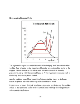
about 2–7 kPa(0.59–2.07inHg), i.e. a vacuum of about −95 kPa(−28 inHg)
relative to atmosphericpressure. The large decrease in volumethat occurs](https://image.slidesharecdn.com/0f9cd220-1bb6-4dff-85ec-d90610f0364e-160919124114/85/ntpc-32-320.jpg)
![40
technology. Still, the majority of coal-fired power plantsin the world do not
have these facilities.[citation needed] Legislation in Europehas been efficient to
reducefluegas pollution. Japan has been usingfluegas cleaning technology
for over 30 yearsand the US has been doingthe same for over 25 years. China
is now beginning to grapplewith the pollution caused by coal-fired power
plants.
Where required by law, the sulfur and nitrogen oxide pollutants are removed
by stack gas scrubbers which use a pulverized limestoneor other alkaline wet
slurry to removethose pollutantsfrom the exit stack gas. Other devicesuse
catalysts to removeNitrousOxide compoundsfrom theflue gas stream. The
gas travelling up the fluegas stack may by this time have dropped to about
50 °C (120 °F). A typicalflue gas stack may be 150–180 metres(490–590ft)
tall to dispersethe remainingfluegas componentsin the atmosphere. The
tallest fluegas stack in the world is 419.7 metres(1,377 ft)tall at the GRES-
2 power plant in Ekibastuz, Kazakhstan.](https://image.slidesharecdn.com/0f9cd220-1bb6-4dff-85ec-d90610f0364e-160919124114/85/ntpc-40-320.jpg)


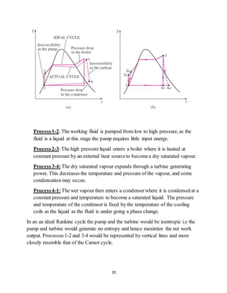
This document is a summer training report submitted by Awnish Anand, a 3rd year mechanical engineering student at SMIC Hyderabad, after completing a 4-week internship at the National Thermal Power Corporation (NTPC) plant in Barh, Bihar from June 1-31, 2016. The report provides an overview of NTPC, details about the Barh Super Thermal Power Plant where the training took place, and describes the basic steps of electricity generation from coal as observed during the internship. It also includes sections on maintenance departments at the plant and the Rankine cycle of thermal power generation.


