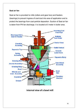
Downloaded 437 times
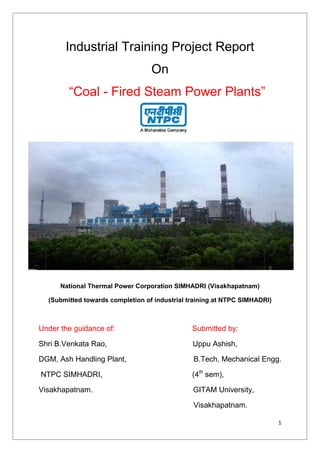


The document is an industrial training project report on coal-fired steam power plants at NTPC Simhadri, Visakhapatnam, detailing the training schedule and activities completed by the author, Uppu Ashish, during his industrial training. It provides an overview of NTPC's operations, its significance in India's power sector, and the structure of the Simhadri power plant, which has a total capacity of 2000 MW divided into four 500 MW units. Additionally, the report includes acknowledgments, a certificate of training completion, and a comprehensive table of contents covering various technical aspects and operations of the power plant.


