Downloaded 46 times


![REFERENCE
• [1] L. Hu, J. W. Choi, Y. Yang, S. Jeong, F. La Mantia, F. Cui, and Y. Cui, “Highly conductive paper for
energy-storage devices,” Proc. Nat. Academy Sci., vol. 106, pp. 21490–21494, 2009.
• [2] L.Hu,H.Wu,F. LaMantia,Y.Yang,andY.Cui,“Thin,flexiblesecondary Li-ion paper batteries,” ACS
Nano, vol. 4, pp. 5843–5848, 2010.
• [3]S.Stewart,P.Albertus,V.Srinivasan,I.Plitz,N.Pereira,G.Amatucci,and J.Newman,“Optimizing the
performance of lithium titanate spinel paired with activated carbon or iron phosphate,” J. Electrochem.
Soc., vol. 155, pp. A253–A261, 2008.
• [4] L. Hu, D. S. Hecht, and G. Gruner, “Percolation in transparent and conducting carbon nanotube
networks,” Nano Lett., vol. 4, pp. 2513–2517, 2004.
• [5] R. S. Morris, B. G. Dixon, T. Gennett, R. Raffaelle, and M. J. Heben, “High-energy, rechargeable
Li-ion battery based on carbon nanotube technology,” J. Power Sources, vol. 138, pp. 277–280, 2004.](https://image.slidesharecdn.com/microbatteries-170324162300/75/Paper-based-Lithium-ion-batteries-using-CNT-coated-wood-microfibers-23-2048.jpg)
![[6] http://ieeexplore.ieee.org/document/6481448/
[7] https://www.scientificamerican.com/article/carbon-nanotubes-turn-off/
[8] https://electrosome.com/paper-battery/
[9] https://www.edgefx.in/paper-battery-working-and-construction/
[10] T. Takeuchi, T. Kyuna, H. Morimoto, and S. Tobishima, “Influence of surface modification of LiCoO2
by organic compounds on electrochemical and thermal properties of Li/LiCoO2 rechargeable cells,” J.
Power Sources, vol. 196, pp. 2790–2801, Nov. 2010.](https://image.slidesharecdn.com/microbatteries-170324162300/75/Paper-based-Lithium-ion-batteries-using-CNT-coated-wood-microfibers-24-2048.jpg)


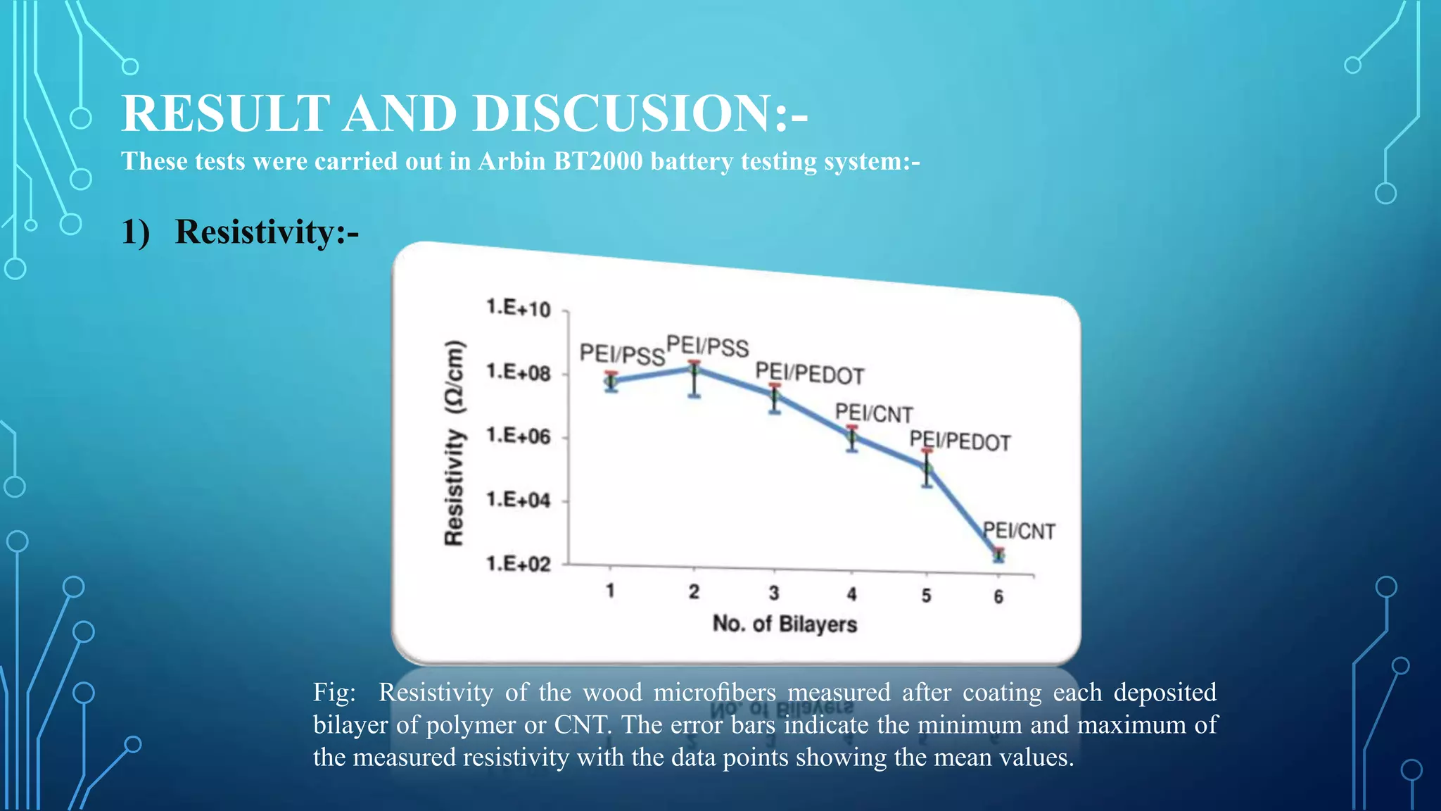
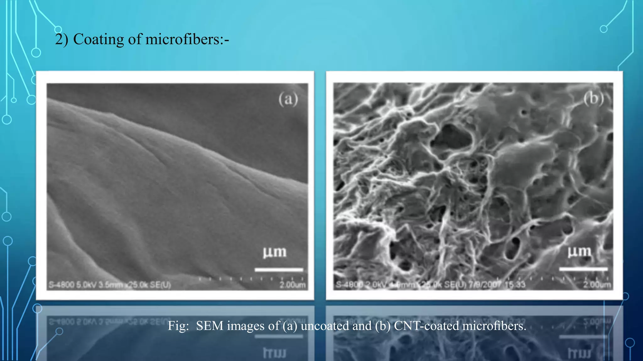
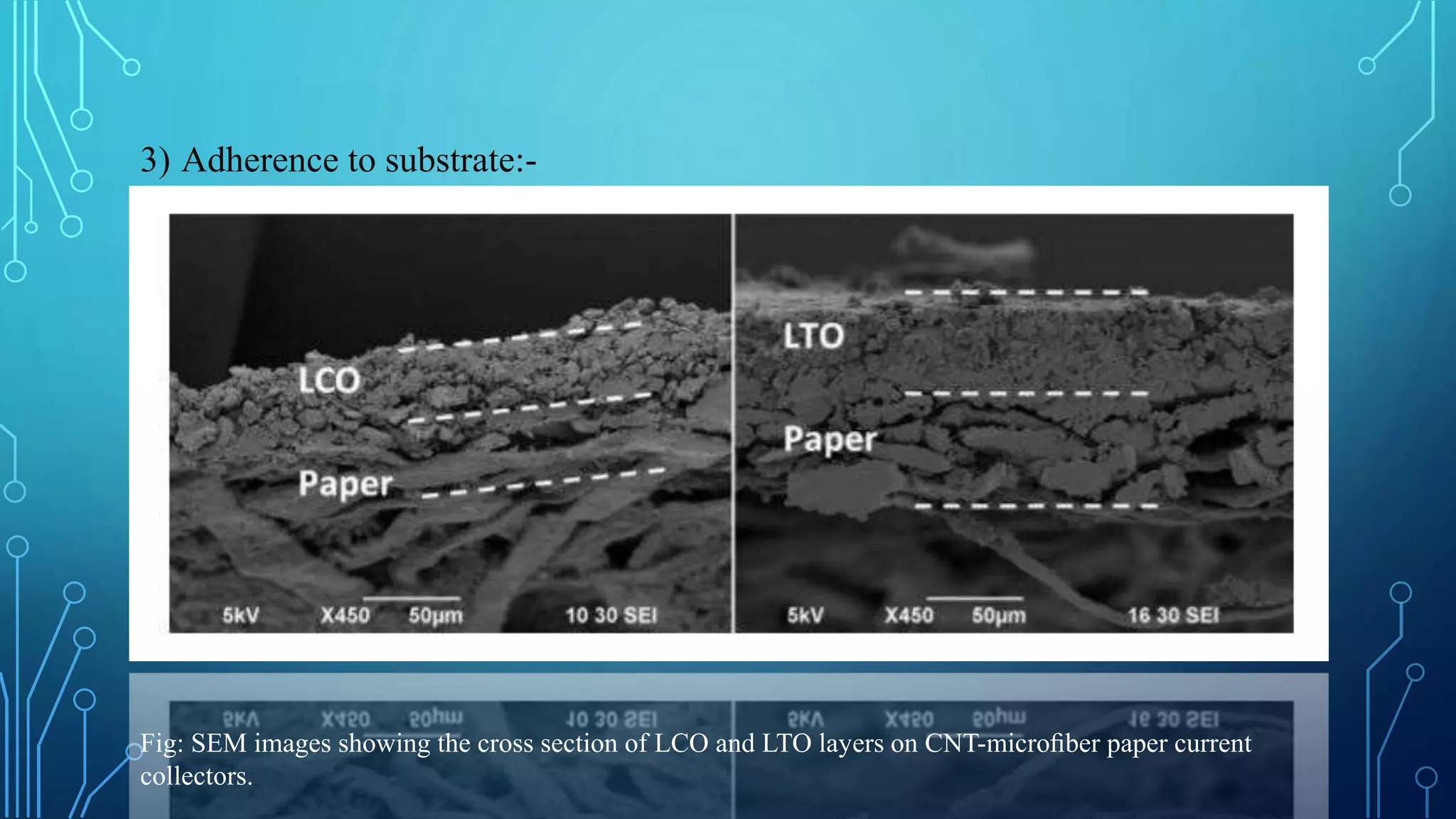
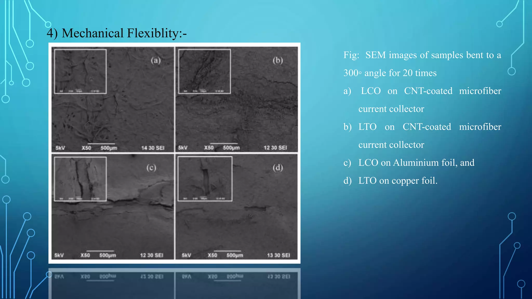
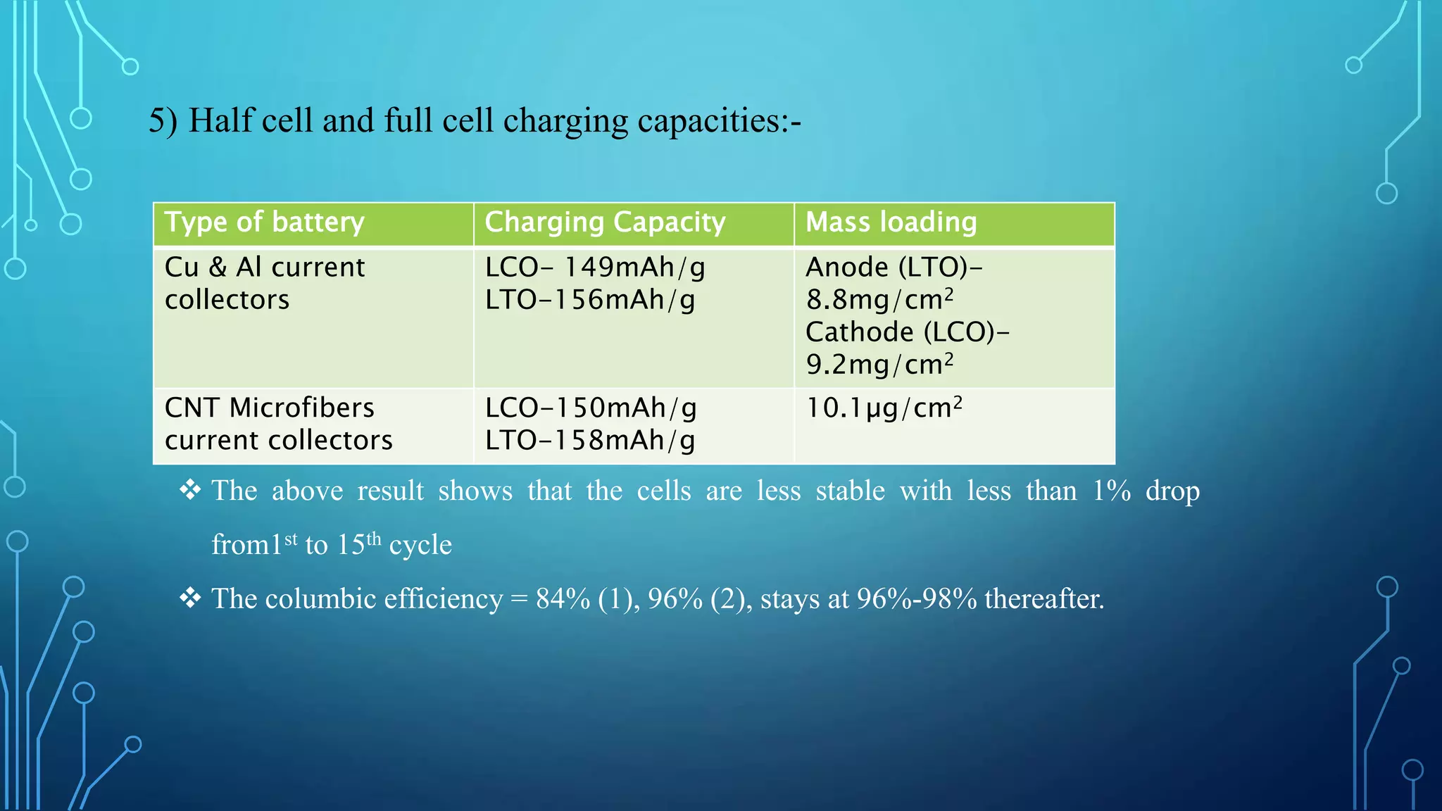
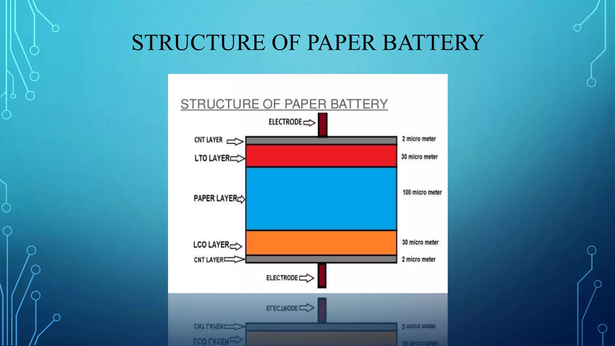
The document discusses the development of lithium-ion batteries using flexible paper-based current collectors made from wood microfibers coated with carbon nanotubes, which provide flexibility, environmental friendliness, and low costs. It highlights the advantages of paper batteries, including their application in electronics and medical devices, and concludes that these batteries have capacities comparable to traditional batteries, with potential for next-generation applications. Safety, lifecycle, and environmental benefits are emphasized along with detailed descriptions of the battery fabrication and testing process.


