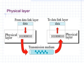
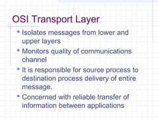
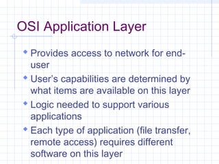
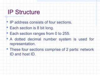
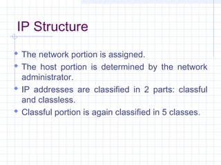
Outline
 Introduction of OSI model
 Layers of OSI model
 Addressing Schemes in OSI model
 Internet Protocol
What is OSI?
 Developed by the International Standard
Organization (ISO) in 1977.
 The primary architectural model for inter computer
communications.
 A conceptual model composed of seven layers, each
specifying particular network functions.
 Describes how information from a software
application in one computer moves through a network
medium to a software application in another
computer.
Why Study OSI?
 Still an excellent model for
conceptualizing and understanding
protocol architectures
 Key points:
 Modular
 Hierarchical
OSI Lower Layers
 Physical – Layer 1
 Data Link – Layer 2
 Network – Layer 3
OSI Physical Layer
 Responsible for transmission of bits
 Responsible for the actual physical
connection between the devices.
 Always implemented through hardware
 Encompasses mechanical, electrical,
and functional interfaces
 e.g. RS-232
Physical layer
OSI Data Link Layer
 Responsible for error-free, reliable
transmission of data
 Flow control, error correction
 e.g. HDLC
OSI Data Link Layer
IEEE has subdivided data link layer into two sub-layers.
OSI Network Layer
 Responsible for routing of messages
through network
 Concerned with type of switching used
 Handles routing between networks, as well
as through packet-switching networks
 Concerned with exchange of data between
computer and network
 Includes addressing, routing, prioritizing,
etc
OSI Upper Layers
 Transport
 Session
 Presentation
 Application
OSI Transport Layer
 Isolates messages from lower and
upper layers
 Monitors quality of communications
channel
 It is responsible for source process to
destination process delivery of entire
message.
 Concerned with reliable transfer of
information between applications
Transport Layer
 Breaks down message size
 Make sure that the message is delivered
to the correct process on destination
machine.
 Includes aspects like flow control and
error checking
OSI Session Layer
 Establishes logical connections
between systems.
 Manages log-ons, password exchange,
log-offs.
 Terminates connection at end of
session.
OSI Presentation Layer
 Provides format and code conversion
services.
 Examples
 File conversion from EBCDIC to ASCII-
coded files.
 Invoking character sequences to generate
bold, italics, etc on a printer.
OSI Application Layer
 Provides access to network for end-
user
 User’s capabilities are determined by
what items are available on this layer
 Logic needed to support various
applications
 Each type of application (file transfer,
remote access) requires different
software on this layer
THE INTERNET PROTOCOL
What is an IP address?
 It is a logical address.
 It specifies the location of a client on the
internet.
 It is a unique identifier.
IP Usage
 It is helpful in connecting one device to another.
 It helps in the sharing of files on the network.
IP Structure
 IP address consists of four sections.
 Each section is 8 bit long.
 Each section ranges from 0 to 255.
 A dotted decimal number system is used for
representation.
 These four sections comprise of 2 parts: network
ID and host ID.
IP Structure
 The network portion is assigned.
 The host portion is determined by the network
administrator.
 IP addresses are classified in 2 parts: classful
and classless.
 Classful portion is again classified in 5 classes.
Class A IP Address
 It consist of 8 bits of network ID and 24 bits of
host ID.
 It’s minimum limit is 0.
 It’s maximum limit is 127.
Class B IP Address
 It consist of 16 bits of network ID and 16 bits of
host ID.
 It’s minimum limit is 128.
 It’s maximum limit is 191.
Class C IP Address
 It consists of 24 bits of network ID and 8 bits of
host ID.
 It’s minimum limit is 192.
 It’s maximum limit is 223.
Class D and Class E
Class D
 Class D is reserved for multi-casting.
 It is assigned to a group of networks and not just
a unique address.
Class E
 Class E is reserved for future use.
Reserved Addresses
 Any IP starting with 0 cannot be allotted to any
machine.
 Any IP starting with 127 indicates that the
machine is subjected to loop back or internal
testing.
 Any IP having all host ID as 0 cannot be
assigned to any machine.
 All host bits as 1 cannot be used.
Subnetting
 Subnet Mask: This is the mask which helps in
determining the number of bits for network. In
other words, it helps in determining network ID
of an address.
 Chopping up of a network into a number of
smaller networks is called subnetting.
Subnetting- Why?
 Division of networks.
 Greater number of networks.
 Simplified addressing.
The Upgradation
 The version 4 is running out.
 It is being upgraded to IPv6.
 IPv6 is represented in hexadecimal form.
 IPv4 has only 32 bits whereas IPv6 has 128 bits.
 IPv6 has security features also.
OSI Application Layer
 Provides access to network for end-
user.
 User’s capabilities are determined by
what items are available on this layer.
 Peforms functions like synchronizing
communication.

Osi & ip presentation

  • 1.
    Outline  Introduction ofOSI model  Layers of OSI model  Addressing Schemes in OSI model  Internet Protocol
  • 2.
    What is OSI? Developed by the International Standard Organization (ISO) in 1977.  The primary architectural model for inter computer communications.  A conceptual model composed of seven layers, each specifying particular network functions.  Describes how information from a software application in one computer moves through a network medium to a software application in another computer.
  • 3.
    Why Study OSI? Still an excellent model for conceptualizing and understanding protocol architectures  Key points:  Modular  Hierarchical
  • 5.
    OSI Lower Layers Physical – Layer 1  Data Link – Layer 2  Network – Layer 3
  • 6.
    OSI Physical Layer Responsible for transmission of bits  Responsible for the actual physical connection between the devices.  Always implemented through hardware  Encompasses mechanical, electrical, and functional interfaces  e.g. RS-232
  • 7.
  • 8.
    OSI Data LinkLayer  Responsible for error-free, reliable transmission of data  Flow control, error correction  e.g. HDLC
  • 9.
    OSI Data LinkLayer IEEE has subdivided data link layer into two sub-layers.
  • 10.
    OSI Network Layer Responsible for routing of messages through network  Concerned with type of switching used  Handles routing between networks, as well as through packet-switching networks  Concerned with exchange of data between computer and network  Includes addressing, routing, prioritizing, etc
  • 11.
    OSI Upper Layers Transport  Session  Presentation  Application
  • 12.
    OSI Transport Layer Isolates messages from lower and upper layers  Monitors quality of communications channel  It is responsible for source process to destination process delivery of entire message.  Concerned with reliable transfer of information between applications
  • 13.
    Transport Layer  Breaksdown message size  Make sure that the message is delivered to the correct process on destination machine.  Includes aspects like flow control and error checking
  • 14.
    OSI Session Layer Establishes logical connections between systems.  Manages log-ons, password exchange, log-offs.  Terminates connection at end of session.
  • 15.
    OSI Presentation Layer Provides format and code conversion services.  Examples  File conversion from EBCDIC to ASCII- coded files.  Invoking character sequences to generate bold, italics, etc on a printer.
  • 16.
    OSI Application Layer Provides access to network for end- user  User’s capabilities are determined by what items are available on this layer  Logic needed to support various applications  Each type of application (file transfer, remote access) requires different software on this layer
  • 17.
  • 18.
    What is anIP address?  It is a logical address.  It specifies the location of a client on the internet.  It is a unique identifier.
  • 19.
    IP Usage  Itis helpful in connecting one device to another.  It helps in the sharing of files on the network.
  • 20.
    IP Structure  IPaddress consists of four sections.  Each section is 8 bit long.  Each section ranges from 0 to 255.  A dotted decimal number system is used for representation.  These four sections comprise of 2 parts: network ID and host ID.
  • 21.
    IP Structure  Thenetwork portion is assigned.  The host portion is determined by the network administrator.  IP addresses are classified in 2 parts: classful and classless.  Classful portion is again classified in 5 classes.
  • 22.
    Class A IPAddress  It consist of 8 bits of network ID and 24 bits of host ID.  It’s minimum limit is 0.  It’s maximum limit is 127.
  • 23.
    Class B IPAddress  It consist of 16 bits of network ID and 16 bits of host ID.  It’s minimum limit is 128.  It’s maximum limit is 191.
  • 24.
    Class C IPAddress  It consists of 24 bits of network ID and 8 bits of host ID.  It’s minimum limit is 192.  It’s maximum limit is 223.
  • 25.
    Class D andClass E Class D  Class D is reserved for multi-casting.  It is assigned to a group of networks and not just a unique address. Class E  Class E is reserved for future use.
  • 26.
    Reserved Addresses  AnyIP starting with 0 cannot be allotted to any machine.  Any IP starting with 127 indicates that the machine is subjected to loop back or internal testing.  Any IP having all host ID as 0 cannot be assigned to any machine.  All host bits as 1 cannot be used.
  • 27.
    Subnetting  Subnet Mask:This is the mask which helps in determining the number of bits for network. In other words, it helps in determining network ID of an address.  Chopping up of a network into a number of smaller networks is called subnetting.
  • 28.
    Subnetting- Why?  Divisionof networks.  Greater number of networks.  Simplified addressing.
  • 29.
    The Upgradation  Theversion 4 is running out.  It is being upgraded to IPv6.  IPv6 is represented in hexadecimal form.  IPv4 has only 32 bits whereas IPv6 has 128 bits.  IPv6 has security features also.
  • 30.
    OSI Application Layer Provides access to network for end- user.  User’s capabilities are determined by what items are available on this layer.  Peforms functions like synchronizing communication.