Downloaded 676 times
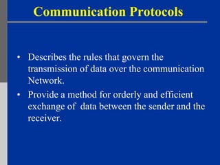

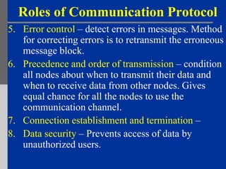


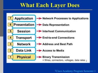


Communication protocols define the rules for transmitting data over a network. They provide an orderly method for exchanging data between sender and receiver. The document then describes the key roles of communication protocols such as data sequencing, routing, formatting, flow control, error control, transmission order, and connection establishment/termination. It also summarizes the OSI model which outlines 7 layers that interact to send data between computers, and describes what each layer is responsible for.