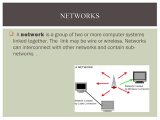
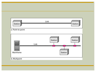
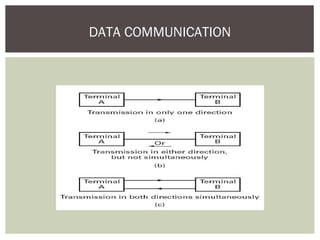
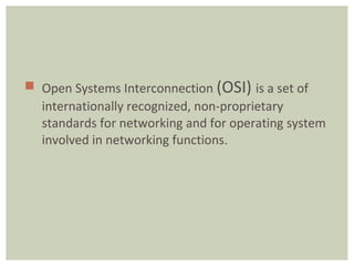
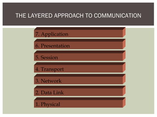
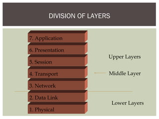
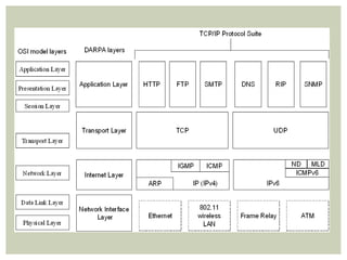
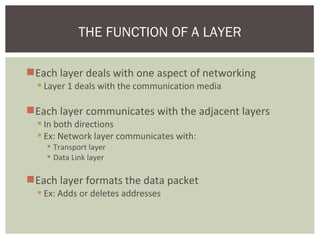
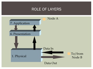
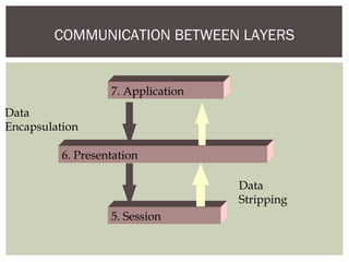
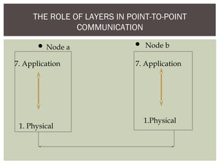
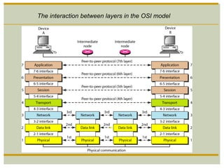
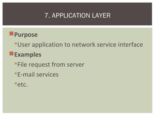
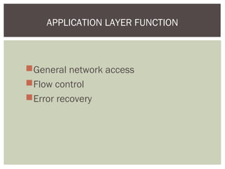
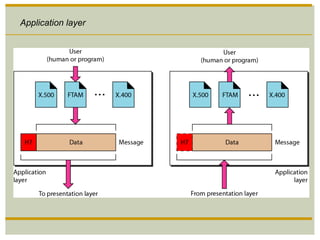
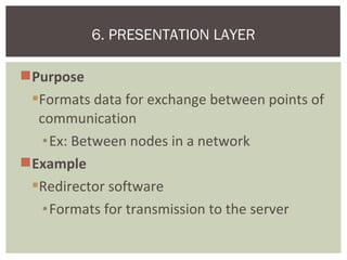
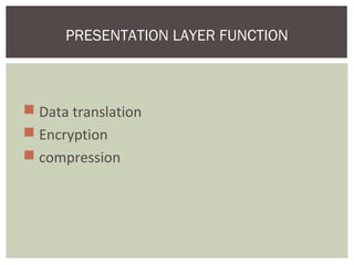
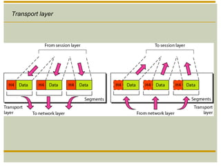
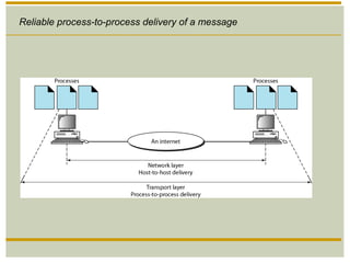
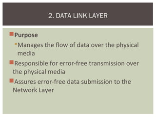
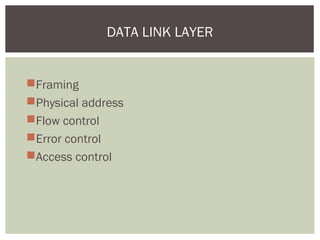
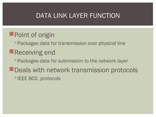
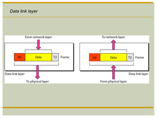
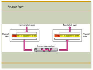
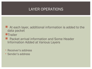
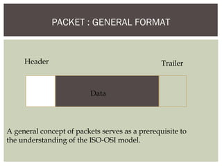
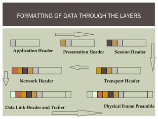
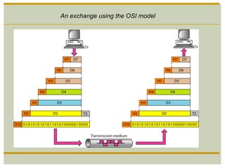
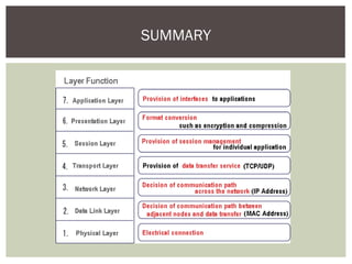
TOPIC:
OSI MODEL
Submitted by:
Shahreen Gul (1544-BSEE-FET-F11)
Namra Afzal (1528-BSEE-FET-F11)
Irum Fatima (1545-BSEE-FET-F11)
OUTLINE
Network
Division of layers
Layers & their functions
Formatting of data through layer
 A network is a group of two or more computer systems
linked together. The link may be wire or wireless. Networks
can interconnect with other networks and contain sub-
networks .
NETWORKSNETWORKS
DATA COMMUNICATION
 Open Systems Interconnection (OSI) is a set of
internationally recognized, non-proprietary
standards for networking and for operating system
involved in networking functions.
THE LAYERED APPROACH TO COMMUNICATION
7. Application
6. Presentation
5. Session
4. Transport
3. Network
2. Data Link
1. Physical
DIVISION OF LAYERS
Upper Layers
Lower Layers
Middle Layer
7. Application
6. Presentation
5. Session
4. Transport
3. Network
2. Data Link
1. Physical
 protocol is the special set of rules that end
points in a telecommunication connection use when
they communicate
It specify interactions between the communicating
entities.
PROTOCOL
Each layer deals with one aspect of networking
 Layer 1 deals with the communication media
Each layer communicates with the adjacent layers
 In both directions
 Ex: Network layer communicates with:
 Transport layer
 Data Link layer
Each layer formats the data packet
 Ex: Adds or deletes addresses
THE FUNCTION OF A LAYER
ROLE OF LAYERS
7. Application
6. Presentation
1. Physical
Node A
Data Out
Data In
To/from
Node B
COMMUNICATION BETWEEN LAYERS
7. Application
6. Presentation
5. Session
Data
Encapsulation
Data
Stripping
THE ROLE OF LAYERS IN POINT-TO-POINT
COMMUNICATION
7. Application
1. Physical
7. Application
1.Physical
Node a Node b
The interaction between layers in the OSI model
Purpose
User application to network service interface
Examples
File request from server
E-mail services
etc.
7. APPLICATION LAYER
General network access
Flow control
Error recovery
APPLICATION LAYER FUNCTION
Application layer
Purpose
Formats data for exchange between points of
communication
•Ex: Between nodes in a network
Example
Redirector software
•Formats for transmission to the server
6. PRESENTATION LAYER
 Data translation
 Encryption
 compression
PRESENTATION LAYER FUNCTION
Presentation layer
Purpose
Dialog controller
synchronization
5. SESSION LAYER
Synchronization between sender and receiver
Assignment of time for transmission
•Start time
•End time etc.
SESSION LAYER FUNCTION
Session layer
Purpose
Repackage proper and efficient delivery of
packages
•In sequence
•Without duplication
•Error free
4. TRANSPORT LAYER
For sending data
Split long messages
Assemble small messages
On receiving data
Perform the reverse
Send an acknowledgment to the sender
Solve packet problems
During transmission and reception
TRANSPORT LAYER FUNCTION
Transport layer
Reliable process-to-process delivery of a message
Purpose
Addressing and routing the packets
Example application at the router
If the packet size is large, splits into small
packets
3. NETWORK LAYER
Address translation from logical to physical
Routing of data
Based on priority
Best path at the time of transmission
Congestion control
NETWORK LAYER FUNCTION
Network layer
A routing protocol is a protocol that specifies how router
communicate with each other
Enables them to select routes between any two nodes on
computer network
E.g OSPF , RIP
ROUTING PROTOCOL
Purpose
Manages the flow of data over the physical
media
Responsible for error-free transmission over
the physical media
Assures error-free data submission to the
Network Layer
2. DATA LINK LAYER
Framing
Physical address
Flow control
Error control
Access control
DATA LINK LAYER
Point of origin
Packages data for transmission over physical line
Receiving end
Packages data for submission to the network layer
Deals with network transmission protocols
IEEE 802. protocols
DATA LINK LAYER FUNCTION
Data link layer
Improvement to ISO Model
Logical Link Control (LLC) sub-layer
Error and flow control
Media Access Control (MAC) sub-layer
Applies directly to network card communication
Access control
DATA LINK LAYER SUBDIVISION
Network Interface Card driver
MEDIA ACCESS CONTROL APPLICATION
NETWORK
SOFTWARE
NETWORK
CARD
NIC Driver
facilitates data
transfer
Purpose
Deals with the transmission of 0s and 1s over the
physical media
Translation of bits into signals
Example
Pulse duration determination
Transmission synchronization
etc.
1. PHYSICAL LAYER
Physical characteristic
Representation of bits
Synchronization of bits
Physical topolgy
Transmission mode
PHYSICAL LAYER
Encode bits into signals
Carry data from the higher layers
Decode bits into signals
Carry data from to higher layers
PHYSICAL LAYER FUNCTION
Physical layer
 At each layer, additional information is added to the
data packet
Trailer
 Packet arrival information and Some Header
Information Added at Various Layers
• Receiver’s address
• Sender’s address
LAYER OPERATIONS
PACKET : GENERAL FORMAT
Header Trailer
Data
A general concept of packets serves as a prerequisite to
the understanding of the ISO-OSI model.
FORMATTING OF DATA THROUGH THE LAYERS
Application Header Presentation Header Session Header
Transport HeaderNetwork Header
Data Link Header and Trailer Physical Frame Preamble
An exchange using the OSI model
SUMMARY
Thank You

OSI(Open System Interconnection) model

  • 1.
    TOPIC: OSI MODEL Submitted by: ShahreenGul (1544-BSEE-FET-F11) Namra Afzal (1528-BSEE-FET-F11) Irum Fatima (1545-BSEE-FET-F11)
  • 2.
    OUTLINE Network Division of layers Layers& their functions Formatting of data through layer
  • 3.
     A network is agroup of two or more computer systems linked together. The link may be wire or wireless. Networks can interconnect with other networks and contain sub- networks . NETWORKSNETWORKS
  • 5.
  • 6.
     Open SystemsInterconnection (OSI) is a set of internationally recognized, non-proprietary standards for networking and for operating system involved in networking functions.
  • 7.
    THE LAYERED APPROACHTO COMMUNICATION 7. Application 6. Presentation 5. Session 4. Transport 3. Network 2. Data Link 1. Physical
  • 8.
    DIVISION OF LAYERS UpperLayers Lower Layers Middle Layer 7. Application 6. Presentation 5. Session 4. Transport 3. Network 2. Data Link 1. Physical
  • 9.
     protocol isthe special set of rules that end points in a telecommunication connection use when they communicate It specify interactions between the communicating entities. PROTOCOL
  • 11.
    Each layer dealswith one aspect of networking  Layer 1 deals with the communication media Each layer communicates with the adjacent layers  In both directions  Ex: Network layer communicates with:  Transport layer  Data Link layer Each layer formats the data packet  Ex: Adds or deletes addresses THE FUNCTION OF A LAYER
  • 12.
    ROLE OF LAYERS 7.Application 6. Presentation 1. Physical Node A Data Out Data In To/from Node B
  • 13.
    COMMUNICATION BETWEEN LAYERS 7.Application 6. Presentation 5. Session Data Encapsulation Data Stripping
  • 14.
    THE ROLE OFLAYERS IN POINT-TO-POINT COMMUNICATION 7. Application 1. Physical 7. Application 1.Physical Node a Node b
  • 15.
    The interaction betweenlayers in the OSI model
  • 16.
    Purpose User application tonetwork service interface Examples File request from server E-mail services etc. 7. APPLICATION LAYER
  • 17.
    General network access Flowcontrol Error recovery APPLICATION LAYER FUNCTION
  • 18.
  • 19.
    Purpose Formats data forexchange between points of communication •Ex: Between nodes in a network Example Redirector software •Formats for transmission to the server 6. PRESENTATION LAYER
  • 20.
     Data translation Encryption  compression PRESENTATION LAYER FUNCTION
  • 21.
  • 22.
  • 23.
    Synchronization between senderand receiver Assignment of time for transmission •Start time •End time etc. SESSION LAYER FUNCTION
  • 24.
  • 25.
    Purpose Repackage proper andefficient delivery of packages •In sequence •Without duplication •Error free 4. TRANSPORT LAYER
  • 26.
    For sending data Splitlong messages Assemble small messages On receiving data Perform the reverse Send an acknowledgment to the sender Solve packet problems During transmission and reception TRANSPORT LAYER FUNCTION
  • 27.
  • 28.
  • 29.
    Purpose Addressing and routingthe packets Example application at the router If the packet size is large, splits into small packets 3. NETWORK LAYER
  • 30.
    Address translation fromlogical to physical Routing of data Based on priority Best path at the time of transmission Congestion control NETWORK LAYER FUNCTION
  • 31.
  • 32.
    A routing protocolis a protocol that specifies how router communicate with each other Enables them to select routes between any two nodes on computer network E.g OSPF , RIP ROUTING PROTOCOL
  • 33.
    Purpose Manages the flowof data over the physical media Responsible for error-free transmission over the physical media Assures error-free data submission to the Network Layer 2. DATA LINK LAYER
  • 34.
    Framing Physical address Flow control Errorcontrol Access control DATA LINK LAYER
  • 35.
    Point of origin Packagesdata for transmission over physical line Receiving end Packages data for submission to the network layer Deals with network transmission protocols IEEE 802. protocols DATA LINK LAYER FUNCTION
  • 36.
  • 37.
    Improvement to ISOModel Logical Link Control (LLC) sub-layer Error and flow control Media Access Control (MAC) sub-layer Applies directly to network card communication Access control DATA LINK LAYER SUBDIVISION
  • 38.
    Network Interface Carddriver MEDIA ACCESS CONTROL APPLICATION NETWORK SOFTWARE NETWORK CARD NIC Driver facilitates data transfer
  • 39.
    Purpose Deals with thetransmission of 0s and 1s over the physical media Translation of bits into signals Example Pulse duration determination Transmission synchronization etc. 1. PHYSICAL LAYER
  • 40.
    Physical characteristic Representation ofbits Synchronization of bits Physical topolgy Transmission mode PHYSICAL LAYER
  • 41.
    Encode bits intosignals Carry data from the higher layers Decode bits into signals Carry data from to higher layers PHYSICAL LAYER FUNCTION
  • 42.
  • 43.
     At eachlayer, additional information is added to the data packet Trailer  Packet arrival information and Some Header Information Added at Various Layers • Receiver’s address • Sender’s address LAYER OPERATIONS
  • 44.
    PACKET : GENERALFORMAT Header Trailer Data A general concept of packets serves as a prerequisite to the understanding of the ISO-OSI model.
  • 45.
    FORMATTING OF DATATHROUGH THE LAYERS Application Header Presentation Header Session Header Transport HeaderNetwork Header Data Link Header and Trailer Physical Frame Preamble
  • 46.
    An exchange usingthe OSI model
  • 47.
  • 49.

Editor's Notes

  • #2 Open system interconnection
  • #23 Dialog controller ??