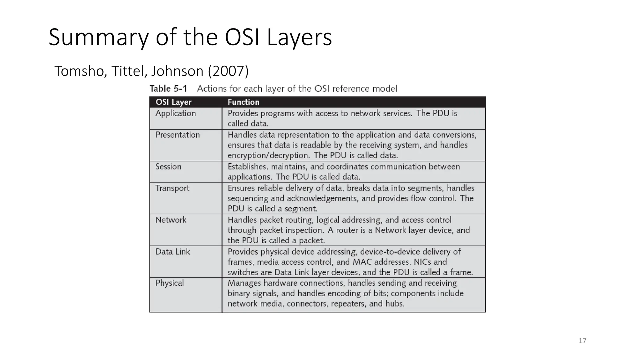
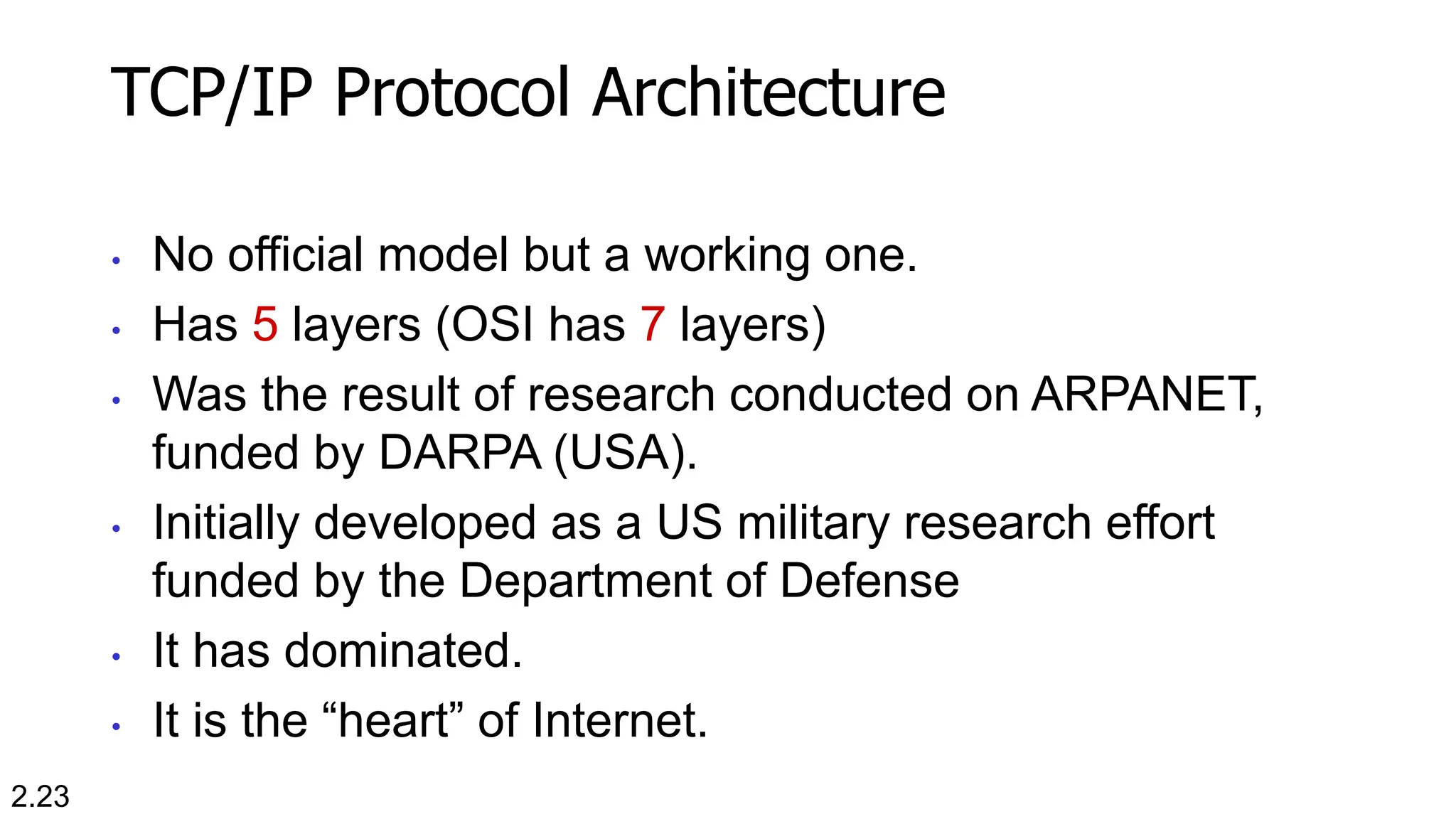
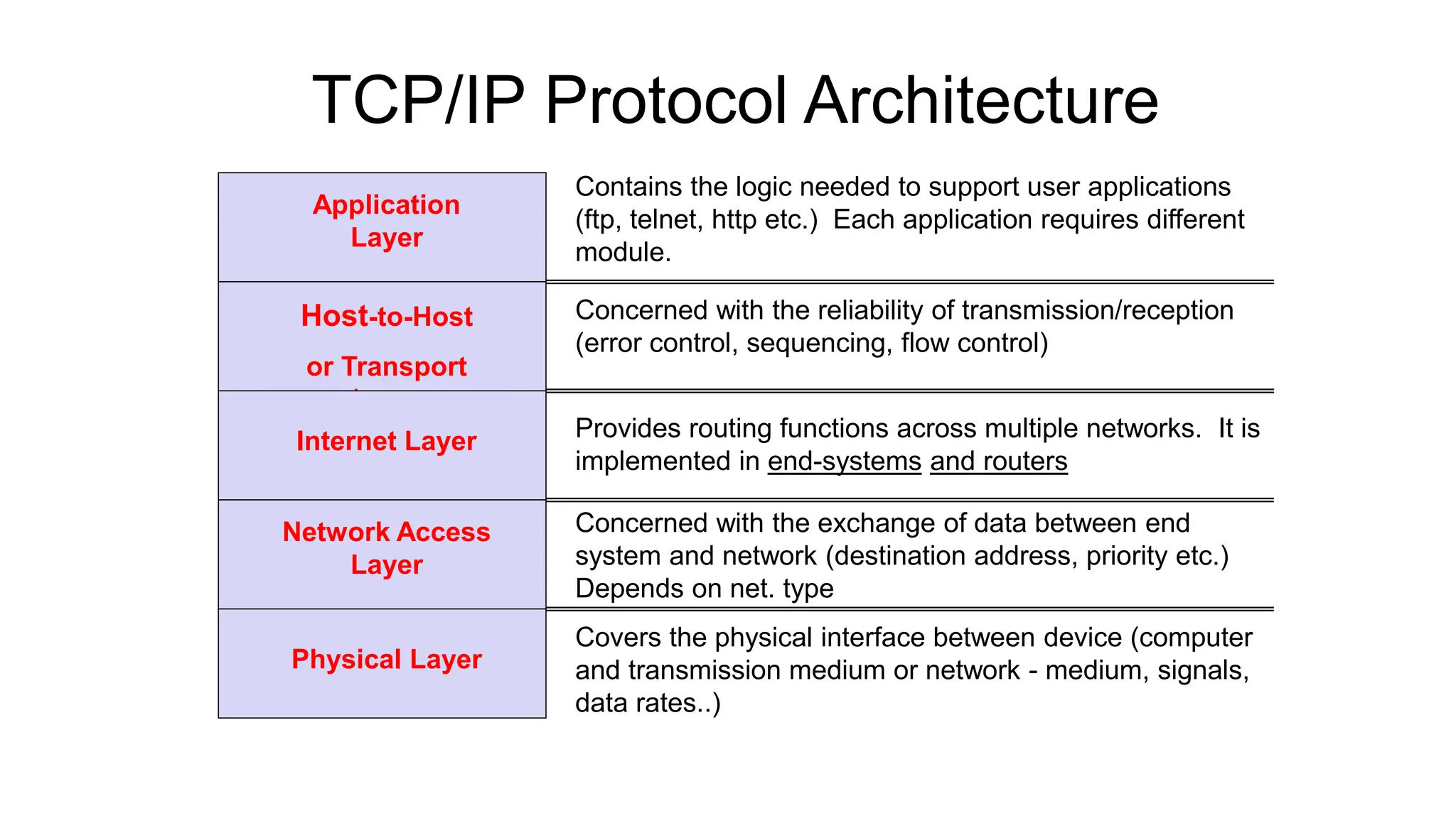
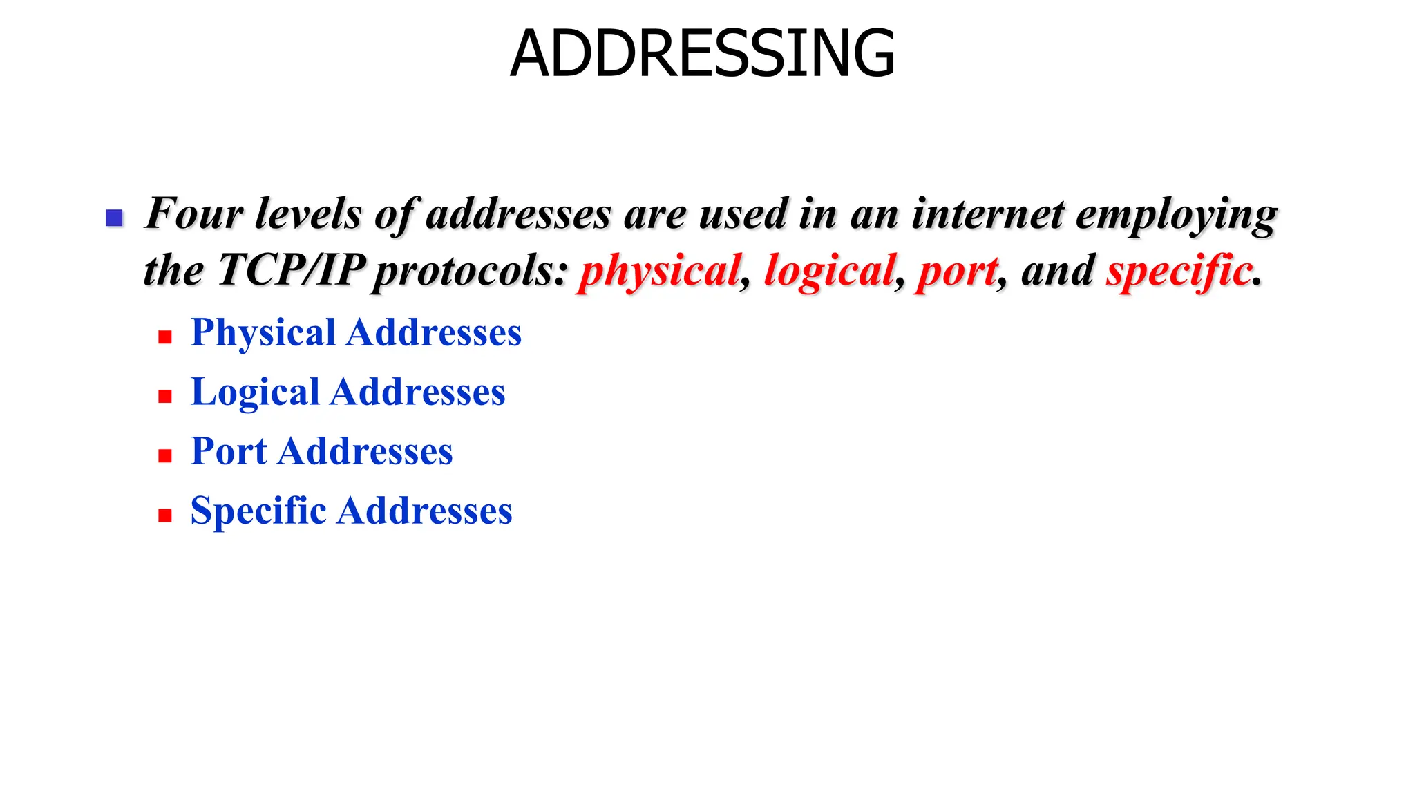
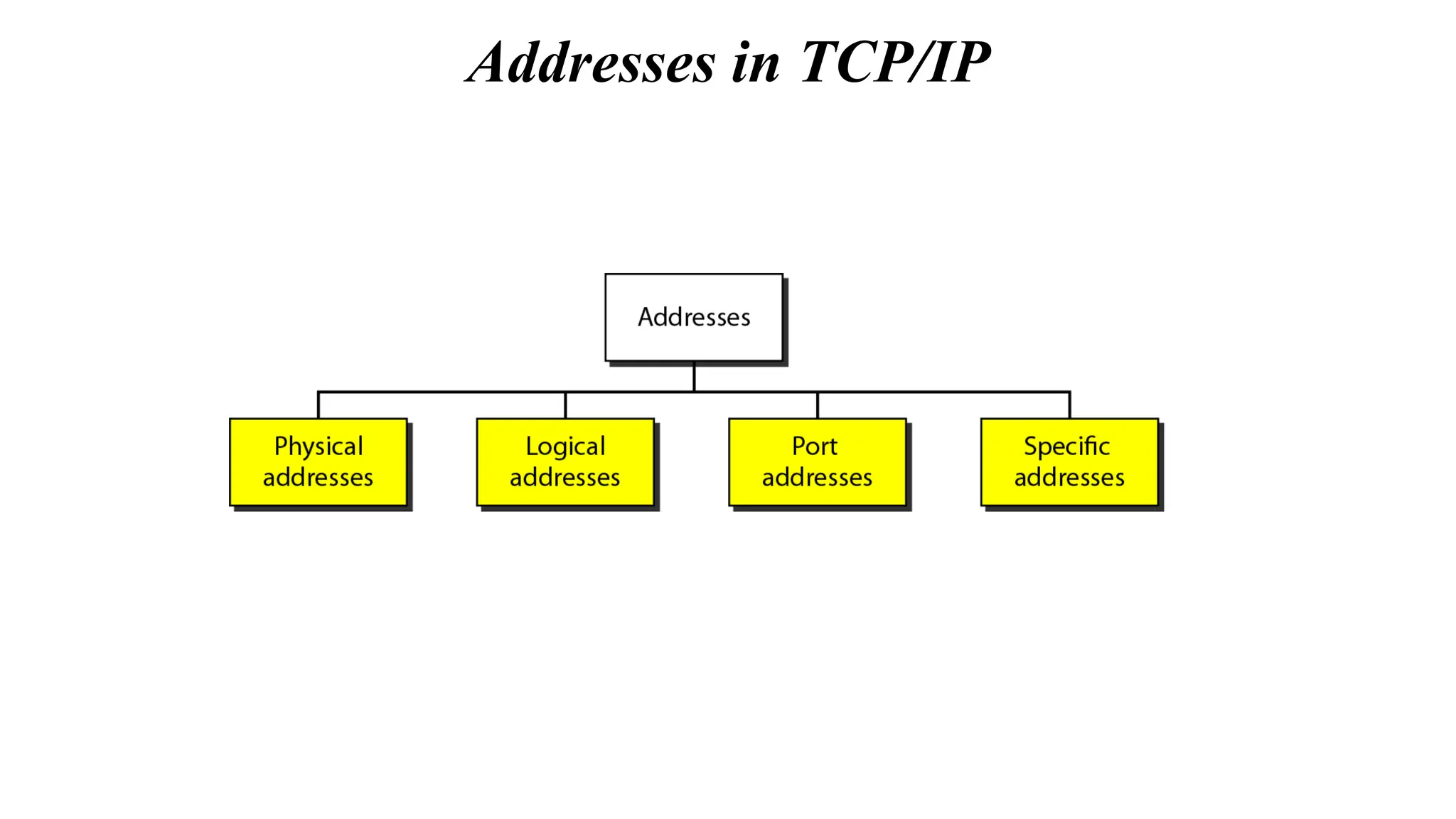
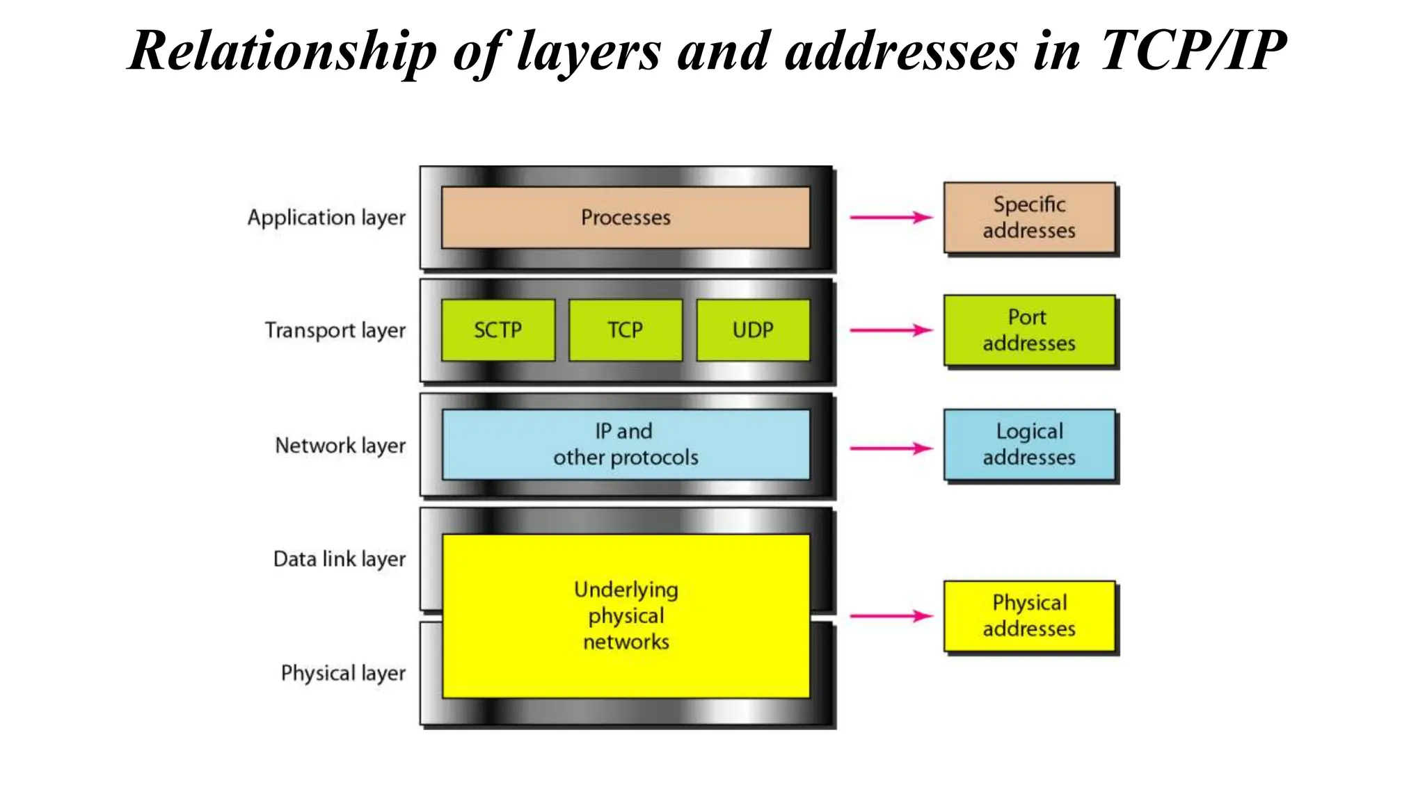
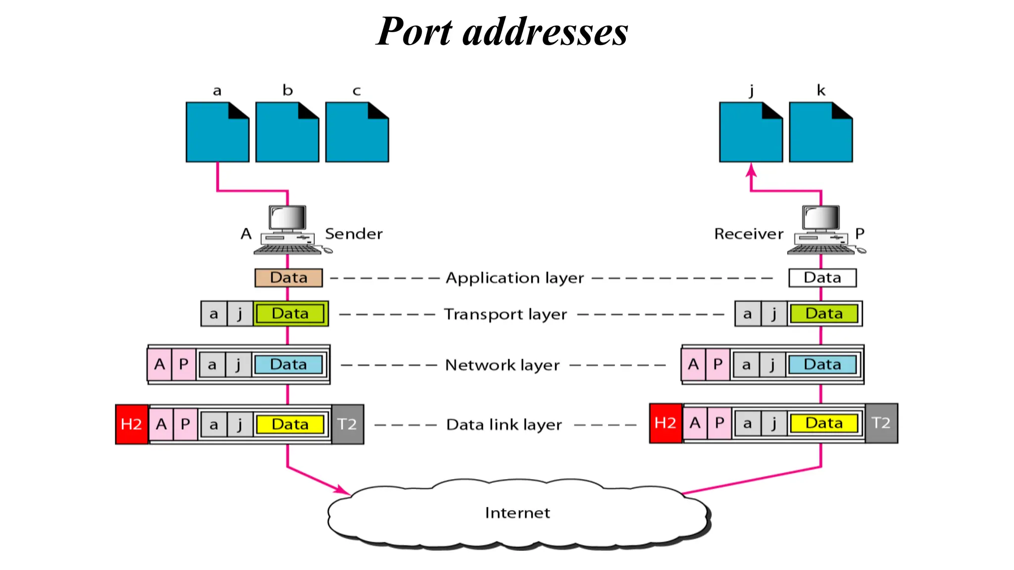
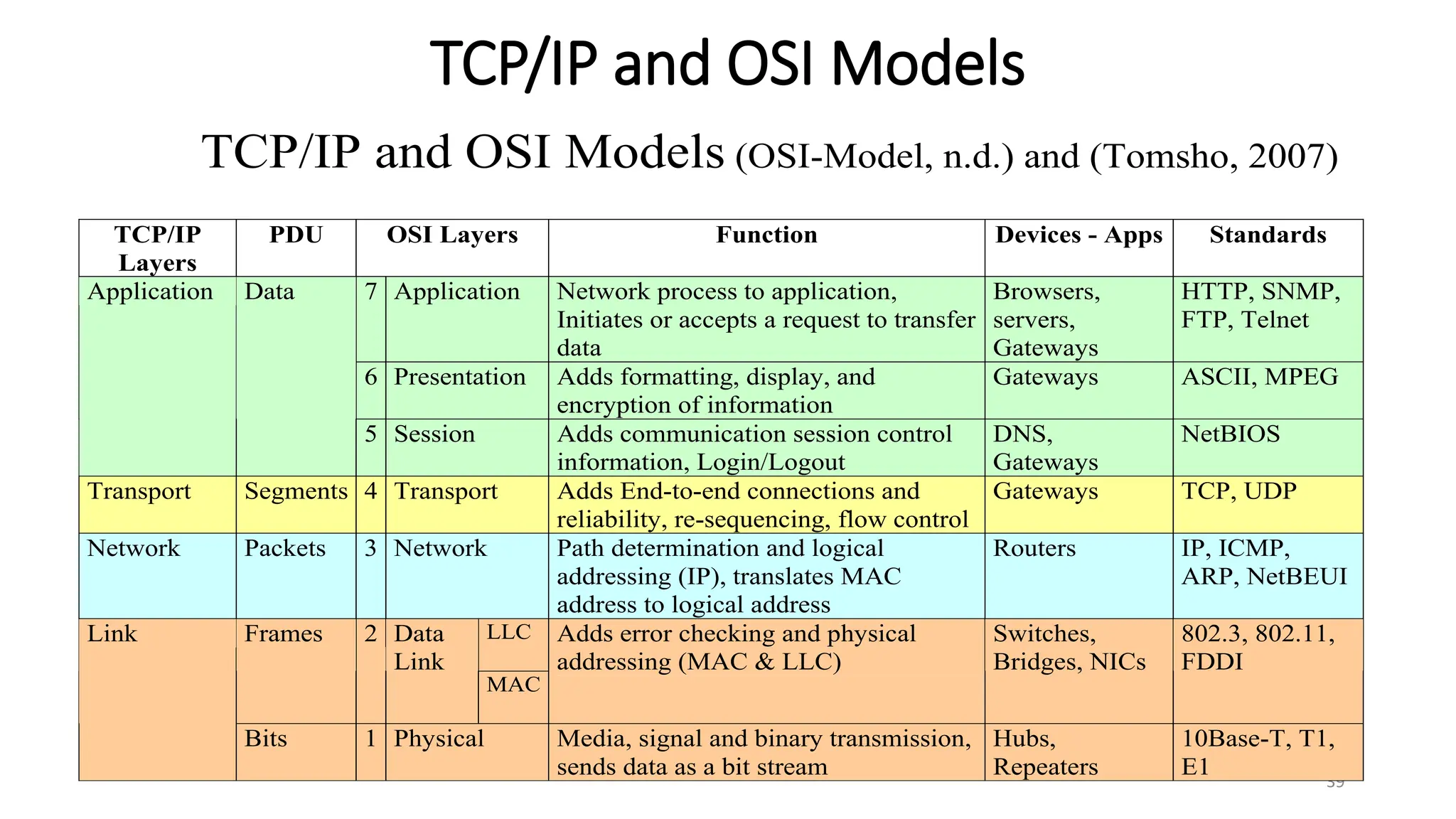
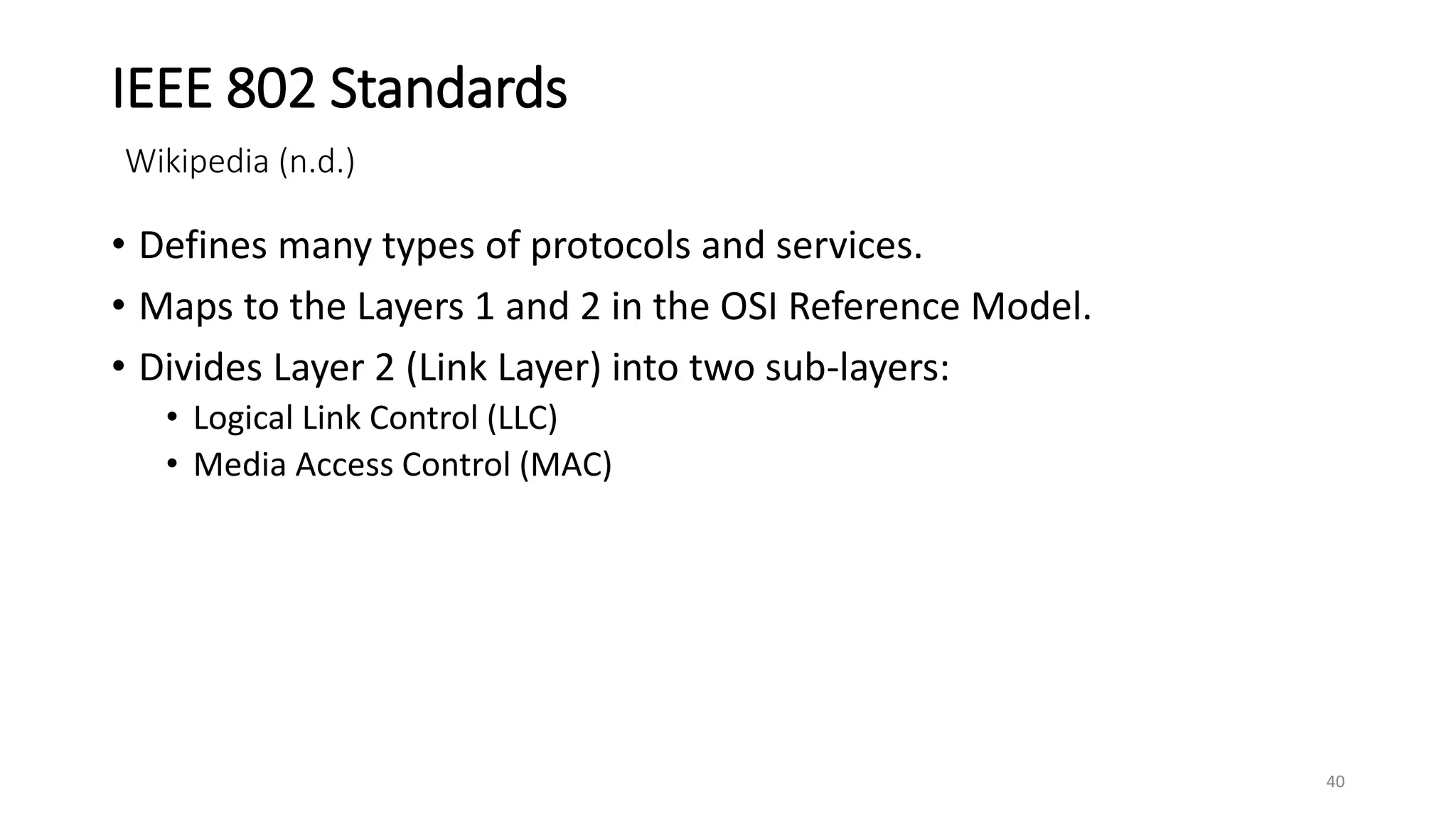
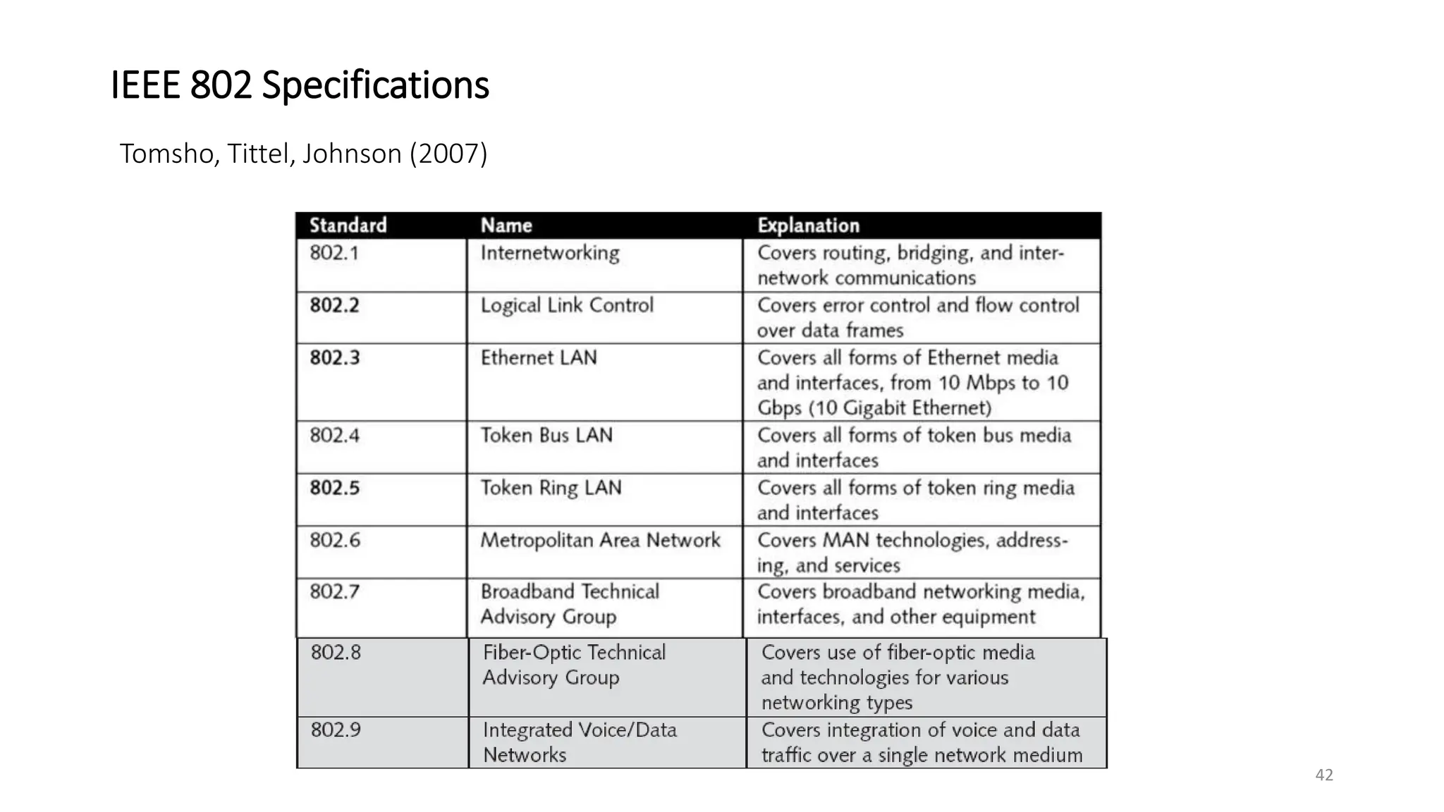
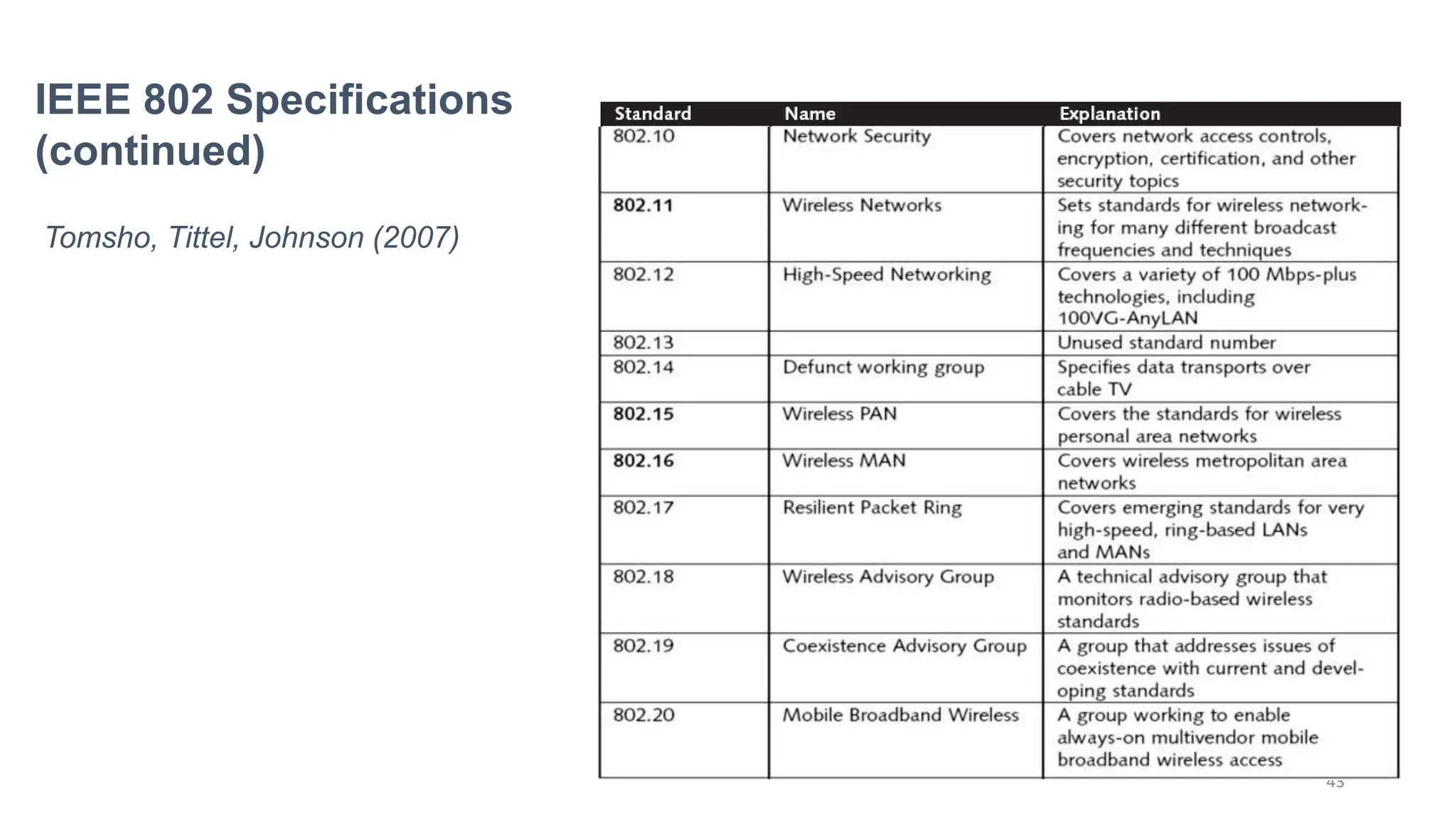
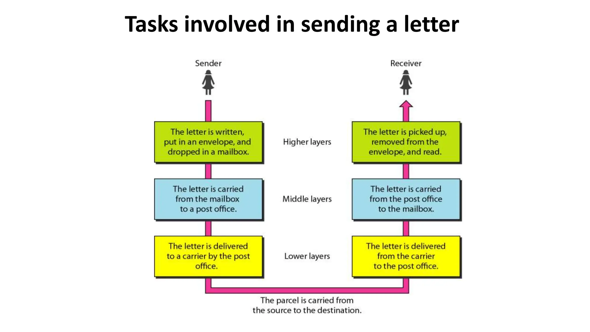
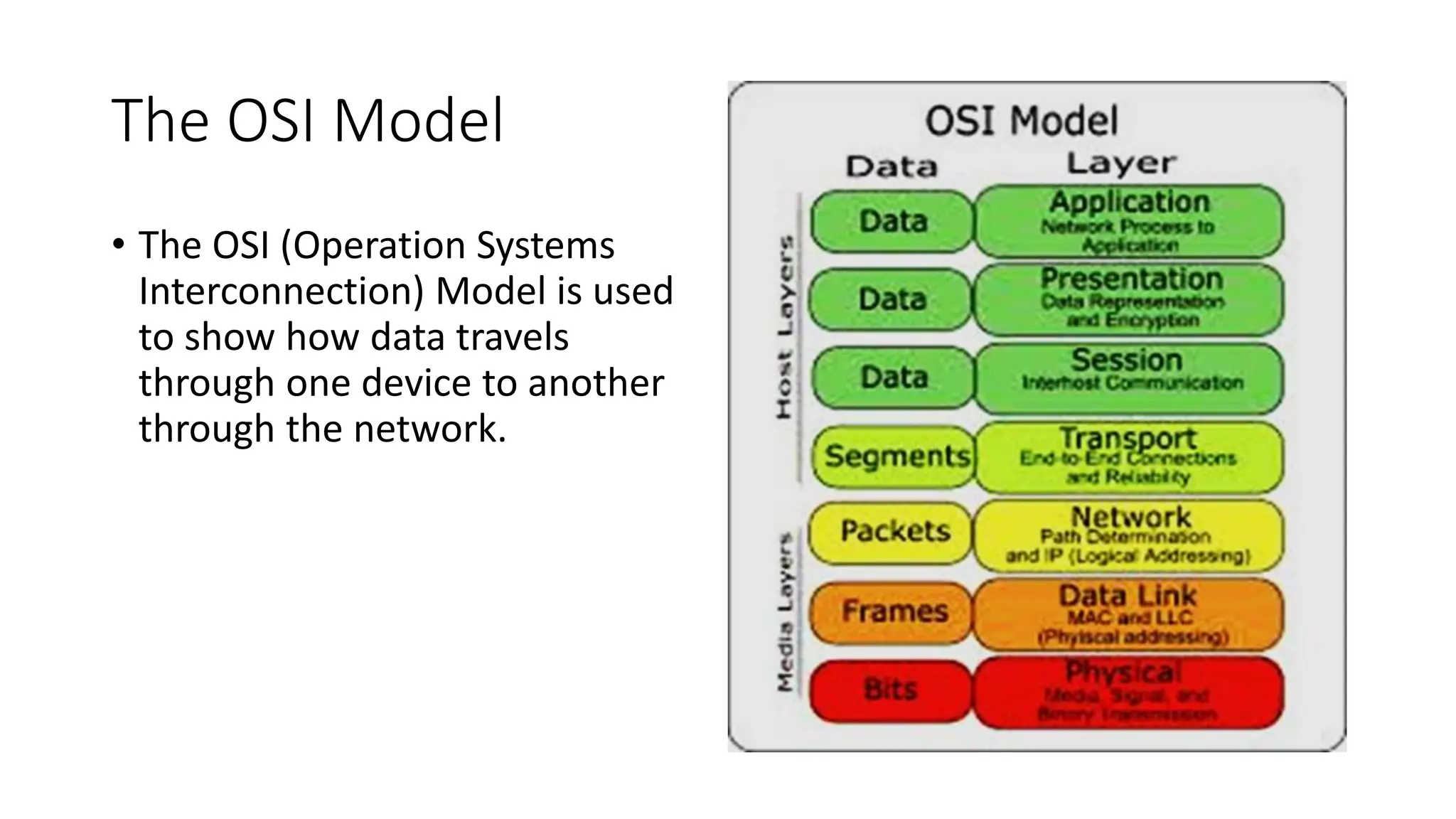
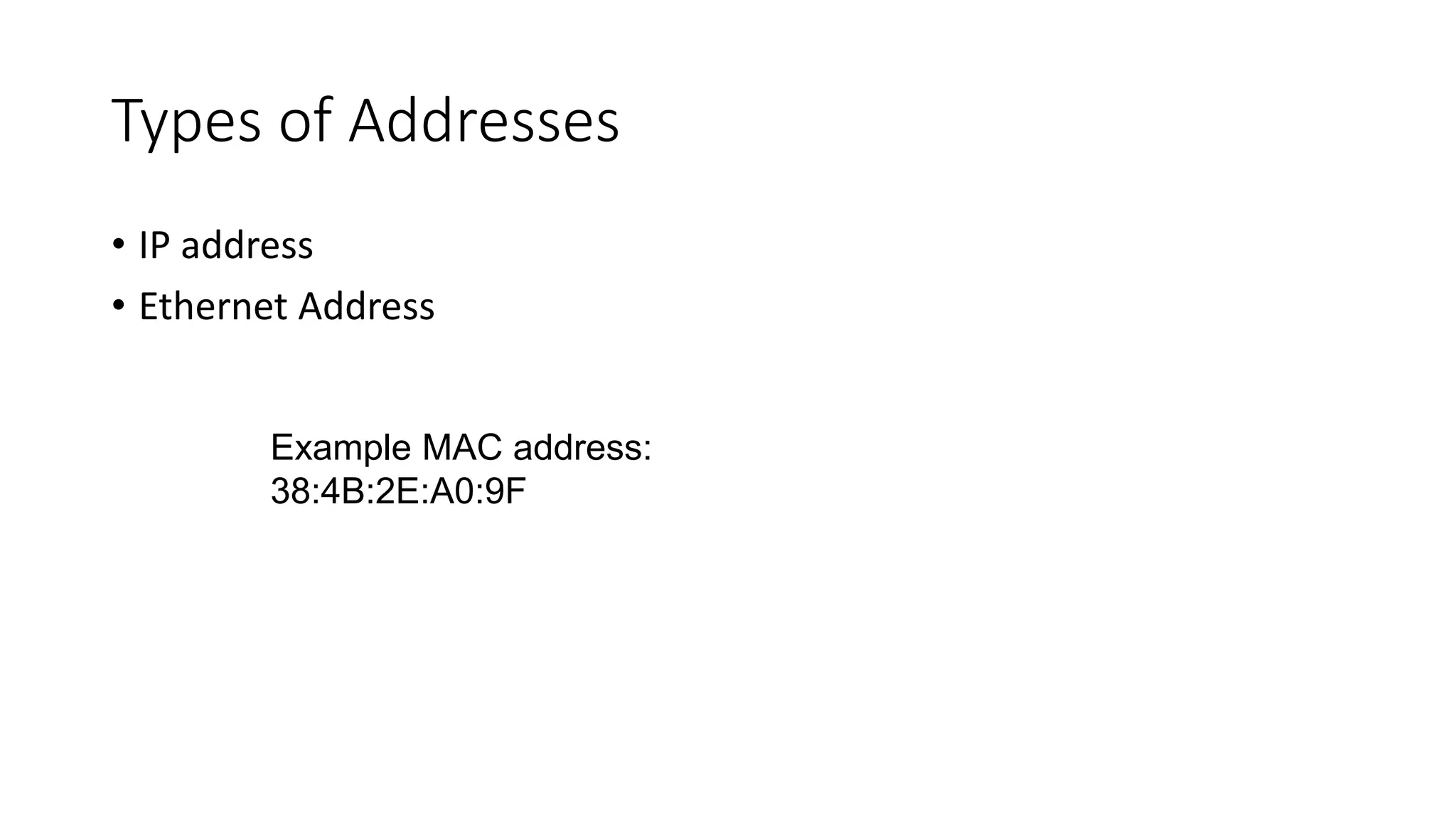
3. 3
Networking Models
• There are many issues to be worked out when attempting to establish
digital communication.
• Just like programming, we decompose a difficult task into smaller (yet
easier) tasks
• 2 dominate networking models are used to decompose the problem
networking:
• OSI: Open Systems Interconnection (OSI) networking suite
• IEEE 802: family of standards
4. 4
OSI and IEEE 802
Tomsho, Tittel, Johnson (2007)
• The IEEE defined a set of LAN standards to ensure network interface and cabling compatibility
• Project 802 (inception on February (2) of 1980)
• Concentrates on standards that describe a network’s physical elements
• NICs, cables, connectors, signaling technologies, media access control
• OSI model was not standardized until 1983–1984
• IEEE 802 standards predate the model
• Both were developed in collaboration and are compatible with one another
5. OSI Reference Model
• OSI Reference Model - internationally standardised network
architecture.
• OSI = Open Systems Interconnection: deals with open systems, i.e.
systems open for communications with other systems.
• Specified in ISO 7498.
• Model has 7 layers.
6. 6
OSI Reference Model
• OSI model divides the problem into 7 different levels of complexity –
called layers.
• Each layer ‘n’ is only concerned with how to communicate to its
neighbor layers, ‘n+1’ and ‘n-1’.
• Layer ‘n’ could care less about layers ‘n+2’ and ‘n-2’.
8. 8
OSI Layers
• OSI defines the interface between layers.
• Each layer ‘n’ provides services to layer ‘n+1’.
• Communicating devices must have compatible protocol stacks.
• Layer ‘n’ in device ‘A’ has a virtual connection to layer ‘n’ in device ‘B’.
10. • Level at which applications access network
services.
• Represents services that directly support software
applications for file transfers, database access, and
electronic mail etc.
Layer 7: Application Layer
11. • Related to representation of transmitted data
• Translates different data representations from the
Application layer into uniform standard format
• Providing services for secure efficient data
transmission
• e.g. data encryption, and data compression.
Layer 6: Presentation Layer
12. • Allows two applications on different computers to
establish, use, and end a session.
• e.g. file transfer, remote login
• Establishes dialog control
• Regulates which side transmits, plus when and how
long it transmits.
• Performs token management and synchronization.
Layer 5: Session Layer
13. • Manages transmission packets
• Repackages long messages when necessary into
small packets for transmission
• Reassembles packets in correct order to get the
original message.
• Handles error recognition and recovery.
• Transport layer at receiving acknowledges packet
delivery.
• Resends missing packets
Layer 4: Transport Layer
14. • Manages addressing/routing of data within the
subnet
• Addresses messages and translates logical
addresses and names into physical addresses.
• Determines the route from the source to the
destination computer
• Manages traffic problems, such as switching, routing,
and controlling the congestion of data packets.
• Routing can be:
• Based on static tables
• determined at start of each session
• Individually determined for each packet, reflecting the
current network load.
Layer 3: Network Layer
15. Packages raw bits from the Physical layer into
frames (logical, structured packets for data).
Provides reliable transmission of frames
It waits for an acknowledgment from the receiving
computer.
Retransmits frames for which acknowledgement not
received
Layer 2: Data Link Layer
16. • Transmits bits from one computer to another
• Regulates the transmission of a stream of bits
over a physical medium.
• Defines how the cable is attached to the network
adapter and what transmission technique is used
to send data over the cable. Deals with issues
like
• The definition of 0 and 1, e.g. how many volts represents a
1, and how long a bit lasts?
• Whether the channel is simplex or duplex?
• How many pins a connector has, and what the function of
each pin is?
Layer 1: Physical Layer
18. Fall 2010 CEG 4188 1-18
Protocols
• A protocol is a set of rules that govern all aspects of
communication between two or more partners, called
peers
• These rules are human-made; not like chemistry or physics!
• The purpose of a protocol is to provide a specific
communication service.
• What aspects must be defined for assuring compatibility
between the communicating partners? (see next slides)
• Who makes protocols?
• Standardization committees
• Designers of a new distributed application
19. Fall 2010 CEG 4188 1-19
Relevant Standards Bodies
• ISO (www.iso.org)
• An agency of the United Nations.
• Collaborates standards development for information technology.
• ITU (www.itu.int)
• UN treaty agency that sets telecommunications standards.
• ITU-T (Telecommunications section)
• ANSI (www.ansi.org)
• American National Standards Institute: the US national standards body.
• Coordinates and accredits standards development across the US.
• IEEE (www.ieee.org)
• US based international professional organization.
• Among other things, develops standards.
• IETF / IRTF
• Internet Engineering Task Force (www.ietf.org)
• Internet Research Task Force (www.irtf.org)
• EIA (www.eia.org)
• Electronic Industries Alliance
• E.g.; standards for wiring and interconnection
20. 20
Protocol Data Units (PDU)
• Each layer operates on a set of data called the PDU.
• The PDU in layer ‘n’ is not the same as the PDU in layer ‘n+1’
• (PDU ‘n’) = (Header ‘n’) + (PDU ‘n+1’)
• The process of adding a header is called encapsulation.
• Similar to putting a letter in an envelope (the envelope is like a header
– it wraps the data).
21. 21
Layers and PDUs
Headers and Data at different OSI Layers (Tomsho, 2007)
Application,
Presentation,
Session layers
Application,
Presentation,
Session layer
Data
Application,
Presentation,
Session layer
Data
Transport Layer
(PDU = Segment)
Transport
layer header
Transport layer
data
Transport
layer header
Application,
Presentation,
Session layer
Data
Network Layer
(PDU = Packet)
Network
layer
header
Network layer Data
Network
layer
header
Transport
layer header
Application,
Presentation,
Session layer
Data
Date Link
(PDU = Frame)
Data Link
layer
header
Link Layer Data
FCS
(Data
Link
Trailer)
22. TCP/IP PROTOCOL SUITE
The layers in the TCP/IP protocol suite do not exactly
match those in the OSI model. The original TCP/IP
protocol suite was defined as having four layers: host-to-
network, internet, transport, and application. However,
when TCP/IP is compared to OSI, we can say that the
TCP/IP protocol suite is made of five layers: physical, data
link, network, transport, and application.
23. TCP/IP Protocol Architecture
• No official model but a working one.
• Has 5 layers (OSI has 7 layers)
• Was the result of research conducted on ARPANET,
funded by DARPA (USA).
• Initially developed as a US military research effort
funded by the Department of Defense
• It has dominated.
• It is the “heart” of Internet.
2.23
24. TCP/IP Protocol Architecture
Application
Layer
Host-to-Host
or Transport
Layer
Internet Layer
Network Access
Layer
Physical Layer
Contains the logic needed to support user applications
(ftp, telnet, http etc.) Each application requires different
module.
Covers the physical interface between device (computer
and transmission medium or network - medium, signals,
data rates..)
Concerned with the exchange of data between end
system and network (destination address, priority etc.)
Depends on net. type
Provides routing functions across multiple networks. It is
implemented in end-systems and routers
Concerned with the reliability of transmission/reception
(error control, sequencing, flow control)
27. ADDRESSING
Four levels of addresses are used in an internet employing
the TCP/IP protocols: physical, logical, port, and specific.
Physical Addresses
Logical Addresses
Port Addresses
Specific Addresses
30. In Figure above a node with physical address 10 sends a
frame to a node with physical address 87. The two nodes
are connected by a link (bus topology LAN). As the
figure shows, the computer with physical address 10 is
the sender, and the computer with physical address 87 is
the receiver.
Example
32. Most local-area networks use a 48-bit (6-byte) physical
address written as 12 hexadecimal digits; every byte (2
hexadecimal digits) is separated by a colon, as shown
below:
Example
07:01:02:01:2C:4B
A 6-byte (12 hexadecimal digits) physical address.
33. The figure below shows a part of an internet with two
routers connecting three LANs. Each device (computer
or router) has a pair of addresses (logical and physical)
for each connection. In this case, each computer is
connected to only one link and therefore has only one
pair of addresses. Each router, however, is connected to
three networks (only two are shown in the figure). So
each router has three pairs of addresses, one for each
connection.
Example
35. 2.35
The figure below shows two computers communicating
via the Internet. The sending computer is running three
processes at this time with port addresses a, b, and c. The
receiving computer is running two processes at this time
with port addresses j and k. Process a in the sending
computer needs to communicate with process j in the
receiving computer. Note that although physical
addresses change from hop to hop, logical and port
addresses remain the same from the source to
destination.
Example
37. 2.37
The physical addresses will change from hop to hop,
but the logical addresses usually remain the same.
Note
38. 2.38
Example
A port address is a 16-bit address represented by one
decimal number as shown.
753
A 16-bit port address represented
as one single number.
39. TCP/IP and OSI Models
39
TCP/IP and OSI Models (OSI-Model, n.d.) and (Tomsho, 2007)
TCP/IP
Layers
PDU OSI Layers Function Devices - Apps Standards
7 Application Network process to application,
Initiates or accepts a request to transfer
data
Browsers,
servers,
Gateways
HTTP, SNMP,
FTP, Telnet
6 Presentation Adds formatting, display, and
encryption of information
Gateways ASCII, MPEG
Application Data
5 Session Adds communication session control
information, Login/Logout
DNS,
Gateways
NetBIOS
Transport Segments 4 Transport Adds End-to-end connections and
reliability, re-sequencing, flow control
Gateways TCP, UDP
Network Packets 3 Network Path determination and logical
addressing (IP), translates MAC
address to logical address
Routers IP, ICMP,
ARP, NetBEUI
LLC
Frames 2 Data
Link
MAC
Adds error checking and physical
addressing (MAC & LLC)
Switches,
Bridges, NICs
802.3, 802.11,
FDDI
Link
Bits 1 Physical Media, signal and binary transmission,
sends data as a bit stream
Hubs,
Repeaters
10Base-T, T1,
E1
40. 40
IEEE 802 Standards
Wikipedia (n.d.)
• Defines many types of protocols and services.
• Maps to the Layers 1 and 2 in the OSI Reference Model.
• Divides Layer 2 (Link Layer) into two sub-layers:
• Logical Link Control (LLC)
• Media Access Control (MAC)
45. What happens when…
• So what happens in the
milliseconds after you enter a
website address and a webpage
is loaded onto your screen? How
does information get from your
computer to its destination and
back?
46. Data Flow
Your Computer
What is www.yourcompany.com’s
IP Address?
DHCP Server
Web Address IP Address
Google.com 74.125.224.72
Yourcompany.com 172.22.30.47
...... ……
www.yourcompany.com
= 172.22.30.47
47. Data Flow
• Most people nowadays have routers or hubs that allow multiple computers (or devices)
to share the same connection to your Internet Service Provider (ISP), in your case it’s Cox
Communications.
• Routers are used to convert electrical pulse signals from your copper cable line into a
signal your computer’s wireless card can read (radio waves).
• They are also used to forward information to a specific device connected to your
network, via an IP address.
• When you first turn your computer on, it will send out a request to have an IP address for
your home network.
• This is not a unique address world-wide, but it is unique to your home network.
• After you type a website address and hit enter, your computer sends that information to
the DHCP (Dynamic Host Control Protocol) Server, which has a list of the web address
conversion from text to IP addresses.
• IP addresses are more easily readable by computers than strings of words in a web
address.
• We, as humans, use names and words for the URL because it’s easier for us to remember
them.
49. Data Flow
• Once your computer locates the IP address of the website, it will send
a request to view your company.com’s website to Cox.
• Cox will then connect you to the Internet, which is represented by a
cloud because we do not know precisely how everything is connected
or how your information is routed once you go beyond your ISP.
• After the request has gone through “the cloud”, it will be connected
to your company’s ISP, and finally it will reach your company’s server.
51. Data Flow
• Once your request is accepted by your company’s server, it will
forward the requested information back to your computer.
• This process may not follow the exact route that it initially took to
return the data to your computer. (continued on next slide)
52. Data Flow
Your Computer
What is www.yourcompany.com’s
IP Address?
DHCP Server
www.yourcompany.com
= 172.22.30.47
Web Address IP Address
Google.com 74.125.224.72
Yourcompany.com 172.22.30.47
...... ……
53. And now, your webpage has loaded onto your
home computer screen.
54. The OSI Model
• The OSI (Operation Systems
Interconnection) Model is used
to show how data travels
through one device to another
through the network.
55. Types of Addresses
• IP address
• Ethernet Address
Example MAC address:
38:4B:2E:A0:9F
56. IP addresses
• IP addresses are assigned either manually or automatically.
• Manual addressing:
• Is when a website is registered with the IANA (Internet Assigned Numbers Authority), the
website is manually given a static IP address.
• This means that the IP address will not change until the owner chooses to change it or
take down the website.
• Automatic addressing:
• There is a protocol called DHCP (Dynamic Host Configuration Protocol), where the
network gives the users an IP address.
• When you turn on your computer, it will send a request to the network asking for an IP
address. The network will give it an IP address and tell it the length of time it can have
that address (DHCP Lease).
• The DHCP Lease is to allow for multiple users to come on and off the network by
recycling the IP addresses.
• Remember: DHCP-assigned IP addresses are unique to your network but not unique
around the world.
57. Ethernet Address
• Ethernet Address is another way of saying the physical address or
MAC (Media Access Control) address.
• MAC addresses are totally unique to each device, world-wide for
computers, tablets, smartphones, etc.
• Each manufacturer is given a range of MAC addresses to assign to
each NIC (network interface card).
• MAC addresses are composed of a hexadecimal set of numbers,
meaning that the characters included will range from 0-9 and A-F.
59. Routers
• Routers are used to convert electrical pulse signals from your copper cable line into a
signal your computer’s wireless card can read (radio waves).
• They are also used to forward information to a specific device connected to your
network, via an IP address. Say that you have two computers working on different
projects on the internet at the same time.
• You don’t want the other person’s research webpage to appear on your computer and
your information on theirs, you want to have your information given directly to you.
• So having a specific IP address allows the router to know who to send the information
to.
• When you first turn your computer on, it will send out a request to your network for an
IP address.
• The network will respond with an IP address and a DHCP Lease (discussed on slide 11).
• In addition to asking for an IP address, your computer will also give the router it’s MAC
address as the unique identifier of the “person” who has this particular IP address.
60. Switches
• Switches work relatively the same. For large networks, like LSU, there
is one main router for multiple switches per network. You can still
relate this to a smaller scale.
• For example, a switch (like your router at home) allows for many devices to
connect to a network. A routing switch allows for many switches—each
containing multiple users—to connect to the network.
61. Network Drivers
• Network interface driver similar to mounted block
devices
• A Special block devices registers its disk and methods with
kernel and Transmit and Receive block on request
• Socket Read/Write system call
• Network driver receive Asyn packet from Outside world
• Ask to push incoming packet towards kernel
62. Network Drivers…
• Many administrative works
- Setting up address, modify transmission param, maintaining
traffic, error statistics
• Network subsystem completely protocol independent
- Software (IP) and Hardware (Eth, Ring)
63. Network Interface Driver: Snull
• It simulates conversations with real remote hosts in order to
demonstrate the task of writing network drivers