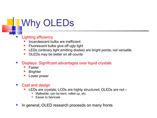
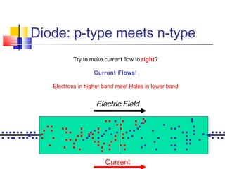
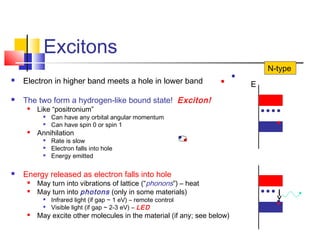
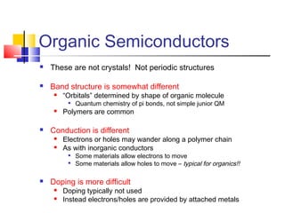
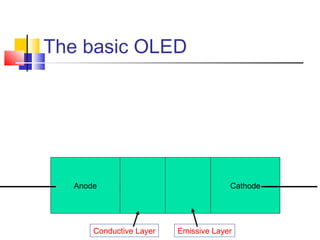
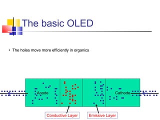
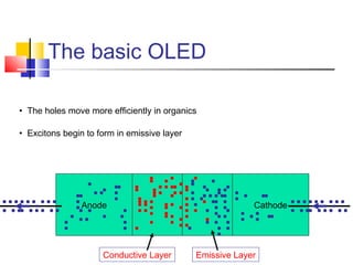
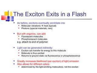
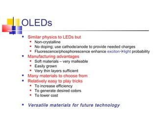
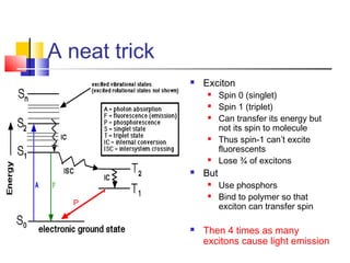
Organic Light Emitting Diodes
(OLEDs)
.
Why OLEDs
 Lighting efficiency
 Incandescent bulbs are inefficient
 Fluorescent bulbs give off ugly light
 LEDs (ordinary light emitting diodes) are bright points; not versatile
 OLEDs may be better on all counts
 Displays: Significant advantages over liquid crystals
 Faster
 Brighter
 Lower power
 Cost and design
 LEDs are crystals; LCDs are highly structured; OLEDs are not –

Malleable; can be bent, rolled up, etc.

Easier to fabricate
 In general, OLED research proceeds on many fronts
Plan of talk
 Light-Emitting Diode

Bands and Conduction

Semiconductor

Standard Diode

Light Emission
 Organic Light-Emitting Diode

Organic Semiconductors

Organic Diode

Light Emission
Electrons in a Lattice
 Atom has bound states
 Discrete energy levels
 Partially filled by electrons
 Periodic array of atoms
(cf. QM textbook)
 Effectively continuous
bands of energy levels
 Also partially filled
V(r)
r
E
V(x)
r
E
The Bands on Stage
E E E EE
Gap
No
Ga
p
Smal
l Gap
Insulator Conductor Semiconductor Doped Semiconductors
Doping – Add Impurities
N-type P-type
The Bands on Stage
E E E EE
Gap
No
Ga
p
Smal
l Gap
Insulator Conductor Semiconductor Doped Semiconductors
N-type P-type
Diode: p-type meets n-type
E
E
Diode: p-type meets n-type
E
E
Diode: p-type meets n-type
E
E
Diode: p-type meets n-type
E
E
Electric Field
Excess
Positive
Ions
Excess
Negative
Ions
Diode: p-type meets n-type
Electric Field
Try to make current flow to left?
Depletion Zone Grows
Diode: p-type meets n-type
Electric Field
Try to make current flow to right?
Current Flows!
Electrons in higher band meet Holes in lower band
Current
Excitons
 Electron in higher band meets a hole in lower band
 The two form a hydrogen-like bound state! Exciton!
 Like “positronium”

Can have any orbital angular momentum

Can have spin 0 or spin 1
 Annihilation

Rate is slow

Electron falls into hole

Energy emitted
 Energy released as electron falls into hole
 May turn into vibrations of lattice (“phonons”) – heat
 May turn into photons (only in some materials)

Infrared light (if gap ~ 1 eV) – remote control

Visible light (if gap ~ 2-3 eV) – LED
 May excite other molecules in the material (if any; see below)
E
N-type
Organic Semiconductors
 These are not crystals! Not periodic structures
 Band structure is somewhat different
 “Orbitals” determined by shape of organic molecule

Quantum chemistry of pi bonds, not simple junior QM
 Polymers are common
 Conduction is different
 Electrons or holes may wander along a polymer chain
 As with inorganic conductors

Some materials allow electrons to move

Some materials allow holes to move – typical for organics!!
 Doping is more difficult
 Doping typically not used
 Instead electrons/holes are provided by attached metals
The basic OLED
Anode Cathode
Conductive Layer Emissive Layer
The basic OLED
Anode Cathode
• The holes move more efficiently in organics
Conductive Layer Emissive Layer
The basic OLED
Anode Cathode
Conductive Layer Emissive Layer
• The holes move more efficiently in organics
• Excitons begin to form in emissive layer
The Exciton Exits in a Flash
 As before, excitons eventually annihilate into
 Molecular vibrations  heat (typical)
 Photons (special materials, rare)
 But with organics, can add
 Fluorescent molecules
 Phosphorescent molecules
e.g. attach to end of polymer
 Light can be generated indirectly:
 Exciton can transfer its energy to this molecule
 Molecule is thus excited
 Returns to ground state via fluorescence or phosphorescence
 Greatly increases likelihood (per exciton) of light emission
 Also allows for different colors
 determined by the light-emitting molecule(s), not the exciton
OLEDs
 Similar physics to LEDs but
 Non-crystalline
 No doping; use cathode/anode to provide needed charges
 Fluorescence/phosphorescence enhance excitonlight probability
 Manufacturing advantages
 Soft materials – very malleable
 Easily grown
 Very thin layers sufficient
 Many materials to choose from
 Relatively easy to play tricks
 To increase efficiency
 To generate desired colors
 To lower cost
 Versatile materials for future technology
Some references
 How Stuff Works
http://electronics.howstuffworks.com
 Craig Freudenrich, “How OLEDs work”
 Tom Harris, “How LEDs Work”
 Hyperphysics Website
http ://hyperphysics.phy-astr.gsu.edu/hbase/solids/pnjun.html
 “The P-N Junctions”, by R Nave
 Connexions Website
http://cnx.org
 “The Diode”, by Don Johnson
 Webster Howard, “Better Displays with Organic Films”
 Scientific American, pp 5-9, Feb 2004
 M.A. Baldo et al, “Highly efficient phosphorescent
emission from organic electroluminescent devices”
 Nature 395, 151-154 (10 September 1998)
 Various Wikipedia articles, classes, etc.
A neat trick
 Exciton
 Spin 0 (singlet)
 Spin 1 (triplet)
 Can transfer its energy but
not its spin to molecule
 Thus spin-1 can’t excite
fluorescents
 Lose ¾ of excitons
 But
 Use phosphors
 Bind to polymer so that
exciton can transfer spin
 Then 4 times as many
excitons cause light emission
P

Organic light emitting diodes

  • 1.
    Organic Light EmittingDiodes (OLEDs) .
  • 2.
    Why OLEDs  Lightingefficiency  Incandescent bulbs are inefficient  Fluorescent bulbs give off ugly light  LEDs (ordinary light emitting diodes) are bright points; not versatile  OLEDs may be better on all counts  Displays: Significant advantages over liquid crystals  Faster  Brighter  Lower power  Cost and design  LEDs are crystals; LCDs are highly structured; OLEDs are not –  Malleable; can be bent, rolled up, etc.  Easier to fabricate  In general, OLED research proceeds on many fronts
  • 3.
    Plan of talk Light-Emitting Diode  Bands and Conduction  Semiconductor  Standard Diode  Light Emission  Organic Light-Emitting Diode  Organic Semiconductors  Organic Diode  Light Emission
  • 4.
    Electrons in aLattice  Atom has bound states  Discrete energy levels  Partially filled by electrons  Periodic array of atoms (cf. QM textbook)  Effectively continuous bands of energy levels  Also partially filled V(r) r E V(x) r E
  • 5.
    The Bands onStage E E E EE Gap No Ga p Smal l Gap Insulator Conductor Semiconductor Doped Semiconductors
  • 6.
    Doping – AddImpurities N-type P-type
  • 7.
    The Bands onStage E E E EE Gap No Ga p Smal l Gap Insulator Conductor Semiconductor Doped Semiconductors N-type P-type
  • 8.
  • 9.
  • 10.
  • 11.
    Diode: p-type meetsn-type E E Electric Field Excess Positive Ions Excess Negative Ions
  • 12.
    Diode: p-type meetsn-type Electric Field Try to make current flow to left? Depletion Zone Grows
  • 13.
    Diode: p-type meetsn-type Electric Field Try to make current flow to right? Current Flows! Electrons in higher band meet Holes in lower band Current
  • 14.
    Excitons  Electron inhigher band meets a hole in lower band  The two form a hydrogen-like bound state! Exciton!  Like “positronium”  Can have any orbital angular momentum  Can have spin 0 or spin 1  Annihilation  Rate is slow  Electron falls into hole  Energy emitted  Energy released as electron falls into hole  May turn into vibrations of lattice (“phonons”) – heat  May turn into photons (only in some materials)  Infrared light (if gap ~ 1 eV) – remote control  Visible light (if gap ~ 2-3 eV) – LED  May excite other molecules in the material (if any; see below) E N-type
  • 15.
    Organic Semiconductors  Theseare not crystals! Not periodic structures  Band structure is somewhat different  “Orbitals” determined by shape of organic molecule  Quantum chemistry of pi bonds, not simple junior QM  Polymers are common  Conduction is different  Electrons or holes may wander along a polymer chain  As with inorganic conductors  Some materials allow electrons to move  Some materials allow holes to move – typical for organics!!  Doping is more difficult  Doping typically not used  Instead electrons/holes are provided by attached metals
  • 16.
    The basic OLED AnodeCathode Conductive Layer Emissive Layer
  • 17.
    The basic OLED AnodeCathode • The holes move more efficiently in organics Conductive Layer Emissive Layer
  • 18.
    The basic OLED AnodeCathode Conductive Layer Emissive Layer • The holes move more efficiently in organics • Excitons begin to form in emissive layer
  • 19.
    The Exciton Exitsin a Flash  As before, excitons eventually annihilate into  Molecular vibrations  heat (typical)  Photons (special materials, rare)  But with organics, can add  Fluorescent molecules  Phosphorescent molecules e.g. attach to end of polymer  Light can be generated indirectly:  Exciton can transfer its energy to this molecule  Molecule is thus excited  Returns to ground state via fluorescence or phosphorescence  Greatly increases likelihood (per exciton) of light emission  Also allows for different colors  determined by the light-emitting molecule(s), not the exciton
  • 20.
    OLEDs  Similar physicsto LEDs but  Non-crystalline  No doping; use cathode/anode to provide needed charges  Fluorescence/phosphorescence enhance excitonlight probability  Manufacturing advantages  Soft materials – very malleable  Easily grown  Very thin layers sufficient  Many materials to choose from  Relatively easy to play tricks  To increase efficiency  To generate desired colors  To lower cost  Versatile materials for future technology
  • 21.
    Some references  HowStuff Works http://electronics.howstuffworks.com  Craig Freudenrich, “How OLEDs work”  Tom Harris, “How LEDs Work”  Hyperphysics Website http ://hyperphysics.phy-astr.gsu.edu/hbase/solids/pnjun.html  “The P-N Junctions”, by R Nave  Connexions Website http://cnx.org  “The Diode”, by Don Johnson  Webster Howard, “Better Displays with Organic Films”  Scientific American, pp 5-9, Feb 2004  M.A. Baldo et al, “Highly efficient phosphorescent emission from organic electroluminescent devices”  Nature 395, 151-154 (10 September 1998)  Various Wikipedia articles, classes, etc.
  • 22.
    A neat trick Exciton  Spin 0 (singlet)  Spin 1 (triplet)  Can transfer its energy but not its spin to molecule  Thus spin-1 can’t excite fluorescents  Lose ¾ of excitons  But  Use phosphors  Bind to polymer so that exciton can transfer spin  Then 4 times as many excitons cause light emission P