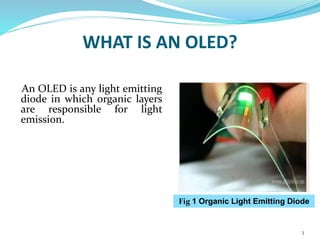
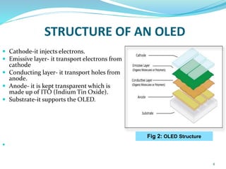
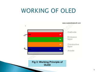
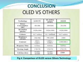
ORGANIC LIGHT EMITTING DIODE
(OLED)
PRATIM SARMA
B.sc 5th semester
Electronics Dept.
1
CONTENTS
 INTRODUCTION
 STRUCTURE OF AN OLED
 WORKING PRINCIPLE OF OLED
 TYPES OF OLED’S
 ADVANTAGES OF OLED
 DISADVANTAGES OF OLED
 APPLICATIONS OF OLED
 CONCLUSION
2
WHAT IS AN OLED?
An OLED is any light emitting
diode in which organic layers
are responsible for light
emission.
3
Fig 1 Organic Light Emitting Diode
STRUCTURE OF AN OLED
 Cathode-it injects electrons.
 Emissive layer- it transport electrons from
cathode
 Conducting layer- it transport holes from
anode.
 Anode- it is kept transparent which is
made up of ITO (Indium Tin Oxide).
 Substrate-it supports the OLED.

4
Fig 2: OLED Structure
HOW DO OLED’s Emit Light
 Electrons enter cathode
 Holes enter Anode
 Electrons enter Emissive layer
 Holes enter Conductive Layer
 Electrons and Holes Combine and They emitt Light.
5
6
Fig 3: Working Principle of
OLED
TYPES OF OLED’S
 Passive –Matrix OLED
 Active-Matrix OLED
 Transparent OLED
 Top-Emitting OLED
 Foldable OLED
 White OLED
7
ADVANTAGES
 Less power consumption
 Lower cost in future
 Flexible display
 Thin display
 Safer for environment.
8
DISADVANTAGES
 Lifespan
 Easy damageable
 Outdoor performance
 Complex fabrication methods
9
APPLICATIONS
 Mobile telephones
 Wall display
 Smart window
 Portable games
 Medical handheld devices
 Unbreakable display for school
 And many more that we cannot imagine even today
10
CONCLUSION
11
Fig 4: Comparison of OLED versus Others Technology
REFERENCES
 The OLED Handbook- Ron Mertens
 Basic Electronics-B.L. Theraja
 www.electronicshub.org
 www.slideshare.com
 www.explainthatstuff.com
12
13

Oled technology

  • 1.
    ORGANIC LIGHT EMITTINGDIODE (OLED) PRATIM SARMA B.sc 5th semester Electronics Dept. 1
  • 2.
    CONTENTS  INTRODUCTION  STRUCTUREOF AN OLED  WORKING PRINCIPLE OF OLED  TYPES OF OLED’S  ADVANTAGES OF OLED  DISADVANTAGES OF OLED  APPLICATIONS OF OLED  CONCLUSION 2
  • 3.
    WHAT IS ANOLED? An OLED is any light emitting diode in which organic layers are responsible for light emission. 3 Fig 1 Organic Light Emitting Diode
  • 4.
    STRUCTURE OF ANOLED  Cathode-it injects electrons.  Emissive layer- it transport electrons from cathode  Conducting layer- it transport holes from anode.  Anode- it is kept transparent which is made up of ITO (Indium Tin Oxide).  Substrate-it supports the OLED.  4 Fig 2: OLED Structure
  • 5.
    HOW DO OLED’sEmit Light  Electrons enter cathode  Holes enter Anode  Electrons enter Emissive layer  Holes enter Conductive Layer  Electrons and Holes Combine and They emitt Light. 5
  • 6.
    6 Fig 3: WorkingPrinciple of OLED
  • 7.
    TYPES OF OLED’S Passive –Matrix OLED  Active-Matrix OLED  Transparent OLED  Top-Emitting OLED  Foldable OLED  White OLED 7
  • 8.
    ADVANTAGES  Less powerconsumption  Lower cost in future  Flexible display  Thin display  Safer for environment. 8
  • 9.
    DISADVANTAGES  Lifespan  Easydamageable  Outdoor performance  Complex fabrication methods 9
  • 10.
    APPLICATIONS  Mobile telephones Wall display  Smart window  Portable games  Medical handheld devices  Unbreakable display for school  And many more that we cannot imagine even today 10
  • 11.
    CONCLUSION 11 Fig 4: Comparisonof OLED versus Others Technology
  • 12.
    REFERENCES  The OLEDHandbook- Ron Mertens  Basic Electronics-B.L. Theraja  www.electronicshub.org  www.slideshare.com  www.explainthatstuff.com 12
  • 13.