Download as PDF, PPTX

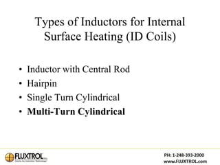
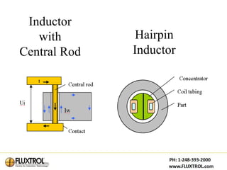
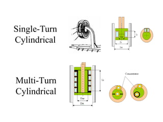
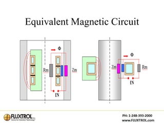

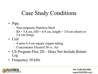
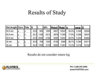
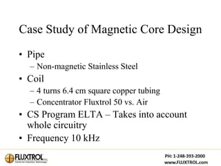
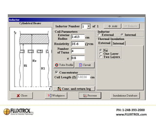
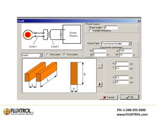
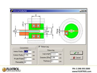
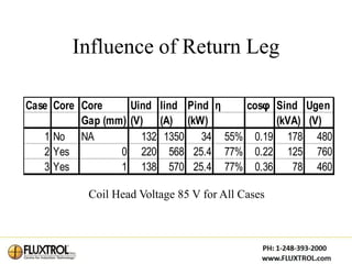

This document discusses the optimal design of internal induction coils for surface heating. It examines different coil designs like the inductor with central rod, hairpin, single-turn cylindrical, and multi-turn cylindrical coils. The study compares the performance of coils with and without magnetic cores and return legs. It finds that magnetic flux controllers with cores and poles drastically improve coil performance by increasing efficiency and power factor. While return legs only introduce small losses, they can cause significant voltage drops. Proper design of the magnetic core is essential for optimal coil induction heating performance.


