SlideShare a Scribd company logo
1 of 13
Download to read offline
Magnetic Flux Controllers in Induction
Heating and Melting
Robert Goldstein, Fluxtrol, Inc.
MAGNETIC FLUX CONTROLLERS are
materials other than the copper coil that are used
in induction systems to alter the flow of the mag-
netic field. Magnetic flux controllers used in
power supplying components are not considered
in this article.
Magnetic flux controllers have been in exis-
tence since the development of the induction
technique. Michael Faraday used two coils of
wire wrapped around an iron core in his experi-
mentsthat led toFaraday’s law of electromagnetic
induction, which states that the electromotive
force (emf) induced in a circuit is directly propor-
tional to the time rate of change of the magnetic
flux through the circuit. After the development
of the induction principle, magnetic flux control-
lers, in the form of stacks of laminated steel, found
widespread use in the development of transfor-
mers for more efficient transmission of energy
(Ref 1, 2).
Magnetic cores gained widespread use in the
transformer industry because they increased
the amount of magnetic flux produced with
the same alternating current. The higher the
magnetic flux, the higher the emf, which results
in an increase in energy transfer efficiency from
the primary winding to the secondary winding.
Similar to transformers, magnetic cores were
used on early furnaces for induction melting
(Ref 1, 2). The benefits of magnetic flux control-
lers vary depending on the application. For
induction heating, magnetic flux controllers can
provide favorable and unfavorable paths for mag-
netic flux to flow, resulting in increased heating in
desired areas and reduced the heating in undesir-
able areas, respectively. Magnetic flux controllers
are not used in every induction heating applica-
tion, but their use has increased (Ref 3, 4).
Magnetic Circuits in Induction
Applications
Induction heating applications are similar to
transformers with a short circuited secondary
winding. The primary winding of the circuit
is the induction coil and the secondary is the
workpiece. For both cases, there are three closed
loops: flow of current in the coil, flow of mag-
netic flux, and flow of current in the workpiece.
In most cases, the difference between induc-
tion heating applications and transformers is that
the magnetic circuit is open. The magnetic field
path includes not only the area with the control-
ler, but also the workpiece surface layer and the
air between the surface and controller, which
cannot be changed. Therefore, the reluctance of
the magnetic path only partially depends on the
magnetic permeability of the controller (Ref 3).
Reluctance is a term used in magnetics analo-
gous to resistance in electricity.
Figure 1 shows a diagram of the magnetic
circuit for a single-turn induction coil with a
magnetic flux concentrator heating a cylindrical
workpiece from the outside. The magnetic flux
in the system is equal to the ampere turns of
the coil divided by the reluctance of the magnetic
circuit. The reluctance of the magnetic circuit
consists of three basic components: the back path
for magnetic flux, the coupling gap, and the
workpiece. When a magnetic flux concentrator
is applied, it strongly reduces the reluctance of
the back path for the magnetic flux (Ref 3). All
induction heating systems can be described in
this way.
The benefits of a magnetic flux concentrator
on the electrical parameters for a given applica-
tion depends on the ratio of the reluctance of
the back path for magnetic flux to the overall
reluctance in the system. It is also possible to
break down basic system components into sub-
components to determine the most economical
use of magnetic flux controllers in a given appli-
cation. Other benefits of magnetic flux control-
lers, such as shielding areas from heating, can
also be understood by describing induction sys-
tems in this manner.
Role of Magnetic Flux Controllers
in Induction Systems
Magnetic flux controllers are powerful tools
in induction heating technology. In general,
two primary reasons to use magnetic flux con-
trollers in induction systems are to reduce and
increase magnetic fields in a given region.
Reducing magnetic fields is done by using
either soft-magnetic materials or electrically
conductive materials in a closed loop perpen-
dicular to the flow of the magnetic flux between
the coil and the desired lower field area. Soft-
magnetic materials improve induction coil
parameters, while highly conductive materials
have a negative effect. Soft-magnetic materials
are primarily used to increase magnetic fields.
The benefits of using magnetic flux control-
lers in an induction heating system include:
 Improvement of induction coil and process
efficiency
 Improvement of coil power factor
 Reduction in coil current
 Reduction in unintended heating of machine
components
 Reduction in undesired heating of areas of
the workpiece
ASM Handbook, Volume 4C, Induction Heating and Heat Treatment
V. Rudnev and G.E. Totten, editors
Copyright # 2014 ASM InternationalW
All rights reserved
www.asminternational.org
Fig. 1 Magnetic circuit in a single turn coil with
magnetic flux concentrator heating cylindrical
part from the outside: F = total. Source: Ref 3
Precise control of the magnetic field and
resulting heat pattern
 Improvement in efficiency of high-frequency
power supplying circuitry
 Reduction of external magnetic fields in
close proximity to the coil
In most applications, more than one of these
benefits usually occurs (Ref 3–7). Recently,
better understanding of the role magnetic flux
controllers in induction heating systems has been
obtained through comprehensive studies using
computer simulation and experiments, such as
those conducted at Fluxtrol, Inc. Results show
that a magnetic flux controller properly used
is typically beneficial in an induction heating
system (Ref 3). Magnetic flux controllers play
different roles in induction heating installations.
Depending on the application, they are referred
to as concentrators, controllers, diverters, cores,
impeders, yokes, shunts, and screens. The effects
of controllers in different types of induction heat-
ing applications are described here.
Materials for Magnetic
Flux Control
Two main categories of materials for mag-
netic flux control are electrically conductive
materials and magnetic materials. Electrically
conductive materials typically are used in the
form of shunts and screens to reduce external
magnetic fields.
Two main forms of magnetic materials are hard
and soft. The difference is the amount of flux den-
sity that remains after they are no longer exposed
to a magnetic field. Hard magnetic materials
retain a significant amount of the magnetic field,
while soft materials retain almost no magnetic
field when the source is turned off. Soft magnetic
materials are used almost exclusively as con-
centrators, controllers, diverters, cores, impeders,
yokes, shunts, and screens for magnetic flux con-
trol in induction systems.
Highly Conductive Materials
for Field Reduction
Highly conductive materials in the form of
closed loops are commonly used in induction
systems to reduce the level of magnetic fields
in certain areas. The effect on the distribution
of the magnetic field is described by Lenz’s
Law, which states an induced electromotive
force always produces a current whose mag-
netic field opposes the original change in
magnetic flux. This current creates a field of
reaction that influences the distribution of the
magnetic field, and increases both the reluc-
tance of the magnetic circuit and the current
in the coil to produce the same amount of heat
in the workpiece. These closed loops, com-
monly referred to as Faraday, or “robber” rings
carry high frequency currents, which result in
heating by Joule losses. The losses reduce the
efficiency of the system, and are not desirable.
Therefore, nonmagnetic materials with high
electrical conductivity are preferred for use as
Faraday rings. Copper is the most common
material used, but other materials, such as alu-
minum, are used due to cost and/or weight
considerations.
Soft Magnetic Materials for
Magnetic Flux Control
Soft magnetic materials most commonly used
in induction systems are laminations and soft
magnetic composites. Soft magnetic ferrites are
used occasionally in some high-frequency appli-
cations. The main requirements are that it should
have a relative magnetic permeability 1 and
should not have a good electrically conductive
path for strong eddy current generation.
Placing the material in the path of magnetic
flux lowers the reluctance of that part of the
magnetic circuit. Therefore, it requires less cur-
rent to drive the magnetic flux through that
part of the circuit, and a higher percentage of
flux flows in the magnetic material than would
flow in the same space containing only air.
However, this positive effect has some limita-
tions because the magnetic circuit is almost
always open.
For the same coil current, workpiece power
increases with increasing concentrator per-
meability very fast initially, then approaches
the threshold value asymptotically. At the
same time, losses in the induction coil often
increase slowly with increasing concentrator
permeability.
Computer simulation was used to demon-
strate the diminishing positive effect of very
high permeabilities in induction applications.
In a real induction heating application, the mag-
netic permeability of a magnetic flux controller
depends on magnetic flux density, frequency,
and temperature of the controller itself (not
the part it is heating). In the study, permeability
in the magnetic flux controller is considered to
be constant in the cross-section and at a fixed
value for each calculation. The study was not
conducted for a particular material, but is used
only to show the effect of conductor permeabil-
ity on induction coil parameters.
Figure 2 shows the effects of magnetic per-
meability on coil current and efficiency for
heating a flat plate using a single leg of an
inductor at frequencies of 3 and 10 kHz. Simi-
lar studies show that in most induction heating
applications, the threshold value for workpiece
power occurs when concentrator permeability
is 100. In high-frequency induction heating
applications, the threshold value occurs at
lower levels of permeability. Therefore, incre-
asing permeability to higher values will not
improve coil parameters significantly (Ref 3).
In some cases, use of materials with higher
than optimal magnetic permeability reduces
induction coil lifetimes without any benefits
(Ref 3, 8, 9).
Other important properties of soft magnetic
materials, such as good saturation flux density,
stable mechanical properties, low magnetic
losses, chemical resistance, and resistance to
elevated temperature depend on the application.
Laminations are commonly made of coated
thin sheets of silicon electrical steel with 3 or
4% silicon. The laminates are cut (by water
jet, laser, CNC, and electrical discharge machin-
ing) or stamped to the required shape for use in
induction coils.
For induction coils, multiple laminations are
stacked between mechanical supports called
keepers (Fig. 3). The large lamination cross
section is oriented so it is in the plane of the
flow of the magnetic field; intense eddy current
heating occurs if it is not in the plane.
Lamination thickness varies based on fre-
quency used to limit eddy-current losses from
the in-plane magnetic field. The lamination coat-
ing prevents an electrical connection between
individual laminations. In line-frequency appli-
cations, individual laminations are typically
between 0.020 to 0.040 in. (0.5 to 1 mm) thick.
Laminations can be as thin as 0.002 in. in appli-
cations using higher frequencies.
Laminations have very high magnetic perme-
ability and saturation flux density. They also
have high temperature resistance limited pri-
marily by the coating. The primary drawbacks
of laminations are intense heating in 3-D mag-
netic fields and limited frequency range (up to
about 30 kHz).
Soft Magnetic Composites consist of a
soft-magnetic component (typically iron and
iron-base alloy powder metal) and a dielectric
component (usually an organic polymer binder).
The soft-magnetic component provides a favor-
able path in which the magnetic field can flow.
The dielectric component electrically insulates
magnetic particles from each other to limit eddy
current losses.
Two main forms of soft-magnetic composites
are machinable and formable. Machinable
materials are commonly produced via powder
metallurgy compaction techniques and heat
treated to improve magnetic and mechanical
properties. Machining soft-magnetic compo-
sites is easier than machining laminations.
The composites are applied on induction coils
using an adhesive and mechanical supports
(Fig. 4).
Machinable-soft magnetic composites have
good magnetic permeability and saturation flux
density, as well as good temperature resistance,
which is limited primarily by the polymer
binder. Unlike laminations, soft-magnetic com-
posites can be tailored to work in the entire
range of frequencies for induction heating and
melting, and perform well in 3-D magnetic
fields (Ref 3–7).
Formable soft-magnetic composites are shaped
around the induction-coil surfaces, held in place
mechanically, and cured in an oven, which fixes
their shape. Magnetic properties of formable
soft magnetic composites are not as favorable as
those of machinable composites, and are used in
634 / Equipment
instances of irregular geometries and use of a
machined material is difficult.
Figure 5 shows relative magnetic permeabil-
ity versus magnetic field strength of some com-
mon soft-magnetic composites (Ref 4). Their
diverse properties offer the opportunity for fine
control using different materials on the same
induction coil.
Design Guidelines for Using
Magnetic Flux Controllers on
Induction Coils
The decision of where to use a magnetic flux
controller depends strongly on the shape of the
induction heating coil. Many induction coils are
hybrids and have components made of more
than one of the basic coil types. Therefore, it
is important to understand how magnetic flux
flows and how it is affected by a magnetic flux
controller to properly apply it on more complex
induction coils.
Effects of Magnetic Flux Controllers
on Common Coil Styles
Outer Diameter (OD) Coils. The basic
magnetic circuit for an OD coil (Fig. 1) was
described previously. Computer simulation is
used to visualize and quantify the effects of
a magnetic flux controller on an induction heat-
ing system (Ref 3–7). Figure 6 shows magnetic
field lines and current density in a single-turn
OD coil for heating a cylindrical copper work-
piece with and without the use of a magnetic
flux controller. The same voltage (similar value
of magnetic flux) is applied to each coil. The
process was simulated using Cedrat Technolo-
gies Flux 2D software. A copper workpiece
was used so current density values in the induc-
tion coil and workpiece were similar to make
visualization of the effects easier.
The magnetic field is distributed in a smaller
area for the coil with the magnetic flux control-
ler, and the resulting current density in the part
is concentrated under the coil heating face.
Nearly all of the power induced into the part
is useful, and leads to an increase in tempera-
ture in the desired heating area. Nearly all of
the current in the coil with the magnetic flux
controller flows on the heating face.
In the coil without a magnetic flux controller, a
significant portion of the current flows in areas
outside of the heating face, which does not help
heating the part, but instead, draws additional
power from the power supply. A significant por-
tion of current in the coil flows up the sides of the
turn and around the back; this current is not use-
ful and only leads to additional losses in the coil,
busswork, and matching components.
The reduction in current in the coil and con-
centration of power under the heating face is
called the concentrator effect (Ref 3, 10, 11),
and can be explained by considering the system
from a magnetic circuit point of view (see
Fig. 1). The concentrator effect is a result of
the magnetic flux controller lowering the
Fig. 2 Effect of magnetic permeability on coil current (a) and efficiency (b); curves generated from computer simulation of heating a flat plate using a single leg of an inductor;
50 kW in the part under the coil face. Source: Ref 3.
Fig. 3 Induction coil with laminations stacked bet-
ween mechanical supports. Courtesy of Tucker
Induction.
Fig. 4 Induction coil with soft magnetic composites.
Source: Ref 3
Magnetic Flux Controllers in Induction Heating and Melting / 635
reluctance of this portion of the magnetic cir-
cuit and reducing the need for current in this
area of the induction coil to drive the magnetic
flux around the back path.
The primary benefits of magnetic flux con-
trollers on OD induction coils are:
 Higher efficiency
 Improved heat pattern control (ability to heat
fillets, not overheat shoulders, obtain sharper
transition zones, etc.)
 Better use of power in the workpiece (energy
savings)
 Reduction in the induction coil current
(reduced losses in power supplying circuitry)
 Reduction in heating of unintended areas of
the part
 Reduction in heating of machine/structural
components
 Reduction in external magnetic fields
The aspect ratio of the induction coil must be
considered to determine the impact of a mag-
netic flux controller on an OD coil. Two key
variables are the ratio of coil length to diameter,
and the ratio of the coupling gap to the length
of the coil. Magnetic flux controllers are most
benefitial when the length-to-diameter ratio and
coupling gap-to-length ratio are small. The effects
of the magnetic flux controller are reduced as
these ratios increase. For very large coupling gaps
relative to coil length, a magnetic flux controller
can result in lower electrical efficiency.
Inner Diameter (ID) Coils. The basic mag-
netic circuit for an ID coil is shown in Fig. 7.
The return path for magnetic flux is on the
inside of the coil. Power density in the workpiece
is proportional to the magnetic flux density
squared, and flux density is magnetic flux divided
by the cross-sectional area through which it is
flowing. The magnetic impedance of an area is
directly proportional to the length of the region
and inversely proportional to the cross-sectional
area. Therefore, the magnetic resistance (Rm)
component is a higher percentage of the total
reluctance on an ID coil than it is on an OD coil.
Due to the larger influence of Rm, the effect
of a magnetic flux controller on ID coils is much
larger than on OD coils (Ref 3, 12). Benefits of
magnetic flux controllers on ID induction coils
include:
 Improved coil efficiency (energy savings)
 Better use of power in the workpiece (energy
savings)
 Reduction in induction-coil current (reduced
losses in power supplying circuitry, coil leads)
 Reduction in heating of unintended areas of
the part
 Improved heat pattern control
Magnetic flux controllers significantly improve
nearly all ID coils. To determine the impact
Fig. 5 Magnetic permeability of some Fluxtrol soft-magnetic composite materials as a function of magnetic field
strength.
Color Shade Results
Quantity : |Current density| A/(square mm)
Phase (Deg): 0
Scale / Color
0 / 14.8125
14.8125 / 29.625
29.625 / 44.4375
44.4375 / 59.25
59.25 / 74.0625
74.0625 / 88.875
88.875 / 103.6875
103.6875 / 118.5
118.5 / 133.3125
133.3125 / 148.125
148.125 / 162.9375
162.9375 / 177.75
177.75 / 192.5625
192.5625 / 207.375
207.375 / 222.1875
222.1875 / 237
Fig. 6 Magnetic field lines and current density for a single-turn OD coil with (left) and without (right) a magnetic flux
controller. Courtesy of Fluxtrol, Inc. Fig. 7 Magnetic circuit for ID coil. Source: Ref 3
636 / Equipment
on the coil, it is necessary to consider the coil
aspect ratio. Similar to OD coils, two key vari-
ables are the coil length-to-diameter ratio and
the coupling gap-coil length ratio. Unlike OD
coils, aspect ratios that benefit most from a
magnetic controller are inverted. Magnetic flux
controllers provide the greatest benefit when the
two ratios are larger.
Linear Coils. Three basic classes of linear
induction coils are:
 Coils with return current on the opposite
side of the part (e.g., single-shot coils, oval
coils, channel coils)
 Coils with one primary heating leg and
distributed return on the same side of the
part (vertical loop, split-n-return coils)
 Coils with two active heating directions
and return on the same side of the part
(hairpin)
The difference between linear induction coils
and cylindrical coils is there is no natural flux
concentrating/de-concentrating effect from the
change in radius in linear coils. Therefore, the
only other electromagnetic effects present are
the proximity effect between coil and work-
piece and the proximity effect between the coil
turns themselves in the case where the return is
on the same side of the part.
A hairpin inductor (magnetic circuit shown
in Fig. 8) is used to illustrate the concept of a
magnetic circuit for linear coils. If the coil legs
are the same size and part properties under each
leg are the same, each leg produces one half of
the magnetic flux in the system. Magnetic flux
flows around the legs of each turn. In the region
between the two turns, magnetic flux from each
turn are additive, and the all magnetic flux from
the system flows through this area. At the same
time, the cross-section through which the mag-
netic flux must flow is smaller than the areas
of the back path for magnetic flux. Thus, the
Rm value is high on hairpin coils, and the bulk
of Rm resides in the region between the two
turns (Ref 3).
This phenomenon also occurs in other types
of linear inductors (e.g., vertical loop, split-n-
return) where the return is on the same side
of the inductor; the bulk of Rm resides in the
area between the turns that are in the opposite
direction. Use of a magnetic flux controller
in this area is very beneficial. The benefit is
greatest for aspect ratios where the distance
between turns relative to the coupling gap is
small. The benefit is less when the heat face
is long and the return is on the opposite side
of the part.
Cooling of Magnetic Flux
Controllers
The service life of induction heating coils
with magnetic flux controllers varies from days
to years. Cooling the magnetic flux controller
minimizes mechanical damage and increases
service life.
Heat Sources in Magnetic Flux Control-
lers. All magnetic flux controllers generate
and absorb heat when exposed to an alternating
magnetic field. The amount of heat depends
on induction system parameters, induction coil
and part geometry, magnetic flux controller
material, part temperature, and the atmosphere
surrounding the coil.
Highly conductive nonmagnetic materials are
heated by eddy currents, radiation and conduc-
tion from the hot part, and convection from
the hot environment. The main heat source is
from eddy currents. Because Faraday rings use
the eddy-current reaction field, the primary
ways to reduce losses is to use low-resistivity
materials and increase the length of the shield-
ing face.
Soft-magnetic materials are heated by eddy
currents, heat from thermal sources, hysteresis
losses, and sometimes by conductive heat trans-
fer from the copper coil. Unlike highly conduc-
tive nonmagnetic materials, shielding in soft-
magnetic materials is by concentration of fields
of reaction rather than by reduction of the fields.
Therefore, soft-magnetic materials are segmented
perpendicular to the plane of the magnetic field
at a small fraction of reference depth to minimize
eddy currents.
The electrical resistivities of laminations
are similar to those of steels, so individual lam-
ination thickness should be between 0.002 to
0.040 in. depending on frequency. With proper
lamination thickness, eddy current losses in
2-D magnetic fields make up a small portion
of the heat that needs to be removed. In 3-D
magnetic fields, eddy current losses grow rapidly
in laminations and are larger than the other heat
sources (Ref 3).
Soft-magnetic composites typically have
electrical resistivities several orders of mag-
nitude higher than those for laminations. In
general, composites that will be used in higher
frequency applications should have higher
electrical resistivities. Therefore, the allowable
thickness of soft-magnetic composites is much
larger, enabling fabrication of the concentrator
from one or only a few components. Global
eddy current losses in soft-magnetic composites
generally make up a small fraction of the total
heat (Ref 3).
For soft-magnetic composites, besides global
eddy current losses, there are also eddy currents
in the individual magnetic particles. Similar to
eddy currents in larger bodies, losses in individ-
ual particles are controlled by particle size and
composition. Smaller particles are typically
used for higher frequencies. In most induction
applications, eddy current losses in individual
particles make up only a small portion of the
total heat (Ref 3).
When the correct magnetic flux controller is
used, hysteresis losses make up the largest com-
ponent of heat that must be removed. Hysteresis
losses are due to internal friction of magnetic
domains as they reorient in the presence of an
alternating magnetic field.
A hysteresis loop is used to characterize mag-
netic hysteresis for a given magnetic material
(Fig. 9). Key points on the curve are saturation
flux density, remanence, and coercive force. Sat-
uration flux density is the threshold value for
the magnetization of the material. Remanence
is the magnetism that remains after removingFig. 8 Magnetic circuit for a hairpin inductor coil. Source: Ref 3.
Magnetic Flux Controllers in Induction Heating and Melting / 637
the source of the magnetic field. Coercive force
is a measure of how much magnetic field must
be applied in the opposite direction to remove
the remanence.
Losses in a magnetic material due to hystere-
sis are proportional to the product of the area of
the hysteresis loop and the frequency. For good
soft-magnetic materials, the hysteresis loop
should be as narrow as possible. Minimizing
hysteresis losses is accomplished through alloy-
ing elements and by stress relieving the mate-
rial (Ref 3).
Heat Removal in Magnetic Flux Control-
lers. The cooling method depends on the
type of magnetic flux controller used and the
process environment. Power density losses in
Faraday rings are higher than in soft-magnetic
materials. However, removing this heat is eas-
ier due to the nature of the materials. Depend-
ing on the magnitude of eddy current losses,
Faraday rings can be cooled using internal
water cooling, free convection, and conduction
to a large structure.
Losses in soft-magnetic materials (approxi-
mately directly proportional to frequency) are
small compared with those in the copper coil,
which are usually proportional to the square root
of frequency. For low frequencies, the ratio
between copper losses and soft magnetic losses
is large. It is smaller at higher frequencies, but
copper losses are still the dominant factor in
total coil losses below several MHz.
For soft-magnetic materials operating at low
frequencies or low power densities, cooling by
free convection is sufficient to maintain a satis-
factory temperature provided the atmosphere is at
a temperature low enough to remove heat and the
magnetic core is not continuously exposed to
direct radiation from a hot part.
For medium frequencies and power densities,
the most common method to remove heat is con-
duction to the water-cooled copper (Fig. 10).
A thermally conductive adhesive is placed
between the soft-magnetic material and copper
tubing to facilitate heat removal. Desirable
thermal conductivities of laminations and soft-
magnetic composites are 15 to 100 times
lower than that for copper, and the thermal con-
ductivity of adhesives is even lower. Adhesive
layer thickness, consistency of gap filling,
and adhesive thermal conductivity each play a
critical role in heat removal from the magnetic
flux controller. The use of a 0.010-in. (0.25-mm)
layer of an epoxy adhesive (1 W/mK thermal
conductivity) with Fluxtrol materials is suffi-
cient for heat removal in most cases (Ref 4).
In instances of heavy loading, a supplemental
water-cooling plate applied to the backside
of the magnetic flux controller increases heat
extraction.
Direct water cooling could be required in appli-
cations involving very heavy loading. Cooling
methods include water channels in the concentra-
tor (for soft-magnetic composite only, Fig. 11),
supplemental water drizzle and quench head for
quench-in-place applications. A coating on water
cooling channels is recommended when using
direct water cooling of magnetic flux controllers
to prevent water cooling-system contamination.
Computer simulation shows that Fluxtrol 100
material can withstand continuous operation at
a magnetic flux density of 1 T, a frequency of
1 kHz, and direct exposure to radiation from a
1200 
C (2190 
F) part using direct water cooling
(Fig. 12).
Fig. 11 Soft magnetic composite material with channels for direct water cooling. Source: Ref 4
Fig. 10 The most common method to remove heat from a magnetic flux controller is by conduction to the water-
cooled copper coil. Source: Ref 3
Fig. 9 Hysteresis loop for magnetic materials. Source: Ref 3
638 / Equipment
Determining the Thickness of Soft
Magnetic Material
The amount of soft-magnetic material
required is determined by considering magnetic
flux density, mechanical strength, and physical
space available for the application. Magnetic
flux density is important because both magnetic
permeability and magnetic losses are dependent
on it. Magnetic flux density should not exceed
the saturation flux density of the magnetic con-
troller unless there is limited available space
and only partial shielding is required.
To determine magnetic loading, it is neces-
sary to determine the magnetic flux density B
in the magnetic material. For a long solenoid,
it can be determined from Eq 1 if the magnitude
of voltage on the coil head is known, or from
Eq 2 if the magnitude of the coil current is
known. In an electrical circuit, the magnetic
permeability of the material is a function of
magnetic flux density:
B ¼
U
oSN
(Eq 1)
B ¼
IN
l
(Eq 2)
where B is magnetic flux density, U is coil volt-
age, o is angular frequency, S is cross-sectional
area, N is number of turns, m is magnetic per-
meability, and l is length.
For most other coil styles, Eq 1 and 2 can
provide a rough estimate of flux density. Eq 1
is better for ID coils. Computer simulation pro-
vides the best information.
Magnetic Flux Control in Induction
Melting Systems
Three types of induction melting systems are
channel-type, crucible-type, and cold crucible.
Only the role of magnetic flux controllers in
an induction melting system is discussed here.
Details of each type of induction melting sys-
tem are discussed elsewhere in this Volume.
Channel Type Furnaces
Channel melting furnaces are similar to either
a transformer or an ID coil (Fig. 13). They should
always have a magnetic flux controller or better
system efficiency. Channel furnaces operate at
low frequencies and are used primarily to pro-
duce large volumes of metal. For this reason,
laminations are the material of choice due to
lower cost and availability in large sizes.
Crucible Type Furnaces
Crucible type furnaces consist of a solenoid
induction coil and a ceramic refractory or con-
ductive (graphite or metal) crucible. Magnetic
flux controllers are used on these furnaces pri-
marily to reduce external magnetic fields, which
can cause heating of the equipment structure, or
can necessitate a very large footprint due to occu-
pational safety limits for human exposure to
electromagnetic fields.
Large Low-Frequency Melting Furnaces.
Faraday rings and shunts are used in many large
furnaces; shunts are used on the OD of the
induction coil and a combination of Faraday
rings and counterwound turns are used on the
top and bottom of the coil. A crucible melting
furnace is shown in Fig. 14. The design is typical
of low-frequency (tens to hundreds of Hertz) fur-
naces used to melt large volumes of metal.
Shunts used in these furnaces generally are
silicon steel laminations contained in a metal
support structure. Silicon-steel shunts work
well on the back of the induction coil because
the field is regular, in one direction, and of a
simple geometry. Shunt assemblies with lami-
nation shunts are less expensive than alternative
materials such as soft-magnetic composites for
large low-frequency furnaces.
Incorporating laminations on the top and bot-
tom of the induction coil is more difficult,
which is why a combination of counterwound
turns and/or Faraday rings is used to reduce
the level of magnetic fields in this area. These
methods effectively control external fields, but
reduce coil efficiency.
Fig. 12 Computer simulation of heat removal from soft-magnetic material exposed to a magnetic flux density of 1 T,
a frequency of 1 kHz, and a 1200 
C part by direct water cooling. Source: Ref 4
Fig. 13 Schematic of channel-type induction melting
furnace. Source: Ref 13
Fig. 14 Sketch of induction crucible-type (coreless)
melting furnace. Source: Ref 2
Magnetic Flux Controllers in Induction Heating and Melting / 639
An alternative method is to use a soft-magnetic
composite ring on the top of the induction coil
backed by a Faraday ring. The composite strongly
reduces the level of magnetic field to which the
Faraday ring is exposed with lower losses than
using counterwound turns. Losses of this type of
assembly are much lower while providing the
same level of shielding. A drawback of this
approach is higher initial cost. Capital versus
operating costs should be considered when choos-
ing between top and bottom shielding.
Medium-Size Medium-Frequency Melting
Furnaces. Magnetic flux controllers are used
for the same purposes on 1 to 10-kHz frequency
medium-size furnaces as for larger ones, but
different materials are used. Many of these fur-
naces operate in a controlled atmosphere, where
magnetic flux controllers are more important
than in open air furnaces. The controllers could
be used to shield the chamber from heating.
Furnace size must be larger without the use of
magnetic flux controllers, increasing the capital
cost of the installation.
Lamination thickness decreases with increas-
ing frequency making them more difficult to
work with. Also, shount pack structural materials
heat up more at higher frequencies, resulting is
an increased cost of using laminate shunt packs.
Due to these factors, the use of soft-magnetic
composites is becoming more popular for
medium-size melting furnaces. Figure 15 shows
a medium-size melting coil with a Fluxtrol 100
soft-magnetic composite. This makes it possible
to incorporate magnetic poles on the top and
bottom of the induction coil, so it is not neces-
sary to counterwind the upper and lower turns
or use a Faraday ring. Therefore, the entire
length of the induction coil works together to
create the internal magnetic field.
Another benefit of magnetic flux controllers
in these furnaces is when multiple melting pots
are placed in close proximity to each other. The
furnaces can be controlled using either one
power supply or multiple power supplies. How-
ever, the magnetic fields of different pots inter-
act if they are placed too close to one another.
This phenomenon is called cross-talking, and it
can cause nonuniform melting pot performance.
Magnetic flux controllers greatly reduces the
amount of cross-talking.
Cold-Crucible Melting Furnaces
In cold-crucible furnaces, a water-cooled seg-
mented copper ring is placed between the
induction coil and the melt. Magnetic flux flows
through the slots of the cold crucible and heats
the melt. Water-cooled Faraday rings are often
used on the bottom of the furnace. A metal skull
typically forms between the melt and the copper
components, which creates a barrier that prevents
contamination of the melt by impurities.
These furnaces are less efficient than coreless
melting furnaces due to electrical losses in
the segmented copper ring, the lower Faraday
Fig. 15 Medium-sized melting coil with soft-
magnetic shunts. Courtesy of Fluxtrol, Inc
Traditional design
PDmax = 216 MW/m3
Color Shade Results
Quantity : Power density W/(cubic m)
Phase (Deg): 0
Scale / Color
0 / 13.50879E6
3.50879E6 / 27.01758E6
27.01758E6 / 40.52636E6
40.52636E6 / 54.03515E6
54.03515E6 / 67.54394E6
67.54394E6 / 81.05274E6
81.05274E6 / 94.56152E6
94.56152E6 / 108.0703E6
108.0703E6 / 121.57909E6
121.57909E6 / 135.08789E6
135.08789E6 / 148.59667E6
148.59667E6 / 162.10546E6
162.10546E6 / 175.61426E6
175.61426E6 / 189.12304E6
189.12304E6 / 202.63182E6
202.63182E6 / 216.14061E6
Modified design
PDmax = 279 MW/m3
Color Shade Results
Quantity : Power density W/(cubic m)
Phase (Deg): 0
Scale / Color
0 / 17.47247E6
17.47247E6 / 34.94494E6
34.94494E6 / 52.41741E6
52.41741E6 / 69.88988E6
69.88988E6 / 87.36234E6
87.36234E6 / 104.83482E6
104.83482E6 / 122.30729E6
122.30729E6 / 139.77976E6
139.77976E6 / 157.25224E6
157.25224E6 / 174.7247E6
174.7247E6 / 192.19717E6
192.19717E6 / 209.66965E6
209.66965E6 / 227.14211E6
227.14211E6 / 244.61459E6
244.61459E6 / 262.08706E6
262.08706E6 / 279.55952E6
Fig. 16 Comparison of power density in the melt charge derived from a 2-D simulation using Flux 2D software: (a)
traditional induction coil design with laminate shunts, and (b) modified design with a soft-magnetic
composite controller with top and bottom shunts. Source: Ref 14
640 / Equipment
ring, and thermal losses of the melt to the water-
cooled copper components. Therefore, cold-
crucible melting furnaces are typically used only
in the production of metals that are highly reactive
when molten or that require very low impurities.
Cold-crucible processes almost always are carried
out in a controlled atmosphere.
Magnetic flux controllers improve the effi-
ciency of cold-crucible furnaces. Similar to other
controlled-atmospheremelting applications,mag-
netic flux controllers are used on the OD of the
induction coil to shield the chamber from heating.
Additional improvements are achieved by
using magnetic poles on the top and bottom of
the induction coil to reduce the losses associated
with the Faraday rings on the top and bottom
of the cold crucible. Studies show up to 50%
improvement in induction coil efficiency using
an induction coil with soft-magnetic composite
top and bottom poles compared with a standard
coil design (Fig. 16, 17) (Ref 14).
Magnetic Flux Control in
Mass-Heating Applications
The role of magnetic flux controllers in an
induction mass-heating system depends on the
application. Of the many types of induction
mass-heating installations, the largest applica-
tion is heating component part prior to a shap-
ing operation, such as forging, forming, and
rolling. The role of magnetic flux controllers
whole-body and local area mass-heating appli-
cations is discussed here. Detailed discussion
of these types of installations are presented
elsewhere in this Handbook.
Whole-Body Mass Heating
Workpieces are large in most whole-body
mass-heating applications, and the part passes
through the induction coil. Part shape and induc-
tion coil length are the primary determinants of
the type of magnetic flux controller used in these
systems.
Long solenoids are used for long cylindrical
or tubular body workpieces. Soft-magnetic con-
trollers do not provide significant benefits for
long solenoids (length = several times the diam-
eter). Therefore, several induction coils are
used to bring the billet up to the desired temper-
ature distribution. In these installations, Fara-
day rings at the end of the coils are the only
magnetic flux controllers used (Fig. 18). They
perform two functions: shielding mechanical
handling rolls from heating and preventing
cross-talking among multiple coils used in the
billet-heating line.
For rectangular workpieces, the benefits of a
magnetic flux controller depend upon the aspect
ratio of the cross-section to be heated. For
square and nearly square parts, guidelines for
magnetic flux controller and coil selection are
similar to those for cylindrical and tubular
parts. Magnetic flux controllers play a greater
role for rectangular parts with one dimension
significantly larger than the other (e.g., slabs,
sheet, strip). In this case, both longitudinal and
transverse flux heating methods are used.
Longitudinal coils generate a uniform tem-
perature in the cross-section. Soft-magnetic
materials are beneficial when the length of the
induction coil is small relative to the perimeter
of the coil inside cross-section.
Soft-magnetic materials should be used on
transverse flux heating coils (Ref 3, 10, 15).
Material selection depends on the frequency.
Silicon steel laminations are used for low fre-
quencies, and soft magnetic composites are
used for middle and higher frequencies. Soft-
magnetic composites are also used near the
ends of low frequency transverse flux coils
where 3-D magnetic fields are present.
Local Area Mass Heating
In many cases, it is desirable to heat only a
portion of the component for forming. Local
area mass heating can be achieved using both
static and continuous heating arrangements.
For static heating, both single-turn and multi-
turn induction coils are used, where the coil l is
comparable to the coil diameter. Soft-magnetic
controllers applied to the induction coil improves
temperature distribution and coil efficiency due to
better use of power in the workpiece together with
reduced coil current demand.
Continuous heating applications use a chan-
nel coil, which can be one turn to heat fasten-
ers, for example (Fig. 19) or several turns as
in a bar end heater (Fig. 20). Soft-magnetic
controllers help significantly in both cases.
For single-turn channel coils, use of soft-
magnetic material reduces the power required
to heat the desired area of the part by 20 to
50% (Ref 3, 4). Soft-magnetic composites are
the material of choice because these applica-
tions usually operate at 10 kHz or higher.
Fluxtrol Design
Ptotal
(kW)
Ptotal
(kW)
Pleads Pmelt Pcoil Pcrucible I(A)
122.5 6% 47% 15.5% 31% 1600
Traditional Coil Design
Pleads Pmelt Pcoil Pcrucible I(A)
135 6.5% 31% 21% 41.5% 1900
Fig. 17 Comparison of integral power values for traditional induction coil design with laminate shunts and a Fluxtrol-designed coil with soft-magnetic composite controller with
top and bottom shunts. Source: Ref 14
Fig. 18 Billet-heating coil with Faraday rings on both
ends. Courtesy of Pillar Induction, Inc.
Magnetic Flux Controllers in Induction Heating and Melting / 641
The effect of soft-magnetic materials on
channel coils with multiple turns for heating
longer sections is not as strong as for shorter
single-turn coils; energy savings is typically
between 5 and 20% (Ref 3, 4).
Magnetic Flux Control in Induction
Tube-Welding Applications
Induction tube welding is a major application
of induction heating, used in high volume pro-
duction of carbon-steel tubes. It is also used to
produce stainless steel, copper, and aluminum
tubing. Magnetic flux controllers play a crucial
role in tube-welding lines, both in the welding
process and post weld heat treatment.
Magnetic Flux Controllers for
Continuous Induction Tube Welding
In an induction tube welding process, steel
strip is rolled into the form of a tube and passed
through a cylindrical induction coil where the
strip edges are heated. The strip passes through
a final set of rollers that close the profile of the
tube and welding occurs. Induction welding
systems for steel tubing operate at high fre-
quencies (100À500 kHz) and high power (in
the range of 100 kW to a few MWs).
Figure 21 shows a schematic of current flow
in the tube in a typical induction welding appli-
cation. The induction coil induces a current that
flows around the tube OD under the face of the
induction coil. When the current reaches the open
edge of the tube, it turns to close the current loop.
Three options for the current to flow are:
1. Along the edges of the steel strip toward the
rolls, connecting at the weld apex and return-
ing back on the opposite edge of the tube
2. Along the edges away from the V-shape
groove, returning on the tube OD of the tube
farther up the line
3. Along the tube ID
The first current path is the most desirable
one, the second path is somewhat useful, and
the third path is undesirable. In induction
welding applications, a soft-magnetic material
is placed inside the tube to reduce heating
along the ID of the tube and to enhance current
flow along the tube edges toward the V
groove. The soft-magnetic material on the tube
ID of the tube is referred to as an impeder,
because it impedes current flow along the
tube ID.
Impeders are made of soft magnetic ferrites
encased in a fiberglass tube with water cooling.
The tube protects the ferrite from metal spume
and provides mechanical support for the brittle
ferrites. The tube also keeps the ferrites in place
as they often fracture in production due to ther-
mal shock. Figure 22 shows some typical impe-
ders used in the welding industry. For large pipe
Fig. 20 Continuous bar-end heater with magnetic flux concentrator. Courtesy of Fluxtrol, Inc.
Fig. 19 Channel coil for fastener heating. Courtesy of
Fluxtrol, Inc.
Fig. 21 Schematic of a continuous high-frequency induction longitudinal seam tube-welding system. Source: Ref 13
Fig. 22 Impeders for small-tube welding; used for
current flow along the tube ID. Source: Ref 16
642 / Equipment
welding systems, the impeder consists of multi-
ple impeders assembled together, referred to as
a cluster impeder (Fig. 23).
Ferrites are the material of choice in most
tube-welding applications due to their low cost,
high magnetic permeability at lower flux densi-
ties, and low losses at high frequencies. The
drawbacks of ferrites are low-saturation mag-
netic flux density, sensitivity to thermal shock,
and sensitivity of magnetic properties to tem-
perature change.
The life of ferrites in the case of small tubes
ranges from several hours to a week. The mag-
netic flux density in the impeder core is higher
due to the smaller cross-section inside the tube,
and ferrites become saturated. In some instances
of short impeder life, ferrites have been replaced
with Fluxtrol 75 soft-magnetic composite, result-
ing in 10 to 30% energy savings and increased
life (Ref 17).
The efficiency of tube welding systems is
improved using an external magnetic bridge
(Ref 18). A soft-magnetic composite material
placed above the tube opening helps increase
current flow along the weld “V” and helps
balance heating of the top and bottom edges
of the tube wall (Fig. 24). In some applications,
the benefits of using an external magnetic
bridge are 20 to 30% energy savings and
improved weld quality. System improvements
from using a magnetic bridge depend on the
configuration of the weld rolls. To achieve sig-
nificant benefits, the magnetic bridge must be
close to the weld apex without moving the coil
farther away from it.
Magnetic Flux Controllers for
Seam-Annealing Inductors
In some cases, the weld seam requires anneal-
ing to relieve stresses from the welding process
or to improve the microstructure. To accomplish
this, induction heating is commonly used,
referred to as seam annealing. In instances of
high production rates and for heavy-walled pipe,
several seam annealers are placed in series.
Seam-annealing inductors are linear induc-
tors, either vertical loop or split-n-return,
operating at 1 or 3 kHz frequency and power
levels of hundreds of kWs. Figure 25 shows a
typical seam-annealing induction coil in the
field. C-shaped soft-magnetic materials (lamina-
tions or soft-magnetic composites) are placed
over the central turn to concentrate heat on the
weld seam. Magnetic flux controllers are not
used on the return leg (vertical loop) or legs
(split-n-return), because it is desirable to widely
distribute the return current to minimize heat
generated by those turns.
Magnetic Flux Control in
Local Heat Treating Applications
Surface hardening of machinery components
using induction is a common application. The
main advantage of induction heat treating com-
pared with other heat treatment methods is
the ability to quickly and selectively heat only
the areas of the workpiece where property
modification is desired. This results in lower
distortion, more favorable residual stress distri-
bution, better microstructure, significant energy
savings, and the ability to place the induct-
ion system in-line with other manufacturing
operations. Application of magnetic flux con-
trollers, primarily in the form of soft-magnetic
Fig. 23 Cluster impeder (multiple impeders assembled
together) for large diameter pipe welding.
Courtesy of Electronic Heating Equipment, Inc.
Fig. 24 Influence of a magnetic bridge on weld temperature distribution for a 40 mm OD by 2.5 mm thick tube
traveling at a line velocity of 75 m/min; the bridge helps balance heating of the top and bottom edges of
the tube wall. Source: Ref 4
Fig. 25 Seam annealer for tube-welding line. Courtesy of EFD Induction
Magnetic Flux Controllers in Induction Heating and Melting / 643
materials, are particularly well suited for use in
heat treating applications, because they strongly
influence the power density value and its distri-
bution along the surface of the workpiece,
enabling faster heating and better heat pattern
control (Ref 3–6).
All induction heat treating processes can be
classified in two categories: single shot and
scanning, based on whether the induction coil
is moving (excluding rotation) relative to the
part during the heating process. A brief discus-
sion of the benefits of magnetic flux controllers
in these cases follows.
Single-Shot Heat Treating
In single-shot induction heat treating applica-
tions, the position of the induction coil relative
to the heated length of the part does not move.
In many single-shot heating applications, the
part rotates while heating and quenching occur
to ensure uniformity of pattern. Within the fam-
ily of single-shot heat treating applications, there
are several varieties of induction coil configura-
tions. Common induction coil styles used for
heat treating include linear coils, ID coils, encir-
cling coils, and encircling/non encircling coils.
The most important role of soft-magnetic mate-
rials in these applications is to control the distribu-
tion of temperature and ensure good part quality.
This is especially important near the ends of the
induction coil to control run-out or in central areas
where there are geometry changes.
Secondary benefits of soft-magnetic materials
in these applications are energy savings and lower
coil currents. This is especially important in app-
lications such as simultaneous dual-frequency
hardening of gears, where power levels at high
frequency tend to be large. Lower currents reduce
the coil kVAs, and allow for smaller transformers
and matching components, which reduce overall
system cost.
Soft-magnetic materials most commonly used
for induction heat treating applications are lami-
nations and soft-magnetic composites. In some
applications, a combination of laminations and
soft-magnetic composites are used on the same
coil. Laminations are more common on longer
linear coil sections at lower heat treating fre-
quencies (1–10 kHz). Soft-magnetic composites
are more common on medium to high frequency
linear coils (10 kHz and up) and coils with short
linear sections. For coils with circular sections,
soft-magnetic composites are more popular in
most cases due to ease of application.
Induction Scan Heat Treatment
In induction scan heat treatment applications,
the position of the induction coil relative to the
heated length of the part does move. In many
scanning applications, the part rotates during
heating and quenching to ensure uniformity of
pattern. Within the family of scanning applica-
tions, induction coil configurations are not as
diverse as for single shot. Common induction
coil styles used for scanning include encircling
coils, short linear coils, and channel coils.
Encircling coils likely are the most common
for induction scanning (Fig. 26). In induction
scanning applications with encircling coils, the
main benefit of a magnetic flux controller is in
heat pattern control at the beginning and end
of the part. Energy savings from the application
of magnetic flux controllers is less than in the
case of single-shot coils, because much of the
stray heating before and after the coil is still
used in the scanning process to contribute to
the case depth. In some instances, such as axle
scan hardening, where the heat treatment in
the fillet area drives the design, magnetic flux
controllers improve the pattern and achieve
energy savings between 15 and 50% (Ref 4,
17, 19). Figure 27 shows some induction scan
hardening coils with magnetic flux controllers
used for axle scan hardening.
Linear coils commonly are used for scan-
ning large components, such as hardening
bearing races on slewing rings, and tooth-by-
tooth hardening of large gears. Other applications
are scan hardening of components where there is
a large geometrical change. Nearly all short lin-
ear scanning coils use soft magnetic materials,
because they are necessary for heat pattern con-
trol and provide large energy savings.
Channel coils are commonly used for in-line
heat treatment and brazing of smaller components,
such as hardening or tempering of nuts and
bolts, brazing of cutting bits, and hardening
of saw blade teeth. Magnetic flux controllers
are used for heat pattern control and efficiency
improvement. Most of these installations oper-
ate at higher frequencies, so soft-magnetic compo-
sites are the material of choice when a magnetic
flux controller is used.
REFERENCES
1. A. Muhlbauer, History of Induction Heat-
ing, Vulcan Verlag GmbH, Huyssenallee,
Essen, Germany, 2008
2. V. Rudnev, et al., Handbook of Induction
Heating, Marcel Dekker, New York, 2003
3. V.S. Nemkov, “Resource Guide for Induc-
tion Heating, CD-R,” Fluxtrol Inc., 2006
4. www.fluxtrol.com
5. R.S. Ruffini, R.T. Ruffini, and V.S. Nemkov,
Advanced Design of Induction Heat Treating
Coils, Part I: Design Principles, Industrial
Heating, June 1998.
6. R.S. Ruffini, R.T. Ruffini, and V.S. Nemkov,
Advanced Design of Induction Heat Treating
Coils, Part II: Magnetic Flux Concentration
and Control, Industrial Heating, Nov 1998
7. R.T. Ruffini, V.S. Nemkov, and R.C. Goldstein,
“Prospective for Improved Magnetic Flux
Control in the Induction Heating Tech-
nique,” presented at 20th Heat Treating Soci-
ety Conference and Exposition, St. Louis,
2001
8. R.C. Goldstein, et al., “Virtual Prototyping
of Induction Heat Treating,” 25th Heat
Treating Society Conference and Exposi-
tion, Indianapolis, Sept, 2009
Fig. 26 Induction scan-hardening coils made of formed
tubing. Source: Ref 4 Fig. 27 Two-turn scan hardening coil with magnetic flux controllers used for axle scan hardening. Source: Ref 4
644 / Equipment
9. Myers, et al., Optimizing Performance of
Crankshaft Hardening Inductors, Industrial
Heating, Dec 2006
10. S. Lupi, et al., Induction Heating Industrial
Applications, France 1992
11. V.S. Nemkov, and R.C. Goldstein, Design
Principles for Induction Heating and Hard-
ening, Handbook of Metallurgical Process
Design, G. Totten, K. Funatani, and L. Xie,
Eds., Marcel Dekker, New York 2004
12. V.S. Nemkov, et al., “Optimal Design of
Internal Induction Coils,” Intl. Symposium
on Heating by Electromagnetic Sources,
Padua, Italy, June 2004
13. Bialod, et al., Induction Heating: Industrial
Applications, UIE, 1991
14. Heidlhoff, et al., “Advancements in Ti
Alloy Powder Production by Close-
Coupled Gas Atomization,” Advances in
Powder Metallurgy  Particulate Materi-
als, 2011
15. Spagnolo, et al., “Space Control Optimi-
zation of Multi-Coil Transverse Flux
Induction Heating of Metal Strips,” Intl.
Symposium on Heating by Electromagnetic
Sources, Padua, Italy, May 2010
16. www.startechnologica.com.br
17. Fluxtrol internal documents
18. V.S. Nemkov, Magnetic Flux Guide for
Continuous High Frequency Welding of
Closed Profiles, U.S. Patent Application
20080308550, Dec, 2008
19. R.C. Goldstein, et al., “Optimizing Axle
Scan Hardening Inductors,” 24th Heat
Treating Society Conference and Exposi-
tion, Detroit, Sept 2007
Magnetic Flux Controllers in Induction Heating and Melting / 645

More Related Content

What's hot

Chapter 7: Fluxtrol Induction Heating Case Studies and Success Stories
Chapter 7:  Fluxtrol Induction Heating  Case Studies and Success StoriesChapter 7:  Fluxtrol Induction Heating  Case Studies and Success Stories
Chapter 7: Fluxtrol Induction Heating Case Studies and Success StoriesFluxtrol Inc.
 
Increasing Inductor Lifetime by Predicting Coil Copper Temperatures Presentation
Increasing Inductor Lifetime by Predicting Coil Copper Temperatures PresentationIncreasing Inductor Lifetime by Predicting Coil Copper Temperatures Presentation
Increasing Inductor Lifetime by Predicting Coil Copper Temperatures PresentationFluxtrol Inc.
 
Chapter 1a: Fluxtrol Basics of Induction Techniques Part 1
Chapter 1a: Fluxtrol Basics of Induction Techniques Part 1Chapter 1a: Fluxtrol Basics of Induction Techniques Part 1
Chapter 1a: Fluxtrol Basics of Induction Techniques Part 1Fluxtrol Inc.
 
Chapter 1B: Fluxtrol Basics of Induction Techniques Part 2
Chapter 1B: Fluxtrol Basics of Induction Techniques Part 2Chapter 1B: Fluxtrol Basics of Induction Techniques Part 2
Chapter 1B: Fluxtrol Basics of Induction Techniques Part 2Fluxtrol Inc.
 
Design and Fabrication of Inductors for Induction Heat Treating
Design and Fabrication of Inductors for Induction Heat TreatingDesign and Fabrication of Inductors for Induction Heat Treating
Design and Fabrication of Inductors for Induction Heat TreatingFluxtrol Inc.
 
Magnetic FLux Control in Induction Systems - Fluxtrol Heat Processing Paper
Magnetic FLux Control in Induction Systems - Fluxtrol Heat Processing Paper Magnetic FLux Control in Induction Systems - Fluxtrol Heat Processing Paper
Magnetic FLux Control in Induction Systems - Fluxtrol Heat Processing Paper Fluxtrol Inc.
 
Characterization of Carbon Fiber Reinforced Thermoplastics for Induction Proc...
Characterization of Carbon Fiber Reinforced Thermoplastics for Induction Proc...Characterization of Carbon Fiber Reinforced Thermoplastics for Induction Proc...
Characterization of Carbon Fiber Reinforced Thermoplastics for Induction Proc...Fluxtrol Inc.
 
Chapter 6: Fluxtrol Materials on Induction Coils
Chapter 6: Fluxtrol Materials on Induction CoilsChapter 6: Fluxtrol Materials on Induction Coils
Chapter 6: Fluxtrol Materials on Induction CoilsFluxtrol Inc.
 
Chapter 0: Fluxtrol Introduction to Induction Heating Technology and Magnetic...
Chapter 0: Fluxtrol Introduction to Induction Heating Technology and Magnetic...Chapter 0: Fluxtrol Introduction to Induction Heating Technology and Magnetic...
Chapter 0: Fluxtrol Introduction to Induction Heating Technology and Magnetic...Fluxtrol Inc.
 
MAGNETIC FLUX CONTROL IN INDUCTION INSTALLATIONS
MAGNETIC FLUX CONTROL IN INDUCTION INSTALLATIONSMAGNETIC FLUX CONTROL IN INDUCTION INSTALLATIONS
MAGNETIC FLUX CONTROL IN INDUCTION INSTALLATIONSFluxtrol Inc.
 
Advanced Induction Heat Treatment Technologies and Design Methods
Advanced Induction Heat Treatment Technologies and Design MethodsAdvanced Induction Heat Treatment Technologies and Design Methods
Advanced Induction Heat Treatment Technologies and Design MethodsFluxtrol Inc.
 
Fluxtrol's "Best Practice for Design and Manufacturing of Heat Treating Induc...
Fluxtrol's "Best Practice for Design and Manufacturing of Heat Treating Induc...Fluxtrol's "Best Practice for Design and Manufacturing of Heat Treating Induc...
Fluxtrol's "Best Practice for Design and Manufacturing of Heat Treating Induc...Fluxtrol Inc.
 
2 Fluxtrol Sample Induction Heating Installations
2 Fluxtrol Sample Induction Heating Installations2 Fluxtrol Sample Induction Heating Installations
2 Fluxtrol Sample Induction Heating InstallationsFluxtrol Inc.
 
MAGNETIC FLUX CONTROLLERS FOR NEW INDUCTION BRAZING INSTALLATIONS
MAGNETIC FLUX CONTROLLERS FOR NEW INDUCTION BRAZING INSTALLATIONSMAGNETIC FLUX CONTROLLERS FOR NEW INDUCTION BRAZING INSTALLATIONS
MAGNETIC FLUX CONTROLLERS FOR NEW INDUCTION BRAZING INSTALLATIONSFluxtrol Inc.
 
Hot Hydroforging of Lightweight Bilateral Gears and Hollow Products
Hot Hydroforging of Lightweight Bilateral Gears and Hollow ProductsHot Hydroforging of Lightweight Bilateral Gears and Hollow Products
Hot Hydroforging of Lightweight Bilateral Gears and Hollow ProductsFluxtrol Inc.
 
Increasing Inductor Lifetime by Predicting Coil Copper Temperatures Paper
Increasing Inductor Lifetime by Predicting Coil Copper Temperatures PaperIncreasing Inductor Lifetime by Predicting Coil Copper Temperatures Paper
Increasing Inductor Lifetime by Predicting Coil Copper Temperatures PaperFluxtrol Inc.
 
Induction Heating Theory and Applications
Induction Heating Theory and ApplicationsInduction Heating Theory and Applications
Induction Heating Theory and ApplicationsNereus Fernandes
 
ASM 2013 Fluxtrol Presentation - Enhancing Inductor Coil Reliability
ASM 2013 Fluxtrol Presentation - Enhancing Inductor Coil ReliabilityASM 2013 Fluxtrol Presentation - Enhancing Inductor Coil Reliability
ASM 2013 Fluxtrol Presentation - Enhancing Inductor Coil ReliabilityFluxtrol Inc.
 
Chapter 4: Induction Heating Computer Simulation
Chapter 4: Induction Heating Computer SimulationChapter 4: Induction Heating Computer Simulation
Chapter 4: Induction Heating Computer SimulationFluxtrol Inc.
 

What's hot (20)

Chapter 7: Fluxtrol Induction Heating Case Studies and Success Stories
Chapter 7:  Fluxtrol Induction Heating  Case Studies and Success StoriesChapter 7:  Fluxtrol Induction Heating  Case Studies and Success Stories
Chapter 7: Fluxtrol Induction Heating Case Studies and Success Stories
 
Increasing Inductor Lifetime by Predicting Coil Copper Temperatures Presentation
Increasing Inductor Lifetime by Predicting Coil Copper Temperatures PresentationIncreasing Inductor Lifetime by Predicting Coil Copper Temperatures Presentation
Increasing Inductor Lifetime by Predicting Coil Copper Temperatures Presentation
 
Chapter 1a: Fluxtrol Basics of Induction Techniques Part 1
Chapter 1a: Fluxtrol Basics of Induction Techniques Part 1Chapter 1a: Fluxtrol Basics of Induction Techniques Part 1
Chapter 1a: Fluxtrol Basics of Induction Techniques Part 1
 
Chapter 1B: Fluxtrol Basics of Induction Techniques Part 2
Chapter 1B: Fluxtrol Basics of Induction Techniques Part 2Chapter 1B: Fluxtrol Basics of Induction Techniques Part 2
Chapter 1B: Fluxtrol Basics of Induction Techniques Part 2
 
Design and Fabrication of Inductors for Induction Heat Treating
Design and Fabrication of Inductors for Induction Heat TreatingDesign and Fabrication of Inductors for Induction Heat Treating
Design and Fabrication of Inductors for Induction Heat Treating
 
Magnetic FLux Control in Induction Systems - Fluxtrol Heat Processing Paper
Magnetic FLux Control in Induction Systems - Fluxtrol Heat Processing Paper Magnetic FLux Control in Induction Systems - Fluxtrol Heat Processing Paper
Magnetic FLux Control in Induction Systems - Fluxtrol Heat Processing Paper
 
Characterization of Carbon Fiber Reinforced Thermoplastics for Induction Proc...
Characterization of Carbon Fiber Reinforced Thermoplastics for Induction Proc...Characterization of Carbon Fiber Reinforced Thermoplastics for Induction Proc...
Characterization of Carbon Fiber Reinforced Thermoplastics for Induction Proc...
 
Chapter 6: Fluxtrol Materials on Induction Coils
Chapter 6: Fluxtrol Materials on Induction CoilsChapter 6: Fluxtrol Materials on Induction Coils
Chapter 6: Fluxtrol Materials on Induction Coils
 
Chapter 0: Fluxtrol Introduction to Induction Heating Technology and Magnetic...
Chapter 0: Fluxtrol Introduction to Induction Heating Technology and Magnetic...Chapter 0: Fluxtrol Introduction to Induction Heating Technology and Magnetic...
Chapter 0: Fluxtrol Introduction to Induction Heating Technology and Magnetic...
 
MAGNETIC FLUX CONTROL IN INDUCTION INSTALLATIONS
MAGNETIC FLUX CONTROL IN INDUCTION INSTALLATIONSMAGNETIC FLUX CONTROL IN INDUCTION INSTALLATIONS
MAGNETIC FLUX CONTROL IN INDUCTION INSTALLATIONS
 
Advanced Induction Heat Treatment Technologies and Design Methods
Advanced Induction Heat Treatment Technologies and Design MethodsAdvanced Induction Heat Treatment Technologies and Design Methods
Advanced Induction Heat Treatment Technologies and Design Methods
 
Fluxtrol's "Best Practice for Design and Manufacturing of Heat Treating Induc...
Fluxtrol's "Best Practice for Design and Manufacturing of Heat Treating Induc...Fluxtrol's "Best Practice for Design and Manufacturing of Heat Treating Induc...
Fluxtrol's "Best Practice for Design and Manufacturing of Heat Treating Induc...
 
2 Fluxtrol Sample Induction Heating Installations
2 Fluxtrol Sample Induction Heating Installations2 Fluxtrol Sample Induction Heating Installations
2 Fluxtrol Sample Induction Heating Installations
 
MAGNETIC FLUX CONTROLLERS FOR NEW INDUCTION BRAZING INSTALLATIONS
MAGNETIC FLUX CONTROLLERS FOR NEW INDUCTION BRAZING INSTALLATIONSMAGNETIC FLUX CONTROLLERS FOR NEW INDUCTION BRAZING INSTALLATIONS
MAGNETIC FLUX CONTROLLERS FOR NEW INDUCTION BRAZING INSTALLATIONS
 
Hot Hydroforging of Lightweight Bilateral Gears and Hollow Products
Hot Hydroforging of Lightweight Bilateral Gears and Hollow ProductsHot Hydroforging of Lightweight Bilateral Gears and Hollow Products
Hot Hydroforging of Lightweight Bilateral Gears and Hollow Products
 
Increasing Inductor Lifetime by Predicting Coil Copper Temperatures Paper
Increasing Inductor Lifetime by Predicting Coil Copper Temperatures PaperIncreasing Inductor Lifetime by Predicting Coil Copper Temperatures Paper
Increasing Inductor Lifetime by Predicting Coil Copper Temperatures Paper
 
Induction Heating Theory and Applications
Induction Heating Theory and ApplicationsInduction Heating Theory and Applications
Induction Heating Theory and Applications
 
ASM 2013 Fluxtrol Presentation - Enhancing Inductor Coil Reliability
ASM 2013 Fluxtrol Presentation - Enhancing Inductor Coil ReliabilityASM 2013 Fluxtrol Presentation - Enhancing Inductor Coil Reliability
ASM 2013 Fluxtrol Presentation - Enhancing Inductor Coil Reliability
 
Induction Forming Seminar
Induction Forming SeminarInduction Forming Seminar
Induction Forming Seminar
 
Chapter 4: Induction Heating Computer Simulation
Chapter 4: Induction Heating Computer SimulationChapter 4: Induction Heating Computer Simulation
Chapter 4: Induction Heating Computer Simulation
 

Viewers also liked

Induction Hardening of Gears and Sprockets
Induction Hardening of Gears and SprocketsInduction Hardening of Gears and Sprockets
Induction Hardening of Gears and SprocketsFluxtrol Inc.
 
Modeling and Optimization of Cold Crucible Furnaces for Melting Metals
Modeling and Optimization of Cold Crucible Furnaces for Melting MetalsModeling and Optimization of Cold Crucible Furnaces for Melting Metals
Modeling and Optimization of Cold Crucible Furnaces for Melting MetalsFluxtrol Inc.
 
Recognizing and Eliminating Flux Concentrator Failures
Recognizing and Eliminating Flux Concentrator FailuresRecognizing and Eliminating Flux Concentrator Failures
Recognizing and Eliminating Flux Concentrator FailuresFluxtrol Inc.
 
Phasor data concentrator
Phasor data concentratorPhasor data concentrator
Phasor data concentratorPanditNitesh
 
New Magnetodielectric Materials for Magnetic Flux Control
New Magnetodielectric Materials for Magnetic Flux ControlNew Magnetodielectric Materials for Magnetic Flux Control
New Magnetodielectric Materials for Magnetic Flux ControlFluxtrol Inc.
 
L12 magnetic circuits
L12   magnetic circuitsL12   magnetic circuits
L12 magnetic circuitsSatyakam
 
Theory of induction heating by stead fast engineers
Theory of induction heating by stead fast engineersTheory of induction heating by stead fast engineers
Theory of induction heating by stead fast engineerssteadfast123
 
Mei will steal your boyfriend
Mei will steal your boyfriendMei will steal your boyfriend
Mei will steal your boyfriendBecky Shepard
 
Metal forge induction
Metal forge inductionMetal forge induction
Metal forge inductionScott Brown's
 
Chamber for in-situ synchrotron radiation studies of thin films grown by reac...
Chamber for in-situ synchrotron radiation studies of thin films grown by reac...Chamber for in-situ synchrotron radiation studies of thin films grown by reac...
Chamber for in-situ synchrotron radiation studies of thin films grown by reac...Javier García Molleja
 

Viewers also liked (11)

Induction Hardening of Gears and Sprockets
Induction Hardening of Gears and SprocketsInduction Hardening of Gears and Sprockets
Induction Hardening of Gears and Sprockets
 
Modeling and Optimization of Cold Crucible Furnaces for Melting Metals
Modeling and Optimization of Cold Crucible Furnaces for Melting MetalsModeling and Optimization of Cold Crucible Furnaces for Melting Metals
Modeling and Optimization of Cold Crucible Furnaces for Melting Metals
 
Recognizing and Eliminating Flux Concentrator Failures
Recognizing and Eliminating Flux Concentrator FailuresRecognizing and Eliminating Flux Concentrator Failures
Recognizing and Eliminating Flux Concentrator Failures
 
Phasor data concentrator
Phasor data concentratorPhasor data concentrator
Phasor data concentrator
 
New Magnetodielectric Materials for Magnetic Flux Control
New Magnetodielectric Materials for Magnetic Flux ControlNew Magnetodielectric Materials for Magnetic Flux Control
New Magnetodielectric Materials for Magnetic Flux Control
 
L12 magnetic circuits
L12   magnetic circuitsL12   magnetic circuits
L12 magnetic circuits
 
Upload copy (2)
Upload   copy (2)Upload   copy (2)
Upload copy (2)
 
Theory of induction heating by stead fast engineers
Theory of induction heating by stead fast engineersTheory of induction heating by stead fast engineers
Theory of induction heating by stead fast engineers
 
Mei will steal your boyfriend
Mei will steal your boyfriendMei will steal your boyfriend
Mei will steal your boyfriend
 
Metal forge induction
Metal forge inductionMetal forge induction
Metal forge induction
 
Chamber for in-situ synchrotron radiation studies of thin films grown by reac...
Chamber for in-situ synchrotron radiation studies of thin films grown by reac...Chamber for in-situ synchrotron radiation studies of thin films grown by reac...
Chamber for in-situ synchrotron radiation studies of thin films grown by reac...
 

Similar to Magnetic Flux Controllers in Induction Heating and Melting by Robert Goldstein of Fluxtrol Inc.

Spin valve transistor
Spin valve transistorSpin valve transistor
Spin valve transistorEeshan Mishra
 
Chapter0-Introduction.pdf
Chapter0-Introduction.pdfChapter0-Introduction.pdf
Chapter0-Introduction.pdfamanabir
 
JMET10024-20130913-164650-8480-35113
JMET10024-20130913-164650-8480-35113JMET10024-20130913-164650-8480-35113
JMET10024-20130913-164650-8480-35113ana almd
 
Magnetron power generator
Magnetron power generator Magnetron power generator
Magnetron power generator Alexander Frolov
 
Clean energy magnetron water heater
Clean energy magnetron water heater Clean energy magnetron water heater
Clean energy magnetron water heater Alexander Frolov
 
P di regenerative acceleration generator (re genx) 2013 patent disclosure
P di regenerative acceleration generator (re genx) 2013 patent disclosureP di regenerative acceleration generator (re genx) 2013 patent disclosure
P di regenerative acceleration generator (re genx) 2013 patent disclosureThane Heins
 
PDi Regenerative Acceleration Generator (ReGenX) 2013 Patent Disclosure
PDi Regenerative Acceleration Generator (ReGenX) 2013 Patent DisclosurePDi Regenerative Acceleration Generator (ReGenX) 2013 Patent Disclosure
PDi Regenerative Acceleration Generator (ReGenX) 2013 Patent DisclosureThane Heins
 
Analysis of Simple Maglev System using Simulink
Analysis of Simple Maglev System using SimulinkAnalysis of Simple Maglev System using Simulink
Analysis of Simple Maglev System using SimulinkArslan Guzel
 
Basics of Induction Technique
Basics of Induction TechniqueBasics of Induction Technique
Basics of Induction TechniqueNatalino Fonseca
 
A novel model of rf mems shunt switch
A novel model of rf mems shunt switchA novel model of rf mems shunt switch
A novel model of rf mems shunt switcheSAT Publishing House
 
Inductive transducers and Thermocouple
Inductive transducers and Thermocouple Inductive transducers and Thermocouple
Inductive transducers and Thermocouple karoline Enoch
 
PERFORMANCE OF HYBRID ELECTROMAGNETIC DAMPER FOR VEHICLE SUSPENSION
PERFORMANCE OF HYBRID ELECTROMAGNETIC DAMPER FOR VEHICLE SUSPENSIONPERFORMANCE OF HYBRID ELECTROMAGNETIC DAMPER FOR VEHICLE SUSPENSION
PERFORMANCE OF HYBRID ELECTROMAGNETIC DAMPER FOR VEHICLE SUSPENSIONijiert bestjournal
 
basic electrical and electronics engineering
basic electrical and electronics engineeringbasic electrical and electronics engineering
basic electrical and electronics engineeringmorin moli
 

Similar to Magnetic Flux Controllers in Induction Heating and Melting by Robert Goldstein of Fluxtrol Inc. (20)

Spin valve transistor
Spin valve transistorSpin valve transistor
Spin valve transistor
 
Chapter0-Introduction.pdf
Chapter0-Introduction.pdfChapter0-Introduction.pdf
Chapter0-Introduction.pdf
 
JMET10024-20130913-164650-8480-35113
JMET10024-20130913-164650-8480-35113JMET10024-20130913-164650-8480-35113
JMET10024-20130913-164650-8480-35113
 
Magnetron power generator
Magnetron power generator Magnetron power generator
Magnetron power generator
 
Clean energy magnetron water heater
Clean energy magnetron water heater Clean energy magnetron water heater
Clean energy magnetron water heater
 
P di regenerative acceleration generator (re genx) 2013 patent disclosure
P di regenerative acceleration generator (re genx) 2013 patent disclosureP di regenerative acceleration generator (re genx) 2013 patent disclosure
P di regenerative acceleration generator (re genx) 2013 patent disclosure
 
PDi Regenerative Acceleration Generator (ReGenX) 2013 Patent Disclosure
PDi Regenerative Acceleration Generator (ReGenX) 2013 Patent DisclosurePDi Regenerative Acceleration Generator (ReGenX) 2013 Patent Disclosure
PDi Regenerative Acceleration Generator (ReGenX) 2013 Patent Disclosure
 
Analysis of Simple Maglev System using Simulink
Analysis of Simple Maglev System using SimulinkAnalysis of Simple Maglev System using Simulink
Analysis of Simple Maglev System using Simulink
 
00103262
0010326200103262
00103262
 
Basics of Induction Technique
Basics of Induction TechniqueBasics of Induction Technique
Basics of Induction Technique
 
Wireless Transmission Network : A Imagine
Wireless Transmission Network : A ImagineWireless Transmission Network : A Imagine
Wireless Transmission Network : A Imagine
 
Wireless Transmission Network : A Imagine
Wireless Transmission Network : A ImagineWireless Transmission Network : A Imagine
Wireless Transmission Network : A Imagine
 
ReGen-X Patent
ReGen-X PatentReGen-X Patent
ReGen-X Patent
 
A novel model of rf mems shunt switch
A novel model of rf mems shunt switchA novel model of rf mems shunt switch
A novel model of rf mems shunt switch
 
Inductive transducers and Thermocouple
Inductive transducers and Thermocouple Inductive transducers and Thermocouple
Inductive transducers and Thermocouple
 
PERFORMANCE OF HYBRID ELECTROMAGNETIC DAMPER FOR VEHICLE SUSPENSION
PERFORMANCE OF HYBRID ELECTROMAGNETIC DAMPER FOR VEHICLE SUSPENSIONPERFORMANCE OF HYBRID ELECTROMAGNETIC DAMPER FOR VEHICLE SUSPENSION
PERFORMANCE OF HYBRID ELECTROMAGNETIC DAMPER FOR VEHICLE SUSPENSION
 
Basic electrical and electronics engineering
 Basic electrical and electronics engineering Basic electrical and electronics engineering
Basic electrical and electronics engineering
 
basic electrical and electronics engineering
basic electrical and electronics engineeringbasic electrical and electronics engineering
basic electrical and electronics engineering
 
Magnetic actuator
Magnetic actuatorMagnetic actuator
Magnetic actuator
 
Lecture 1.2.1.pptx
Lecture 1.2.1.pptxLecture 1.2.1.pptx
Lecture 1.2.1.pptx
 

More from Fluxtrol Inc.

Modeling of the Heating Sequences of Lightweight Steel/Aluminum Bimaterial Bi...
Modeling of the Heating Sequences of Lightweight Steel/Aluminum Bimaterial Bi...Modeling of the Heating Sequences of Lightweight Steel/Aluminum Bimaterial Bi...
Modeling of the Heating Sequences of Lightweight Steel/Aluminum Bimaterial Bi...Fluxtrol Inc.
 
Fluxtrol Testimonial - Peak Manufacturing Induction Heat Treat Line
Fluxtrol Testimonial - Peak Manufacturing Induction Heat Treat LineFluxtrol Testimonial - Peak Manufacturing Induction Heat Treat Line
Fluxtrol Testimonial - Peak Manufacturing Induction Heat Treat LineFluxtrol Inc.
 
Microstructural and Torsional Fatigue Characteristics of Singleshot and Scan ...
Microstructural and Torsional Fatigue Characteristics of Singleshot and Scan ...Microstructural and Torsional Fatigue Characteristics of Singleshot and Scan ...
Microstructural and Torsional Fatigue Characteristics of Singleshot and Scan ...Fluxtrol Inc.
 
Torsional Fatigue Performance of Induction Hardened 1045 and 10V45 Steels
Torsional Fatigue Performance of Induction Hardened 1045 and 10V45 SteelsTorsional Fatigue Performance of Induction Hardened 1045 and 10V45 Steels
Torsional Fatigue Performance of Induction Hardened 1045 and 10V45 SteelsFluxtrol Inc.
 
Hot Hydroforging for Lightweighting Presentation IDE 2015
Hot Hydroforging for Lightweighting Presentation IDE 2015 Hot Hydroforging for Lightweighting Presentation IDE 2015
Hot Hydroforging for Lightweighting Presentation IDE 2015 Fluxtrol Inc.
 
ASM 2013 Fluxtrol Paper - Innovations in Soft Magnetic Composites and their A...
ASM 2013 Fluxtrol Paper - Innovations in Soft Magnetic Composites and their A...ASM 2013 Fluxtrol Paper - Innovations in Soft Magnetic Composites and their A...
ASM 2013 Fluxtrol Paper - Innovations in Soft Magnetic Composites and their A...Fluxtrol Inc.
 
ASM 2013 Fluxtrol Presentation - Innovations in Soft Magnetic Composites and ...
ASM 2013 Fluxtrol Presentation - Innovations in Soft Magnetic Composites and ...ASM 2013 Fluxtrol Presentation - Innovations in Soft Magnetic Composites and ...
ASM 2013 Fluxtrol Presentation - Innovations in Soft Magnetic Composites and ...Fluxtrol Inc.
 
Presentation on Effect of Spray Quenching Rate on Distortion and Residual Str...
Presentation on Effect of Spray Quenching Rate on Distortion and Residual Str...Presentation on Effect of Spray Quenching Rate on Distortion and Residual Str...
Presentation on Effect of Spray Quenching Rate on Distortion and Residual Str...Fluxtrol Inc.
 
Effect of Spray Quenching Rate on Distortion and Residual Stresses during Ind...
Effect of Spray Quenching Rate on Distortion and Residual Stresses during Ind...Effect of Spray Quenching Rate on Distortion and Residual Stresses during Ind...
Effect of Spray Quenching Rate on Distortion and Residual Stresses during Ind...Fluxtrol Inc.
 
Innovations in Soft Magnetic Composites and their Applications in Induction S...
Innovations in Soft Magnetic Composites and their Applications in Induction S...Innovations in Soft Magnetic Composites and their Applications in Induction S...
Innovations in Soft Magnetic Composites and their Applications in Induction S...Fluxtrol Inc.
 
MODELING STRESS AND DISTORTION OF FULL-FLOAT TRUCK AXLE DURING HARDENIING
MODELING STRESS AND DISTORTION OF FULL-FLOAT TRUCK AXLE DURING HARDENIINGMODELING STRESS AND DISTORTION OF FULL-FLOAT TRUCK AXLE DURING HARDENIING
MODELING STRESS AND DISTORTION OF FULL-FLOAT TRUCK AXLE DURING HARDENIINGFluxtrol Inc.
 
Induction Coil Thermal Analysis and Factors Influencing Cooling
Induction Coil Thermal Analysis and Factors Influencing CoolingInduction Coil Thermal Analysis and Factors Influencing Cooling
Induction Coil Thermal Analysis and Factors Influencing CoolingFluxtrol Inc.
 

More from Fluxtrol Inc. (13)

Modeling of the Heating Sequences of Lightweight Steel/Aluminum Bimaterial Bi...
Modeling of the Heating Sequences of Lightweight Steel/Aluminum Bimaterial Bi...Modeling of the Heating Sequences of Lightweight Steel/Aluminum Bimaterial Bi...
Modeling of the Heating Sequences of Lightweight Steel/Aluminum Bimaterial Bi...
 
Modeling of the Heating Sequences of Lightweight Steel/Aluminum Bimaterial Bi...
Modeling of the Heating Sequences of Lightweight Steel/Aluminum Bimaterial Bi...Modeling of the Heating Sequences of Lightweight Steel/Aluminum Bimaterial Bi...
Modeling of the Heating Sequences of Lightweight Steel/Aluminum Bimaterial Bi...
 
Fluxtrol Testimonial - Peak Manufacturing Induction Heat Treat Line
Fluxtrol Testimonial - Peak Manufacturing Induction Heat Treat LineFluxtrol Testimonial - Peak Manufacturing Induction Heat Treat Line
Fluxtrol Testimonial - Peak Manufacturing Induction Heat Treat Line
 
Microstructural and Torsional Fatigue Characteristics of Singleshot and Scan ...
Microstructural and Torsional Fatigue Characteristics of Singleshot and Scan ...Microstructural and Torsional Fatigue Characteristics of Singleshot and Scan ...
Microstructural and Torsional Fatigue Characteristics of Singleshot and Scan ...
 
Torsional Fatigue Performance of Induction Hardened 1045 and 10V45 Steels
Torsional Fatigue Performance of Induction Hardened 1045 and 10V45 SteelsTorsional Fatigue Performance of Induction Hardened 1045 and 10V45 Steels
Torsional Fatigue Performance of Induction Hardened 1045 and 10V45 Steels
 
Hot Hydroforging for Lightweighting Presentation IDE 2015
Hot Hydroforging for Lightweighting Presentation IDE 2015 Hot Hydroforging for Lightweighting Presentation IDE 2015
Hot Hydroforging for Lightweighting Presentation IDE 2015
 
ASM 2013 Fluxtrol Paper - Innovations in Soft Magnetic Composites and their A...
ASM 2013 Fluxtrol Paper - Innovations in Soft Magnetic Composites and their A...ASM 2013 Fluxtrol Paper - Innovations in Soft Magnetic Composites and their A...
ASM 2013 Fluxtrol Paper - Innovations in Soft Magnetic Composites and their A...
 
ASM 2013 Fluxtrol Presentation - Innovations in Soft Magnetic Composites and ...
ASM 2013 Fluxtrol Presentation - Innovations in Soft Magnetic Composites and ...ASM 2013 Fluxtrol Presentation - Innovations in Soft Magnetic Composites and ...
ASM 2013 Fluxtrol Presentation - Innovations in Soft Magnetic Composites and ...
 
Presentation on Effect of Spray Quenching Rate on Distortion and Residual Str...
Presentation on Effect of Spray Quenching Rate on Distortion and Residual Str...Presentation on Effect of Spray Quenching Rate on Distortion and Residual Str...
Presentation on Effect of Spray Quenching Rate on Distortion and Residual Str...
 
Effect of Spray Quenching Rate on Distortion and Residual Stresses during Ind...
Effect of Spray Quenching Rate on Distortion and Residual Stresses during Ind...Effect of Spray Quenching Rate on Distortion and Residual Stresses during Ind...
Effect of Spray Quenching Rate on Distortion and Residual Stresses during Ind...
 
Innovations in Soft Magnetic Composites and their Applications in Induction S...
Innovations in Soft Magnetic Composites and their Applications in Induction S...Innovations in Soft Magnetic Composites and their Applications in Induction S...
Innovations in Soft Magnetic Composites and their Applications in Induction S...
 
MODELING STRESS AND DISTORTION OF FULL-FLOAT TRUCK AXLE DURING HARDENIING
MODELING STRESS AND DISTORTION OF FULL-FLOAT TRUCK AXLE DURING HARDENIINGMODELING STRESS AND DISTORTION OF FULL-FLOAT TRUCK AXLE DURING HARDENIING
MODELING STRESS AND DISTORTION OF FULL-FLOAT TRUCK AXLE DURING HARDENIING
 
Induction Coil Thermal Analysis and Factors Influencing Cooling
Induction Coil Thermal Analysis and Factors Influencing CoolingInduction Coil Thermal Analysis and Factors Influencing Cooling
Induction Coil Thermal Analysis and Factors Influencing Cooling
 

Recently uploaded

Introduction and different types of Ethernet.pptx
Introduction and different types of Ethernet.pptxIntroduction and different types of Ethernet.pptx
Introduction and different types of Ethernet.pptxupamatechverse
 
Structural Analysis and Design of Foundations: A Comprehensive Handbook for S...
Structural Analysis and Design of Foundations: A Comprehensive Handbook for S...Structural Analysis and Design of Foundations: A Comprehensive Handbook for S...
Structural Analysis and Design of Foundations: A Comprehensive Handbook for S...Dr.Costas Sachpazis
 
GDSC ASEB Gen AI study jams presentation
GDSC ASEB Gen AI study jams presentationGDSC ASEB Gen AI study jams presentation
GDSC ASEB Gen AI study jams presentationGDSCAESB
 
main PPT.pptx of girls hostel security using rfid
main PPT.pptx of girls hostel security using rfidmain PPT.pptx of girls hostel security using rfid
main PPT.pptx of girls hostel security using rfidNikhilNagaraju
 
MANUFACTURING PROCESS-II UNIT-5 NC MACHINE TOOLS
MANUFACTURING PROCESS-II UNIT-5 NC MACHINE TOOLSMANUFACTURING PROCESS-II UNIT-5 NC MACHINE TOOLS
MANUFACTURING PROCESS-II UNIT-5 NC MACHINE TOOLSSIVASHANKAR N
 
MANUFACTURING PROCESS-II UNIT-2 LATHE MACHINE
MANUFACTURING PROCESS-II UNIT-2 LATHE MACHINEMANUFACTURING PROCESS-II UNIT-2 LATHE MACHINE
MANUFACTURING PROCESS-II UNIT-2 LATHE MACHINESIVASHANKAR N
 
SPICE PARK APR2024 ( 6,793 SPICE Models )
SPICE PARK APR2024 ( 6,793 SPICE Models )SPICE PARK APR2024 ( 6,793 SPICE Models )
SPICE PARK APR2024 ( 6,793 SPICE Models )Tsuyoshi Horigome
 
Introduction to Multiple Access Protocol.pptx
Introduction to Multiple Access Protocol.pptxIntroduction to Multiple Access Protocol.pptx
Introduction to Multiple Access Protocol.pptxupamatechverse
 
Call Girls Service Nagpur Tanvi Call 7001035870 Meet With Nagpur Escorts
Call Girls Service Nagpur Tanvi Call 7001035870 Meet With Nagpur EscortsCall Girls Service Nagpur Tanvi Call 7001035870 Meet With Nagpur Escorts
Call Girls Service Nagpur Tanvi Call 7001035870 Meet With Nagpur EscortsCall Girls in Nagpur High Profile
 
Extrusion Processes and Their Limitations
Extrusion Processes and Their LimitationsExtrusion Processes and Their Limitations
Extrusion Processes and Their Limitations120cr0395
 
HARDNESS, FRACTURE TOUGHNESS AND STRENGTH OF CERAMICS
HARDNESS, FRACTURE TOUGHNESS AND STRENGTH OF CERAMICSHARDNESS, FRACTURE TOUGHNESS AND STRENGTH OF CERAMICS
HARDNESS, FRACTURE TOUGHNESS AND STRENGTH OF CERAMICSRajkumarAkumalla
 
Sheet Pile Wall Design and Construction: A Practical Guide for Civil Engineer...
Sheet Pile Wall Design and Construction: A Practical Guide for Civil Engineer...Sheet Pile Wall Design and Construction: A Practical Guide for Civil Engineer...
Sheet Pile Wall Design and Construction: A Practical Guide for Civil Engineer...Dr.Costas Sachpazis
 
VIP Call Girls Service Hitech City Hyderabad Call +91-8250192130
VIP Call Girls Service Hitech City Hyderabad Call +91-8250192130VIP Call Girls Service Hitech City Hyderabad Call +91-8250192130
VIP Call Girls Service Hitech City Hyderabad Call +91-8250192130Suhani Kapoor
 
Architect Hassan Khalil Portfolio for 2024
Architect Hassan Khalil Portfolio for 2024Architect Hassan Khalil Portfolio for 2024
Architect Hassan Khalil Portfolio for 2024hassan khalil
 
Call for Papers - African Journal of Biological Sciences, E-ISSN: 2663-2187, ...
Call for Papers - African Journal of Biological Sciences, E-ISSN: 2663-2187, ...Call for Papers - African Journal of Biological Sciences, E-ISSN: 2663-2187, ...
Call for Papers - African Journal of Biological Sciences, E-ISSN: 2663-2187, ...Christo Ananth
 
(RIA) Call Girls Bhosari ( 7001035870 ) HI-Fi Pune Escorts Service
(RIA) Call Girls Bhosari ( 7001035870 ) HI-Fi Pune Escorts Service(RIA) Call Girls Bhosari ( 7001035870 ) HI-Fi Pune Escorts Service
(RIA) Call Girls Bhosari ( 7001035870 ) HI-Fi Pune Escorts Serviceranjana rawat
 
Gfe Mayur Vihar Call Girls Service WhatsApp -> 9999965857 Available 24x7 ^ De...
Gfe Mayur Vihar Call Girls Service WhatsApp -> 9999965857 Available 24x7 ^ De...Gfe Mayur Vihar Call Girls Service WhatsApp -> 9999965857 Available 24x7 ^ De...
Gfe Mayur Vihar Call Girls Service WhatsApp -> 9999965857 Available 24x7 ^ De...srsj9000
 

Recently uploaded (20)

Introduction and different types of Ethernet.pptx
Introduction and different types of Ethernet.pptxIntroduction and different types of Ethernet.pptx
Introduction and different types of Ethernet.pptx
 
Structural Analysis and Design of Foundations: A Comprehensive Handbook for S...
Structural Analysis and Design of Foundations: A Comprehensive Handbook for S...Structural Analysis and Design of Foundations: A Comprehensive Handbook for S...
Structural Analysis and Design of Foundations: A Comprehensive Handbook for S...
 
Exploring_Network_Security_with_JA3_by_Rakesh Seal.pptx
Exploring_Network_Security_with_JA3_by_Rakesh Seal.pptxExploring_Network_Security_with_JA3_by_Rakesh Seal.pptx
Exploring_Network_Security_with_JA3_by_Rakesh Seal.pptx
 
9953056974 Call Girls In South Ex, Escorts (Delhi) NCR.pdf
9953056974 Call Girls In South Ex, Escorts (Delhi) NCR.pdf9953056974 Call Girls In South Ex, Escorts (Delhi) NCR.pdf
9953056974 Call Girls In South Ex, Escorts (Delhi) NCR.pdf
 
GDSC ASEB Gen AI study jams presentation
GDSC ASEB Gen AI study jams presentationGDSC ASEB Gen AI study jams presentation
GDSC ASEB Gen AI study jams presentation
 
main PPT.pptx of girls hostel security using rfid
main PPT.pptx of girls hostel security using rfidmain PPT.pptx of girls hostel security using rfid
main PPT.pptx of girls hostel security using rfid
 
MANUFACTURING PROCESS-II UNIT-5 NC MACHINE TOOLS
MANUFACTURING PROCESS-II UNIT-5 NC MACHINE TOOLSMANUFACTURING PROCESS-II UNIT-5 NC MACHINE TOOLS
MANUFACTURING PROCESS-II UNIT-5 NC MACHINE TOOLS
 
MANUFACTURING PROCESS-II UNIT-2 LATHE MACHINE
MANUFACTURING PROCESS-II UNIT-2 LATHE MACHINEMANUFACTURING PROCESS-II UNIT-2 LATHE MACHINE
MANUFACTURING PROCESS-II UNIT-2 LATHE MACHINE
 
SPICE PARK APR2024 ( 6,793 SPICE Models )
SPICE PARK APR2024 ( 6,793 SPICE Models )SPICE PARK APR2024 ( 6,793 SPICE Models )
SPICE PARK APR2024 ( 6,793 SPICE Models )
 
Introduction to Multiple Access Protocol.pptx
Introduction to Multiple Access Protocol.pptxIntroduction to Multiple Access Protocol.pptx
Introduction to Multiple Access Protocol.pptx
 
Call Girls Service Nagpur Tanvi Call 7001035870 Meet With Nagpur Escorts
Call Girls Service Nagpur Tanvi Call 7001035870 Meet With Nagpur EscortsCall Girls Service Nagpur Tanvi Call 7001035870 Meet With Nagpur Escorts
Call Girls Service Nagpur Tanvi Call 7001035870 Meet With Nagpur Escorts
 
Extrusion Processes and Their Limitations
Extrusion Processes and Their LimitationsExtrusion Processes and Their Limitations
Extrusion Processes and Their Limitations
 
HARDNESS, FRACTURE TOUGHNESS AND STRENGTH OF CERAMICS
HARDNESS, FRACTURE TOUGHNESS AND STRENGTH OF CERAMICSHARDNESS, FRACTURE TOUGHNESS AND STRENGTH OF CERAMICS
HARDNESS, FRACTURE TOUGHNESS AND STRENGTH OF CERAMICS
 
Call Us -/9953056974- Call Girls In Vikaspuri-/- Delhi NCR
Call Us -/9953056974- Call Girls In Vikaspuri-/- Delhi NCRCall Us -/9953056974- Call Girls In Vikaspuri-/- Delhi NCR
Call Us -/9953056974- Call Girls In Vikaspuri-/- Delhi NCR
 
Sheet Pile Wall Design and Construction: A Practical Guide for Civil Engineer...
Sheet Pile Wall Design and Construction: A Practical Guide for Civil Engineer...Sheet Pile Wall Design and Construction: A Practical Guide for Civil Engineer...
Sheet Pile Wall Design and Construction: A Practical Guide for Civil Engineer...
 
VIP Call Girls Service Hitech City Hyderabad Call +91-8250192130
VIP Call Girls Service Hitech City Hyderabad Call +91-8250192130VIP Call Girls Service Hitech City Hyderabad Call +91-8250192130
VIP Call Girls Service Hitech City Hyderabad Call +91-8250192130
 
Architect Hassan Khalil Portfolio for 2024
Architect Hassan Khalil Portfolio for 2024Architect Hassan Khalil Portfolio for 2024
Architect Hassan Khalil Portfolio for 2024
 
Call for Papers - African Journal of Biological Sciences, E-ISSN: 2663-2187, ...
Call for Papers - African Journal of Biological Sciences, E-ISSN: 2663-2187, ...Call for Papers - African Journal of Biological Sciences, E-ISSN: 2663-2187, ...
Call for Papers - African Journal of Biological Sciences, E-ISSN: 2663-2187, ...
 
(RIA) Call Girls Bhosari ( 7001035870 ) HI-Fi Pune Escorts Service
(RIA) Call Girls Bhosari ( 7001035870 ) HI-Fi Pune Escorts Service(RIA) Call Girls Bhosari ( 7001035870 ) HI-Fi Pune Escorts Service
(RIA) Call Girls Bhosari ( 7001035870 ) HI-Fi Pune Escorts Service
 
Gfe Mayur Vihar Call Girls Service WhatsApp -> 9999965857 Available 24x7 ^ De...
Gfe Mayur Vihar Call Girls Service WhatsApp -> 9999965857 Available 24x7 ^ De...Gfe Mayur Vihar Call Girls Service WhatsApp -> 9999965857 Available 24x7 ^ De...
Gfe Mayur Vihar Call Girls Service WhatsApp -> 9999965857 Available 24x7 ^ De...
 

Magnetic Flux Controllers in Induction Heating and Melting by Robert Goldstein of Fluxtrol Inc.

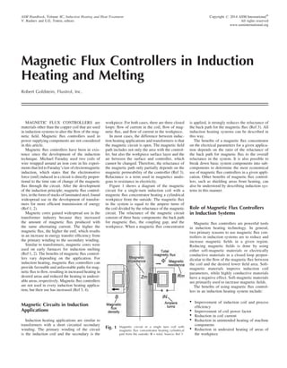
  • 1. Magnetic Flux Controllers in Induction Heating and Melting Robert Goldstein, Fluxtrol, Inc. MAGNETIC FLUX CONTROLLERS are materials other than the copper coil that are used in induction systems to alter the flow of the mag- netic field. Magnetic flux controllers used in power supplying components are not considered in this article. Magnetic flux controllers have been in exis- tence since the development of the induction technique. Michael Faraday used two coils of wire wrapped around an iron core in his experi- mentsthat led toFaraday’s law of electromagnetic induction, which states that the electromotive force (emf) induced in a circuit is directly propor- tional to the time rate of change of the magnetic flux through the circuit. After the development of the induction principle, magnetic flux control- lers, in the form of stacks of laminated steel, found widespread use in the development of transfor- mers for more efficient transmission of energy (Ref 1, 2). Magnetic cores gained widespread use in the transformer industry because they increased the amount of magnetic flux produced with the same alternating current. The higher the magnetic flux, the higher the emf, which results in an increase in energy transfer efficiency from the primary winding to the secondary winding. Similar to transformers, magnetic cores were used on early furnaces for induction melting (Ref 1, 2). The benefits of magnetic flux control- lers vary depending on the application. For induction heating, magnetic flux controllers can provide favorable and unfavorable paths for mag- netic flux to flow, resulting in increased heating in desired areas and reduced the heating in undesir- able areas, respectively. Magnetic flux controllers are not used in every induction heating applica- tion, but their use has increased (Ref 3, 4). Magnetic Circuits in Induction Applications Induction heating applications are similar to transformers with a short circuited secondary winding. The primary winding of the circuit is the induction coil and the secondary is the workpiece. For both cases, there are three closed loops: flow of current in the coil, flow of mag- netic flux, and flow of current in the workpiece. In most cases, the difference between induc- tion heating applications and transformers is that the magnetic circuit is open. The magnetic field path includes not only the area with the control- ler, but also the workpiece surface layer and the air between the surface and controller, which cannot be changed. Therefore, the reluctance of the magnetic path only partially depends on the magnetic permeability of the controller (Ref 3). Reluctance is a term used in magnetics analo- gous to resistance in electricity. Figure 1 shows a diagram of the magnetic circuit for a single-turn induction coil with a magnetic flux concentrator heating a cylindrical workpiece from the outside. The magnetic flux in the system is equal to the ampere turns of the coil divided by the reluctance of the magnetic circuit. The reluctance of the magnetic circuit consists of three basic components: the back path for magnetic flux, the coupling gap, and the workpiece. When a magnetic flux concentrator is applied, it strongly reduces the reluctance of the back path for the magnetic flux (Ref 3). All induction heating systems can be described in this way. The benefits of a magnetic flux concentrator on the electrical parameters for a given applica- tion depends on the ratio of the reluctance of the back path for magnetic flux to the overall reluctance in the system. It is also possible to break down basic system components into sub- components to determine the most economical use of magnetic flux controllers in a given appli- cation. Other benefits of magnetic flux control- lers, such as shielding areas from heating, can also be understood by describing induction sys- tems in this manner. Role of Magnetic Flux Controllers in Induction Systems Magnetic flux controllers are powerful tools in induction heating technology. In general, two primary reasons to use magnetic flux con- trollers in induction systems are to reduce and increase magnetic fields in a given region. Reducing magnetic fields is done by using either soft-magnetic materials or electrically conductive materials in a closed loop perpen- dicular to the flow of the magnetic flux between the coil and the desired lower field area. Soft- magnetic materials improve induction coil parameters, while highly conductive materials have a negative effect. Soft-magnetic materials are primarily used to increase magnetic fields. The benefits of using magnetic flux control- lers in an induction heating system include: Improvement of induction coil and process efficiency Improvement of coil power factor Reduction in coil current Reduction in unintended heating of machine components Reduction in undesired heating of areas of the workpiece ASM Handbook, Volume 4C, Induction Heating and Heat Treatment V. Rudnev and G.E. Totten, editors Copyright # 2014 ASM InternationalW All rights reserved www.asminternational.org Fig. 1 Magnetic circuit in a single turn coil with magnetic flux concentrator heating cylindrical part from the outside: F = total. Source: Ref 3
  • 2. Precise control of the magnetic field and resulting heat pattern Improvement in efficiency of high-frequency power supplying circuitry Reduction of external magnetic fields in close proximity to the coil In most applications, more than one of these benefits usually occurs (Ref 3–7). Recently, better understanding of the role magnetic flux controllers in induction heating systems has been obtained through comprehensive studies using computer simulation and experiments, such as those conducted at Fluxtrol, Inc. Results show that a magnetic flux controller properly used is typically beneficial in an induction heating system (Ref 3). Magnetic flux controllers play different roles in induction heating installations. Depending on the application, they are referred to as concentrators, controllers, diverters, cores, impeders, yokes, shunts, and screens. The effects of controllers in different types of induction heat- ing applications are described here. Materials for Magnetic Flux Control Two main categories of materials for mag- netic flux control are electrically conductive materials and magnetic materials. Electrically conductive materials typically are used in the form of shunts and screens to reduce external magnetic fields. Two main forms of magnetic materials are hard and soft. The difference is the amount of flux den- sity that remains after they are no longer exposed to a magnetic field. Hard magnetic materials retain a significant amount of the magnetic field, while soft materials retain almost no magnetic field when the source is turned off. Soft magnetic materials are used almost exclusively as con- centrators, controllers, diverters, cores, impeders, yokes, shunts, and screens for magnetic flux con- trol in induction systems. Highly Conductive Materials for Field Reduction Highly conductive materials in the form of closed loops are commonly used in induction systems to reduce the level of magnetic fields in certain areas. The effect on the distribution of the magnetic field is described by Lenz’s Law, which states an induced electromotive force always produces a current whose mag- netic field opposes the original change in magnetic flux. This current creates a field of reaction that influences the distribution of the magnetic field, and increases both the reluc- tance of the magnetic circuit and the current in the coil to produce the same amount of heat in the workpiece. These closed loops, com- monly referred to as Faraday, or “robber” rings carry high frequency currents, which result in heating by Joule losses. The losses reduce the efficiency of the system, and are not desirable. Therefore, nonmagnetic materials with high electrical conductivity are preferred for use as Faraday rings. Copper is the most common material used, but other materials, such as alu- minum, are used due to cost and/or weight considerations. Soft Magnetic Materials for Magnetic Flux Control Soft magnetic materials most commonly used in induction systems are laminations and soft magnetic composites. Soft magnetic ferrites are used occasionally in some high-frequency appli- cations. The main requirements are that it should have a relative magnetic permeability 1 and should not have a good electrically conductive path for strong eddy current generation. Placing the material in the path of magnetic flux lowers the reluctance of that part of the magnetic circuit. Therefore, it requires less cur- rent to drive the magnetic flux through that part of the circuit, and a higher percentage of flux flows in the magnetic material than would flow in the same space containing only air. However, this positive effect has some limita- tions because the magnetic circuit is almost always open. For the same coil current, workpiece power increases with increasing concentrator per- meability very fast initially, then approaches the threshold value asymptotically. At the same time, losses in the induction coil often increase slowly with increasing concentrator permeability. Computer simulation was used to demon- strate the diminishing positive effect of very high permeabilities in induction applications. In a real induction heating application, the mag- netic permeability of a magnetic flux controller depends on magnetic flux density, frequency, and temperature of the controller itself (not the part it is heating). In the study, permeability in the magnetic flux controller is considered to be constant in the cross-section and at a fixed value for each calculation. The study was not conducted for a particular material, but is used only to show the effect of conductor permeabil- ity on induction coil parameters. Figure 2 shows the effects of magnetic per- meability on coil current and efficiency for heating a flat plate using a single leg of an inductor at frequencies of 3 and 10 kHz. Simi- lar studies show that in most induction heating applications, the threshold value for workpiece power occurs when concentrator permeability is 100. In high-frequency induction heating applications, the threshold value occurs at lower levels of permeability. Therefore, incre- asing permeability to higher values will not improve coil parameters significantly (Ref 3). In some cases, use of materials with higher than optimal magnetic permeability reduces induction coil lifetimes without any benefits (Ref 3, 8, 9). Other important properties of soft magnetic materials, such as good saturation flux density, stable mechanical properties, low magnetic losses, chemical resistance, and resistance to elevated temperature depend on the application. Laminations are commonly made of coated thin sheets of silicon electrical steel with 3 or 4% silicon. The laminates are cut (by water jet, laser, CNC, and electrical discharge machin- ing) or stamped to the required shape for use in induction coils. For induction coils, multiple laminations are stacked between mechanical supports called keepers (Fig. 3). The large lamination cross section is oriented so it is in the plane of the flow of the magnetic field; intense eddy current heating occurs if it is not in the plane. Lamination thickness varies based on fre- quency used to limit eddy-current losses from the in-plane magnetic field. The lamination coat- ing prevents an electrical connection between individual laminations. In line-frequency appli- cations, individual laminations are typically between 0.020 to 0.040 in. (0.5 to 1 mm) thick. Laminations can be as thin as 0.002 in. in appli- cations using higher frequencies. Laminations have very high magnetic perme- ability and saturation flux density. They also have high temperature resistance limited pri- marily by the coating. The primary drawbacks of laminations are intense heating in 3-D mag- netic fields and limited frequency range (up to about 30 kHz). Soft Magnetic Composites consist of a soft-magnetic component (typically iron and iron-base alloy powder metal) and a dielectric component (usually an organic polymer binder). The soft-magnetic component provides a favor- able path in which the magnetic field can flow. The dielectric component electrically insulates magnetic particles from each other to limit eddy current losses. Two main forms of soft-magnetic composites are machinable and formable. Machinable materials are commonly produced via powder metallurgy compaction techniques and heat treated to improve magnetic and mechanical properties. Machining soft-magnetic compo- sites is easier than machining laminations. The composites are applied on induction coils using an adhesive and mechanical supports (Fig. 4). Machinable-soft magnetic composites have good magnetic permeability and saturation flux density, as well as good temperature resistance, which is limited primarily by the polymer binder. Unlike laminations, soft-magnetic com- posites can be tailored to work in the entire range of frequencies for induction heating and melting, and perform well in 3-D magnetic fields (Ref 3–7). Formable soft-magnetic composites are shaped around the induction-coil surfaces, held in place mechanically, and cured in an oven, which fixes their shape. Magnetic properties of formable soft magnetic composites are not as favorable as those of machinable composites, and are used in 634 / Equipment
  • 3. instances of irregular geometries and use of a machined material is difficult. Figure 5 shows relative magnetic permeabil- ity versus magnetic field strength of some com- mon soft-magnetic composites (Ref 4). Their diverse properties offer the opportunity for fine control using different materials on the same induction coil. Design Guidelines for Using Magnetic Flux Controllers on Induction Coils The decision of where to use a magnetic flux controller depends strongly on the shape of the induction heating coil. Many induction coils are hybrids and have components made of more than one of the basic coil types. Therefore, it is important to understand how magnetic flux flows and how it is affected by a magnetic flux controller to properly apply it on more complex induction coils. Effects of Magnetic Flux Controllers on Common Coil Styles Outer Diameter (OD) Coils. The basic magnetic circuit for an OD coil (Fig. 1) was described previously. Computer simulation is used to visualize and quantify the effects of a magnetic flux controller on an induction heat- ing system (Ref 3–7). Figure 6 shows magnetic field lines and current density in a single-turn OD coil for heating a cylindrical copper work- piece with and without the use of a magnetic flux controller. The same voltage (similar value of magnetic flux) is applied to each coil. The process was simulated using Cedrat Technolo- gies Flux 2D software. A copper workpiece was used so current density values in the induc- tion coil and workpiece were similar to make visualization of the effects easier. The magnetic field is distributed in a smaller area for the coil with the magnetic flux control- ler, and the resulting current density in the part is concentrated under the coil heating face. Nearly all of the power induced into the part is useful, and leads to an increase in tempera- ture in the desired heating area. Nearly all of the current in the coil with the magnetic flux controller flows on the heating face. In the coil without a magnetic flux controller, a significant portion of the current flows in areas outside of the heating face, which does not help heating the part, but instead, draws additional power from the power supply. A significant por- tion of current in the coil flows up the sides of the turn and around the back; this current is not use- ful and only leads to additional losses in the coil, busswork, and matching components. The reduction in current in the coil and con- centration of power under the heating face is called the concentrator effect (Ref 3, 10, 11), and can be explained by considering the system from a magnetic circuit point of view (see Fig. 1). The concentrator effect is a result of the magnetic flux controller lowering the Fig. 2 Effect of magnetic permeability on coil current (a) and efficiency (b); curves generated from computer simulation of heating a flat plate using a single leg of an inductor; 50 kW in the part under the coil face. Source: Ref 3. Fig. 3 Induction coil with laminations stacked bet- ween mechanical supports. Courtesy of Tucker Induction. Fig. 4 Induction coil with soft magnetic composites. Source: Ref 3 Magnetic Flux Controllers in Induction Heating and Melting / 635
  • 4. reluctance of this portion of the magnetic cir- cuit and reducing the need for current in this area of the induction coil to drive the magnetic flux around the back path. The primary benefits of magnetic flux con- trollers on OD induction coils are: Higher efficiency Improved heat pattern control (ability to heat fillets, not overheat shoulders, obtain sharper transition zones, etc.) Better use of power in the workpiece (energy savings) Reduction in the induction coil current (reduced losses in power supplying circuitry) Reduction in heating of unintended areas of the part Reduction in heating of machine/structural components Reduction in external magnetic fields The aspect ratio of the induction coil must be considered to determine the impact of a mag- netic flux controller on an OD coil. Two key variables are the ratio of coil length to diameter, and the ratio of the coupling gap to the length of the coil. Magnetic flux controllers are most benefitial when the length-to-diameter ratio and coupling gap-to-length ratio are small. The effects of the magnetic flux controller are reduced as these ratios increase. For very large coupling gaps relative to coil length, a magnetic flux controller can result in lower electrical efficiency. Inner Diameter (ID) Coils. The basic mag- netic circuit for an ID coil is shown in Fig. 7. The return path for magnetic flux is on the inside of the coil. Power density in the workpiece is proportional to the magnetic flux density squared, and flux density is magnetic flux divided by the cross-sectional area through which it is flowing. The magnetic impedance of an area is directly proportional to the length of the region and inversely proportional to the cross-sectional area. Therefore, the magnetic resistance (Rm) component is a higher percentage of the total reluctance on an ID coil than it is on an OD coil. Due to the larger influence of Rm, the effect of a magnetic flux controller on ID coils is much larger than on OD coils (Ref 3, 12). Benefits of magnetic flux controllers on ID induction coils include: Improved coil efficiency (energy savings) Better use of power in the workpiece (energy savings) Reduction in induction-coil current (reduced losses in power supplying circuitry, coil leads) Reduction in heating of unintended areas of the part Improved heat pattern control Magnetic flux controllers significantly improve nearly all ID coils. To determine the impact Fig. 5 Magnetic permeability of some Fluxtrol soft-magnetic composite materials as a function of magnetic field strength. Color Shade Results Quantity : |Current density| A/(square mm) Phase (Deg): 0 Scale / Color 0 / 14.8125 14.8125 / 29.625 29.625 / 44.4375 44.4375 / 59.25 59.25 / 74.0625 74.0625 / 88.875 88.875 / 103.6875 103.6875 / 118.5 118.5 / 133.3125 133.3125 / 148.125 148.125 / 162.9375 162.9375 / 177.75 177.75 / 192.5625 192.5625 / 207.375 207.375 / 222.1875 222.1875 / 237 Color Shade Results Quantity : |Current density| A/(square mm) Phase (Deg): 0 Scale / Color 0 / 14.8125 14.8125 / 29.625 29.625 / 44.4375 44.4375 / 59.25 59.25 / 74.0625 74.0625 / 88.875 88.875 / 103.6875 103.6875 / 118.5 118.5 / 133.3125 133.3125 / 148.125 148.125 / 162.9375 162.9375 / 177.75 177.75 / 192.5625 192.5625 / 207.375 207.375 / 222.1875 222.1875 / 237 Fig. 6 Magnetic field lines and current density for a single-turn OD coil with (left) and without (right) a magnetic flux controller. Courtesy of Fluxtrol, Inc. Fig. 7 Magnetic circuit for ID coil. Source: Ref 3 636 / Equipment
  • 5. on the coil, it is necessary to consider the coil aspect ratio. Similar to OD coils, two key vari- ables are the coil length-to-diameter ratio and the coupling gap-coil length ratio. Unlike OD coils, aspect ratios that benefit most from a magnetic controller are inverted. Magnetic flux controllers provide the greatest benefit when the two ratios are larger. Linear Coils. Three basic classes of linear induction coils are: Coils with return current on the opposite side of the part (e.g., single-shot coils, oval coils, channel coils) Coils with one primary heating leg and distributed return on the same side of the part (vertical loop, split-n-return coils) Coils with two active heating directions and return on the same side of the part (hairpin) The difference between linear induction coils and cylindrical coils is there is no natural flux concentrating/de-concentrating effect from the change in radius in linear coils. Therefore, the only other electromagnetic effects present are the proximity effect between coil and work- piece and the proximity effect between the coil turns themselves in the case where the return is on the same side of the part. A hairpin inductor (magnetic circuit shown in Fig. 8) is used to illustrate the concept of a magnetic circuit for linear coils. If the coil legs are the same size and part properties under each leg are the same, each leg produces one half of the magnetic flux in the system. Magnetic flux flows around the legs of each turn. In the region between the two turns, magnetic flux from each turn are additive, and the all magnetic flux from the system flows through this area. At the same time, the cross-section through which the mag- netic flux must flow is smaller than the areas of the back path for magnetic flux. Thus, the Rm value is high on hairpin coils, and the bulk of Rm resides in the region between the two turns (Ref 3). This phenomenon also occurs in other types of linear inductors (e.g., vertical loop, split-n- return) where the return is on the same side of the inductor; the bulk of Rm resides in the area between the turns that are in the opposite direction. Use of a magnetic flux controller in this area is very beneficial. The benefit is greatest for aspect ratios where the distance between turns relative to the coupling gap is small. The benefit is less when the heat face is long and the return is on the opposite side of the part. Cooling of Magnetic Flux Controllers The service life of induction heating coils with magnetic flux controllers varies from days to years. Cooling the magnetic flux controller minimizes mechanical damage and increases service life. Heat Sources in Magnetic Flux Control- lers. All magnetic flux controllers generate and absorb heat when exposed to an alternating magnetic field. The amount of heat depends on induction system parameters, induction coil and part geometry, magnetic flux controller material, part temperature, and the atmosphere surrounding the coil. Highly conductive nonmagnetic materials are heated by eddy currents, radiation and conduc- tion from the hot part, and convection from the hot environment. The main heat source is from eddy currents. Because Faraday rings use the eddy-current reaction field, the primary ways to reduce losses is to use low-resistivity materials and increase the length of the shield- ing face. Soft-magnetic materials are heated by eddy currents, heat from thermal sources, hysteresis losses, and sometimes by conductive heat trans- fer from the copper coil. Unlike highly conduc- tive nonmagnetic materials, shielding in soft- magnetic materials is by concentration of fields of reaction rather than by reduction of the fields. Therefore, soft-magnetic materials are segmented perpendicular to the plane of the magnetic field at a small fraction of reference depth to minimize eddy currents. The electrical resistivities of laminations are similar to those of steels, so individual lam- ination thickness should be between 0.002 to 0.040 in. depending on frequency. With proper lamination thickness, eddy current losses in 2-D magnetic fields make up a small portion of the heat that needs to be removed. In 3-D magnetic fields, eddy current losses grow rapidly in laminations and are larger than the other heat sources (Ref 3). Soft-magnetic composites typically have electrical resistivities several orders of mag- nitude higher than those for laminations. In general, composites that will be used in higher frequency applications should have higher electrical resistivities. Therefore, the allowable thickness of soft-magnetic composites is much larger, enabling fabrication of the concentrator from one or only a few components. Global eddy current losses in soft-magnetic composites generally make up a small fraction of the total heat (Ref 3). For soft-magnetic composites, besides global eddy current losses, there are also eddy currents in the individual magnetic particles. Similar to eddy currents in larger bodies, losses in individ- ual particles are controlled by particle size and composition. Smaller particles are typically used for higher frequencies. In most induction applications, eddy current losses in individual particles make up only a small portion of the total heat (Ref 3). When the correct magnetic flux controller is used, hysteresis losses make up the largest com- ponent of heat that must be removed. Hysteresis losses are due to internal friction of magnetic domains as they reorient in the presence of an alternating magnetic field. A hysteresis loop is used to characterize mag- netic hysteresis for a given magnetic material (Fig. 9). Key points on the curve are saturation flux density, remanence, and coercive force. Sat- uration flux density is the threshold value for the magnetization of the material. Remanence is the magnetism that remains after removingFig. 8 Magnetic circuit for a hairpin inductor coil. Source: Ref 3. Magnetic Flux Controllers in Induction Heating and Melting / 637
  • 6. the source of the magnetic field. Coercive force is a measure of how much magnetic field must be applied in the opposite direction to remove the remanence. Losses in a magnetic material due to hystere- sis are proportional to the product of the area of the hysteresis loop and the frequency. For good soft-magnetic materials, the hysteresis loop should be as narrow as possible. Minimizing hysteresis losses is accomplished through alloy- ing elements and by stress relieving the mate- rial (Ref 3). Heat Removal in Magnetic Flux Control- lers. The cooling method depends on the type of magnetic flux controller used and the process environment. Power density losses in Faraday rings are higher than in soft-magnetic materials. However, removing this heat is eas- ier due to the nature of the materials. Depend- ing on the magnitude of eddy current losses, Faraday rings can be cooled using internal water cooling, free convection, and conduction to a large structure. Losses in soft-magnetic materials (approxi- mately directly proportional to frequency) are small compared with those in the copper coil, which are usually proportional to the square root of frequency. For low frequencies, the ratio between copper losses and soft magnetic losses is large. It is smaller at higher frequencies, but copper losses are still the dominant factor in total coil losses below several MHz. For soft-magnetic materials operating at low frequencies or low power densities, cooling by free convection is sufficient to maintain a satis- factory temperature provided the atmosphere is at a temperature low enough to remove heat and the magnetic core is not continuously exposed to direct radiation from a hot part. For medium frequencies and power densities, the most common method to remove heat is con- duction to the water-cooled copper (Fig. 10). A thermally conductive adhesive is placed between the soft-magnetic material and copper tubing to facilitate heat removal. Desirable thermal conductivities of laminations and soft- magnetic composites are 15 to 100 times lower than that for copper, and the thermal con- ductivity of adhesives is even lower. Adhesive layer thickness, consistency of gap filling, and adhesive thermal conductivity each play a critical role in heat removal from the magnetic flux controller. The use of a 0.010-in. (0.25-mm) layer of an epoxy adhesive (1 W/mK thermal conductivity) with Fluxtrol materials is suffi- cient for heat removal in most cases (Ref 4). In instances of heavy loading, a supplemental water-cooling plate applied to the backside of the magnetic flux controller increases heat extraction. Direct water cooling could be required in appli- cations involving very heavy loading. Cooling methods include water channels in the concentra- tor (for soft-magnetic composite only, Fig. 11), supplemental water drizzle and quench head for quench-in-place applications. A coating on water cooling channels is recommended when using direct water cooling of magnetic flux controllers to prevent water cooling-system contamination. Computer simulation shows that Fluxtrol 100 material can withstand continuous operation at a magnetic flux density of 1 T, a frequency of 1 kHz, and direct exposure to radiation from a 1200 C (2190 F) part using direct water cooling (Fig. 12). Fig. 11 Soft magnetic composite material with channels for direct water cooling. Source: Ref 4 Fig. 10 The most common method to remove heat from a magnetic flux controller is by conduction to the water- cooled copper coil. Source: Ref 3 Fig. 9 Hysteresis loop for magnetic materials. Source: Ref 3 638 / Equipment
  • 7. Determining the Thickness of Soft Magnetic Material The amount of soft-magnetic material required is determined by considering magnetic flux density, mechanical strength, and physical space available for the application. Magnetic flux density is important because both magnetic permeability and magnetic losses are dependent on it. Magnetic flux density should not exceed the saturation flux density of the magnetic con- troller unless there is limited available space and only partial shielding is required. To determine magnetic loading, it is neces- sary to determine the magnetic flux density B in the magnetic material. For a long solenoid, it can be determined from Eq 1 if the magnitude of voltage on the coil head is known, or from Eq 2 if the magnitude of the coil current is known. In an electrical circuit, the magnetic permeability of the material is a function of magnetic flux density: B ¼ U oSN (Eq 1) B ¼ IN l (Eq 2) where B is magnetic flux density, U is coil volt- age, o is angular frequency, S is cross-sectional area, N is number of turns, m is magnetic per- meability, and l is length. For most other coil styles, Eq 1 and 2 can provide a rough estimate of flux density. Eq 1 is better for ID coils. Computer simulation pro- vides the best information. Magnetic Flux Control in Induction Melting Systems Three types of induction melting systems are channel-type, crucible-type, and cold crucible. Only the role of magnetic flux controllers in an induction melting system is discussed here. Details of each type of induction melting sys- tem are discussed elsewhere in this Volume. Channel Type Furnaces Channel melting furnaces are similar to either a transformer or an ID coil (Fig. 13). They should always have a magnetic flux controller or better system efficiency. Channel furnaces operate at low frequencies and are used primarily to pro- duce large volumes of metal. For this reason, laminations are the material of choice due to lower cost and availability in large sizes. Crucible Type Furnaces Crucible type furnaces consist of a solenoid induction coil and a ceramic refractory or con- ductive (graphite or metal) crucible. Magnetic flux controllers are used on these furnaces pri- marily to reduce external magnetic fields, which can cause heating of the equipment structure, or can necessitate a very large footprint due to occu- pational safety limits for human exposure to electromagnetic fields. Large Low-Frequency Melting Furnaces. Faraday rings and shunts are used in many large furnaces; shunts are used on the OD of the induction coil and a combination of Faraday rings and counterwound turns are used on the top and bottom of the coil. A crucible melting furnace is shown in Fig. 14. The design is typical of low-frequency (tens to hundreds of Hertz) fur- naces used to melt large volumes of metal. Shunts used in these furnaces generally are silicon steel laminations contained in a metal support structure. Silicon-steel shunts work well on the back of the induction coil because the field is regular, in one direction, and of a simple geometry. Shunt assemblies with lami- nation shunts are less expensive than alternative materials such as soft-magnetic composites for large low-frequency furnaces. Incorporating laminations on the top and bot- tom of the induction coil is more difficult, which is why a combination of counterwound turns and/or Faraday rings is used to reduce the level of magnetic fields in this area. These methods effectively control external fields, but reduce coil efficiency. Fig. 12 Computer simulation of heat removal from soft-magnetic material exposed to a magnetic flux density of 1 T, a frequency of 1 kHz, and a 1200 C part by direct water cooling. Source: Ref 4 Fig. 13 Schematic of channel-type induction melting furnace. Source: Ref 13 Fig. 14 Sketch of induction crucible-type (coreless) melting furnace. Source: Ref 2 Magnetic Flux Controllers in Induction Heating and Melting / 639
  • 8. An alternative method is to use a soft-magnetic composite ring on the top of the induction coil backed by a Faraday ring. The composite strongly reduces the level of magnetic field to which the Faraday ring is exposed with lower losses than using counterwound turns. Losses of this type of assembly are much lower while providing the same level of shielding. A drawback of this approach is higher initial cost. Capital versus operating costs should be considered when choos- ing between top and bottom shielding. Medium-Size Medium-Frequency Melting Furnaces. Magnetic flux controllers are used for the same purposes on 1 to 10-kHz frequency medium-size furnaces as for larger ones, but different materials are used. Many of these fur- naces operate in a controlled atmosphere, where magnetic flux controllers are more important than in open air furnaces. The controllers could be used to shield the chamber from heating. Furnace size must be larger without the use of magnetic flux controllers, increasing the capital cost of the installation. Lamination thickness decreases with increas- ing frequency making them more difficult to work with. Also, shount pack structural materials heat up more at higher frequencies, resulting is an increased cost of using laminate shunt packs. Due to these factors, the use of soft-magnetic composites is becoming more popular for medium-size melting furnaces. Figure 15 shows a medium-size melting coil with a Fluxtrol 100 soft-magnetic composite. This makes it possible to incorporate magnetic poles on the top and bottom of the induction coil, so it is not neces- sary to counterwind the upper and lower turns or use a Faraday ring. Therefore, the entire length of the induction coil works together to create the internal magnetic field. Another benefit of magnetic flux controllers in these furnaces is when multiple melting pots are placed in close proximity to each other. The furnaces can be controlled using either one power supply or multiple power supplies. How- ever, the magnetic fields of different pots inter- act if they are placed too close to one another. This phenomenon is called cross-talking, and it can cause nonuniform melting pot performance. Magnetic flux controllers greatly reduces the amount of cross-talking. Cold-Crucible Melting Furnaces In cold-crucible furnaces, a water-cooled seg- mented copper ring is placed between the induction coil and the melt. Magnetic flux flows through the slots of the cold crucible and heats the melt. Water-cooled Faraday rings are often used on the bottom of the furnace. A metal skull typically forms between the melt and the copper components, which creates a barrier that prevents contamination of the melt by impurities. These furnaces are less efficient than coreless melting furnaces due to electrical losses in the segmented copper ring, the lower Faraday Fig. 15 Medium-sized melting coil with soft- magnetic shunts. Courtesy of Fluxtrol, Inc Traditional design PDmax = 216 MW/m3 Color Shade Results Quantity : Power density W/(cubic m) Phase (Deg): 0 Scale / Color 0 / 13.50879E6 3.50879E6 / 27.01758E6 27.01758E6 / 40.52636E6 40.52636E6 / 54.03515E6 54.03515E6 / 67.54394E6 67.54394E6 / 81.05274E6 81.05274E6 / 94.56152E6 94.56152E6 / 108.0703E6 108.0703E6 / 121.57909E6 121.57909E6 / 135.08789E6 135.08789E6 / 148.59667E6 148.59667E6 / 162.10546E6 162.10546E6 / 175.61426E6 175.61426E6 / 189.12304E6 189.12304E6 / 202.63182E6 202.63182E6 / 216.14061E6 Modified design PDmax = 279 MW/m3 Color Shade Results Quantity : Power density W/(cubic m) Phase (Deg): 0 Scale / Color 0 / 17.47247E6 17.47247E6 / 34.94494E6 34.94494E6 / 52.41741E6 52.41741E6 / 69.88988E6 69.88988E6 / 87.36234E6 87.36234E6 / 104.83482E6 104.83482E6 / 122.30729E6 122.30729E6 / 139.77976E6 139.77976E6 / 157.25224E6 157.25224E6 / 174.7247E6 174.7247E6 / 192.19717E6 192.19717E6 / 209.66965E6 209.66965E6 / 227.14211E6 227.14211E6 / 244.61459E6 244.61459E6 / 262.08706E6 262.08706E6 / 279.55952E6 Fig. 16 Comparison of power density in the melt charge derived from a 2-D simulation using Flux 2D software: (a) traditional induction coil design with laminate shunts, and (b) modified design with a soft-magnetic composite controller with top and bottom shunts. Source: Ref 14 640 / Equipment
  • 9. ring, and thermal losses of the melt to the water- cooled copper components. Therefore, cold- crucible melting furnaces are typically used only in the production of metals that are highly reactive when molten or that require very low impurities. Cold-crucible processes almost always are carried out in a controlled atmosphere. Magnetic flux controllers improve the effi- ciency of cold-crucible furnaces. Similar to other controlled-atmospheremelting applications,mag- netic flux controllers are used on the OD of the induction coil to shield the chamber from heating. Additional improvements are achieved by using magnetic poles on the top and bottom of the induction coil to reduce the losses associated with the Faraday rings on the top and bottom of the cold crucible. Studies show up to 50% improvement in induction coil efficiency using an induction coil with soft-magnetic composite top and bottom poles compared with a standard coil design (Fig. 16, 17) (Ref 14). Magnetic Flux Control in Mass-Heating Applications The role of magnetic flux controllers in an induction mass-heating system depends on the application. Of the many types of induction mass-heating installations, the largest applica- tion is heating component part prior to a shap- ing operation, such as forging, forming, and rolling. The role of magnetic flux controllers whole-body and local area mass-heating appli- cations is discussed here. Detailed discussion of these types of installations are presented elsewhere in this Handbook. Whole-Body Mass Heating Workpieces are large in most whole-body mass-heating applications, and the part passes through the induction coil. Part shape and induc- tion coil length are the primary determinants of the type of magnetic flux controller used in these systems. Long solenoids are used for long cylindrical or tubular body workpieces. Soft-magnetic con- trollers do not provide significant benefits for long solenoids (length = several times the diam- eter). Therefore, several induction coils are used to bring the billet up to the desired temper- ature distribution. In these installations, Fara- day rings at the end of the coils are the only magnetic flux controllers used (Fig. 18). They perform two functions: shielding mechanical handling rolls from heating and preventing cross-talking among multiple coils used in the billet-heating line. For rectangular workpieces, the benefits of a magnetic flux controller depend upon the aspect ratio of the cross-section to be heated. For square and nearly square parts, guidelines for magnetic flux controller and coil selection are similar to those for cylindrical and tubular parts. Magnetic flux controllers play a greater role for rectangular parts with one dimension significantly larger than the other (e.g., slabs, sheet, strip). In this case, both longitudinal and transverse flux heating methods are used. Longitudinal coils generate a uniform tem- perature in the cross-section. Soft-magnetic materials are beneficial when the length of the induction coil is small relative to the perimeter of the coil inside cross-section. Soft-magnetic materials should be used on transverse flux heating coils (Ref 3, 10, 15). Material selection depends on the frequency. Silicon steel laminations are used for low fre- quencies, and soft magnetic composites are used for middle and higher frequencies. Soft- magnetic composites are also used near the ends of low frequency transverse flux coils where 3-D magnetic fields are present. Local Area Mass Heating In many cases, it is desirable to heat only a portion of the component for forming. Local area mass heating can be achieved using both static and continuous heating arrangements. For static heating, both single-turn and multi- turn induction coils are used, where the coil l is comparable to the coil diameter. Soft-magnetic controllers applied to the induction coil improves temperature distribution and coil efficiency due to better use of power in the workpiece together with reduced coil current demand. Continuous heating applications use a chan- nel coil, which can be one turn to heat fasten- ers, for example (Fig. 19) or several turns as in a bar end heater (Fig. 20). Soft-magnetic controllers help significantly in both cases. For single-turn channel coils, use of soft- magnetic material reduces the power required to heat the desired area of the part by 20 to 50% (Ref 3, 4). Soft-magnetic composites are the material of choice because these applica- tions usually operate at 10 kHz or higher. Fluxtrol Design Ptotal (kW) Ptotal (kW) Pleads Pmelt Pcoil Pcrucible I(A) 122.5 6% 47% 15.5% 31% 1600 Traditional Coil Design Pleads Pmelt Pcoil Pcrucible I(A) 135 6.5% 31% 21% 41.5% 1900 Fig. 17 Comparison of integral power values for traditional induction coil design with laminate shunts and a Fluxtrol-designed coil with soft-magnetic composite controller with top and bottom shunts. Source: Ref 14 Fig. 18 Billet-heating coil with Faraday rings on both ends. Courtesy of Pillar Induction, Inc. Magnetic Flux Controllers in Induction Heating and Melting / 641
  • 10. The effect of soft-magnetic materials on channel coils with multiple turns for heating longer sections is not as strong as for shorter single-turn coils; energy savings is typically between 5 and 20% (Ref 3, 4). Magnetic Flux Control in Induction Tube-Welding Applications Induction tube welding is a major application of induction heating, used in high volume pro- duction of carbon-steel tubes. It is also used to produce stainless steel, copper, and aluminum tubing. Magnetic flux controllers play a crucial role in tube-welding lines, both in the welding process and post weld heat treatment. Magnetic Flux Controllers for Continuous Induction Tube Welding In an induction tube welding process, steel strip is rolled into the form of a tube and passed through a cylindrical induction coil where the strip edges are heated. The strip passes through a final set of rollers that close the profile of the tube and welding occurs. Induction welding systems for steel tubing operate at high fre- quencies (100À500 kHz) and high power (in the range of 100 kW to a few MWs). Figure 21 shows a schematic of current flow in the tube in a typical induction welding appli- cation. The induction coil induces a current that flows around the tube OD under the face of the induction coil. When the current reaches the open edge of the tube, it turns to close the current loop. Three options for the current to flow are: 1. Along the edges of the steel strip toward the rolls, connecting at the weld apex and return- ing back on the opposite edge of the tube 2. Along the edges away from the V-shape groove, returning on the tube OD of the tube farther up the line 3. Along the tube ID The first current path is the most desirable one, the second path is somewhat useful, and the third path is undesirable. In induction welding applications, a soft-magnetic material is placed inside the tube to reduce heating along the ID of the tube and to enhance current flow along the tube edges toward the V groove. The soft-magnetic material on the tube ID of the tube is referred to as an impeder, because it impedes current flow along the tube ID. Impeders are made of soft magnetic ferrites encased in a fiberglass tube with water cooling. The tube protects the ferrite from metal spume and provides mechanical support for the brittle ferrites. The tube also keeps the ferrites in place as they often fracture in production due to ther- mal shock. Figure 22 shows some typical impe- ders used in the welding industry. For large pipe Fig. 20 Continuous bar-end heater with magnetic flux concentrator. Courtesy of Fluxtrol, Inc. Fig. 19 Channel coil for fastener heating. Courtesy of Fluxtrol, Inc. Fig. 21 Schematic of a continuous high-frequency induction longitudinal seam tube-welding system. Source: Ref 13 Fig. 22 Impeders for small-tube welding; used for current flow along the tube ID. Source: Ref 16 642 / Equipment
  • 11. welding systems, the impeder consists of multi- ple impeders assembled together, referred to as a cluster impeder (Fig. 23). Ferrites are the material of choice in most tube-welding applications due to their low cost, high magnetic permeability at lower flux densi- ties, and low losses at high frequencies. The drawbacks of ferrites are low-saturation mag- netic flux density, sensitivity to thermal shock, and sensitivity of magnetic properties to tem- perature change. The life of ferrites in the case of small tubes ranges from several hours to a week. The mag- netic flux density in the impeder core is higher due to the smaller cross-section inside the tube, and ferrites become saturated. In some instances of short impeder life, ferrites have been replaced with Fluxtrol 75 soft-magnetic composite, result- ing in 10 to 30% energy savings and increased life (Ref 17). The efficiency of tube welding systems is improved using an external magnetic bridge (Ref 18). A soft-magnetic composite material placed above the tube opening helps increase current flow along the weld “V” and helps balance heating of the top and bottom edges of the tube wall (Fig. 24). In some applications, the benefits of using an external magnetic bridge are 20 to 30% energy savings and improved weld quality. System improvements from using a magnetic bridge depend on the configuration of the weld rolls. To achieve sig- nificant benefits, the magnetic bridge must be close to the weld apex without moving the coil farther away from it. Magnetic Flux Controllers for Seam-Annealing Inductors In some cases, the weld seam requires anneal- ing to relieve stresses from the welding process or to improve the microstructure. To accomplish this, induction heating is commonly used, referred to as seam annealing. In instances of high production rates and for heavy-walled pipe, several seam annealers are placed in series. Seam-annealing inductors are linear induc- tors, either vertical loop or split-n-return, operating at 1 or 3 kHz frequency and power levels of hundreds of kWs. Figure 25 shows a typical seam-annealing induction coil in the field. C-shaped soft-magnetic materials (lamina- tions or soft-magnetic composites) are placed over the central turn to concentrate heat on the weld seam. Magnetic flux controllers are not used on the return leg (vertical loop) or legs (split-n-return), because it is desirable to widely distribute the return current to minimize heat generated by those turns. Magnetic Flux Control in Local Heat Treating Applications Surface hardening of machinery components using induction is a common application. The main advantage of induction heat treating com- pared with other heat treatment methods is the ability to quickly and selectively heat only the areas of the workpiece where property modification is desired. This results in lower distortion, more favorable residual stress distri- bution, better microstructure, significant energy savings, and the ability to place the induct- ion system in-line with other manufacturing operations. Application of magnetic flux con- trollers, primarily in the form of soft-magnetic Fig. 23 Cluster impeder (multiple impeders assembled together) for large diameter pipe welding. Courtesy of Electronic Heating Equipment, Inc. Fig. 24 Influence of a magnetic bridge on weld temperature distribution for a 40 mm OD by 2.5 mm thick tube traveling at a line velocity of 75 m/min; the bridge helps balance heating of the top and bottom edges of the tube wall. Source: Ref 4 Fig. 25 Seam annealer for tube-welding line. Courtesy of EFD Induction Magnetic Flux Controllers in Induction Heating and Melting / 643
  • 12. materials, are particularly well suited for use in heat treating applications, because they strongly influence the power density value and its distri- bution along the surface of the workpiece, enabling faster heating and better heat pattern control (Ref 3–6). All induction heat treating processes can be classified in two categories: single shot and scanning, based on whether the induction coil is moving (excluding rotation) relative to the part during the heating process. A brief discus- sion of the benefits of magnetic flux controllers in these cases follows. Single-Shot Heat Treating In single-shot induction heat treating applica- tions, the position of the induction coil relative to the heated length of the part does not move. In many single-shot heating applications, the part rotates while heating and quenching occur to ensure uniformity of pattern. Within the fam- ily of single-shot heat treating applications, there are several varieties of induction coil configura- tions. Common induction coil styles used for heat treating include linear coils, ID coils, encir- cling coils, and encircling/non encircling coils. The most important role of soft-magnetic mate- rials in these applications is to control the distribu- tion of temperature and ensure good part quality. This is especially important near the ends of the induction coil to control run-out or in central areas where there are geometry changes. Secondary benefits of soft-magnetic materials in these applications are energy savings and lower coil currents. This is especially important in app- lications such as simultaneous dual-frequency hardening of gears, where power levels at high frequency tend to be large. Lower currents reduce the coil kVAs, and allow for smaller transformers and matching components, which reduce overall system cost. Soft-magnetic materials most commonly used for induction heat treating applications are lami- nations and soft-magnetic composites. In some applications, a combination of laminations and soft-magnetic composites are used on the same coil. Laminations are more common on longer linear coil sections at lower heat treating fre- quencies (1–10 kHz). Soft-magnetic composites are more common on medium to high frequency linear coils (10 kHz and up) and coils with short linear sections. For coils with circular sections, soft-magnetic composites are more popular in most cases due to ease of application. Induction Scan Heat Treatment In induction scan heat treatment applications, the position of the induction coil relative to the heated length of the part does move. In many scanning applications, the part rotates during heating and quenching to ensure uniformity of pattern. Within the family of scanning applica- tions, induction coil configurations are not as diverse as for single shot. Common induction coil styles used for scanning include encircling coils, short linear coils, and channel coils. Encircling coils likely are the most common for induction scanning (Fig. 26). In induction scanning applications with encircling coils, the main benefit of a magnetic flux controller is in heat pattern control at the beginning and end of the part. Energy savings from the application of magnetic flux controllers is less than in the case of single-shot coils, because much of the stray heating before and after the coil is still used in the scanning process to contribute to the case depth. In some instances, such as axle scan hardening, where the heat treatment in the fillet area drives the design, magnetic flux controllers improve the pattern and achieve energy savings between 15 and 50% (Ref 4, 17, 19). Figure 27 shows some induction scan hardening coils with magnetic flux controllers used for axle scan hardening. Linear coils commonly are used for scan- ning large components, such as hardening bearing races on slewing rings, and tooth-by- tooth hardening of large gears. Other applications are scan hardening of components where there is a large geometrical change. Nearly all short lin- ear scanning coils use soft magnetic materials, because they are necessary for heat pattern con- trol and provide large energy savings. Channel coils are commonly used for in-line heat treatment and brazing of smaller components, such as hardening or tempering of nuts and bolts, brazing of cutting bits, and hardening of saw blade teeth. Magnetic flux controllers are used for heat pattern control and efficiency improvement. Most of these installations oper- ate at higher frequencies, so soft-magnetic compo- sites are the material of choice when a magnetic flux controller is used. REFERENCES 1. A. Muhlbauer, History of Induction Heat- ing, Vulcan Verlag GmbH, Huyssenallee, Essen, Germany, 2008 2. V. Rudnev, et al., Handbook of Induction Heating, Marcel Dekker, New York, 2003 3. V.S. Nemkov, “Resource Guide for Induc- tion Heating, CD-R,” Fluxtrol Inc., 2006 4. www.fluxtrol.com 5. R.S. Ruffini, R.T. Ruffini, and V.S. Nemkov, Advanced Design of Induction Heat Treating Coils, Part I: Design Principles, Industrial Heating, June 1998. 6. R.S. Ruffini, R.T. Ruffini, and V.S. Nemkov, Advanced Design of Induction Heat Treating Coils, Part II: Magnetic Flux Concentration and Control, Industrial Heating, Nov 1998 7. R.T. Ruffini, V.S. Nemkov, and R.C. Goldstein, “Prospective for Improved Magnetic Flux Control in the Induction Heating Tech- nique,” presented at 20th Heat Treating Soci- ety Conference and Exposition, St. Louis, 2001 8. R.C. Goldstein, et al., “Virtual Prototyping of Induction Heat Treating,” 25th Heat Treating Society Conference and Exposi- tion, Indianapolis, Sept, 2009 Fig. 26 Induction scan-hardening coils made of formed tubing. Source: Ref 4 Fig. 27 Two-turn scan hardening coil with magnetic flux controllers used for axle scan hardening. Source: Ref 4 644 / Equipment
  • 13. 9. Myers, et al., Optimizing Performance of Crankshaft Hardening Inductors, Industrial Heating, Dec 2006 10. S. Lupi, et al., Induction Heating Industrial Applications, France 1992 11. V.S. Nemkov, and R.C. Goldstein, Design Principles for Induction Heating and Hard- ening, Handbook of Metallurgical Process Design, G. Totten, K. Funatani, and L. Xie, Eds., Marcel Dekker, New York 2004 12. V.S. Nemkov, et al., “Optimal Design of Internal Induction Coils,” Intl. Symposium on Heating by Electromagnetic Sources, Padua, Italy, June 2004 13. Bialod, et al., Induction Heating: Industrial Applications, UIE, 1991 14. Heidlhoff, et al., “Advancements in Ti Alloy Powder Production by Close- Coupled Gas Atomization,” Advances in Powder Metallurgy Particulate Materi- als, 2011 15. Spagnolo, et al., “Space Control Optimi- zation of Multi-Coil Transverse Flux Induction Heating of Metal Strips,” Intl. Symposium on Heating by Electromagnetic Sources, Padua, Italy, May 2010 16. www.startechnologica.com.br 17. Fluxtrol internal documents 18. V.S. Nemkov, Magnetic Flux Guide for Continuous High Frequency Welding of Closed Profiles, U.S. Patent Application 20080308550, Dec, 2008 19. R.C. Goldstein, et al., “Optimizing Axle Scan Hardening Inductors,” 24th Heat Treating Society Conference and Exposi- tion, Detroit, Sept 2007 Magnetic Flux Controllers in Induction Heating and Melting / 645