Downloaded 33 times
![Page
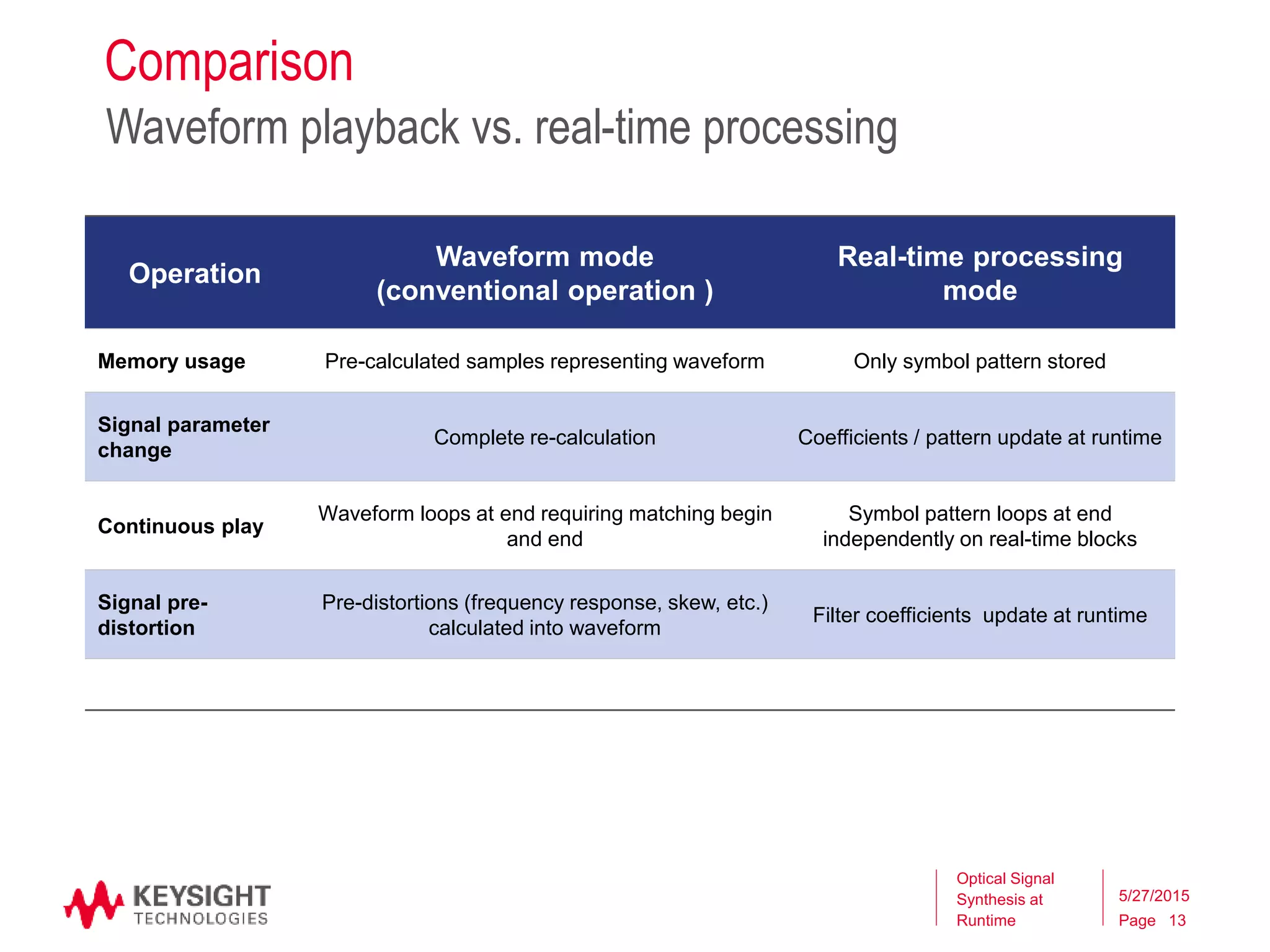
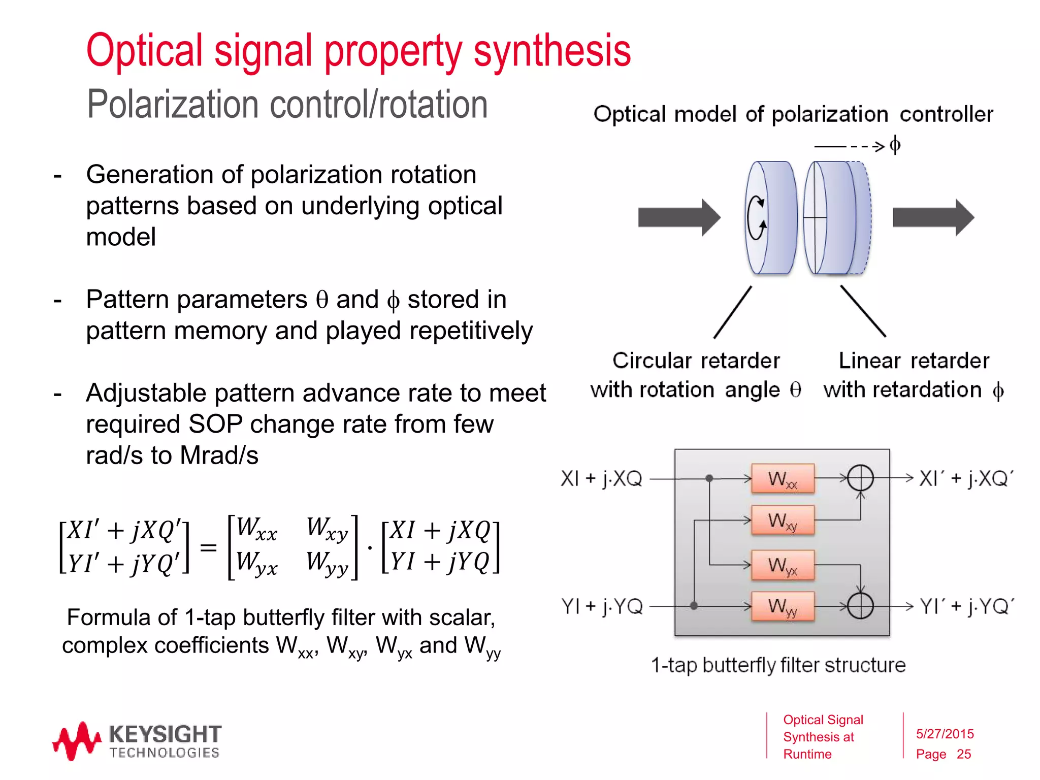
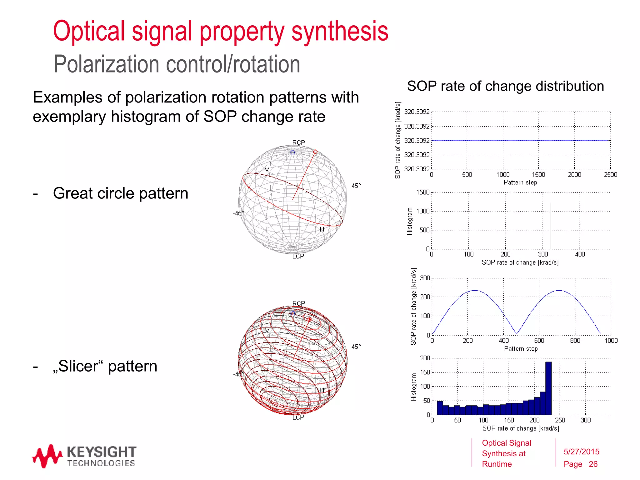
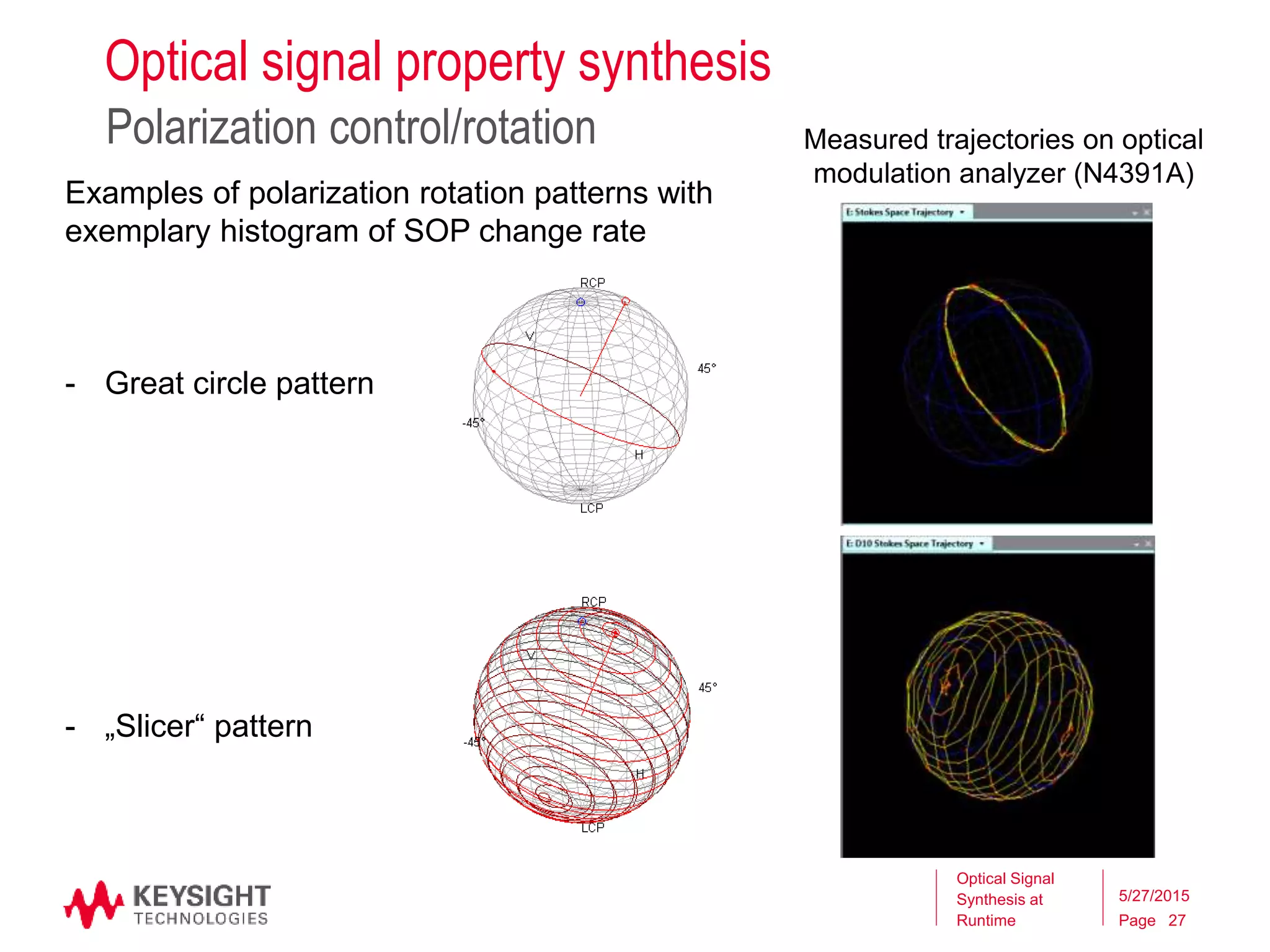
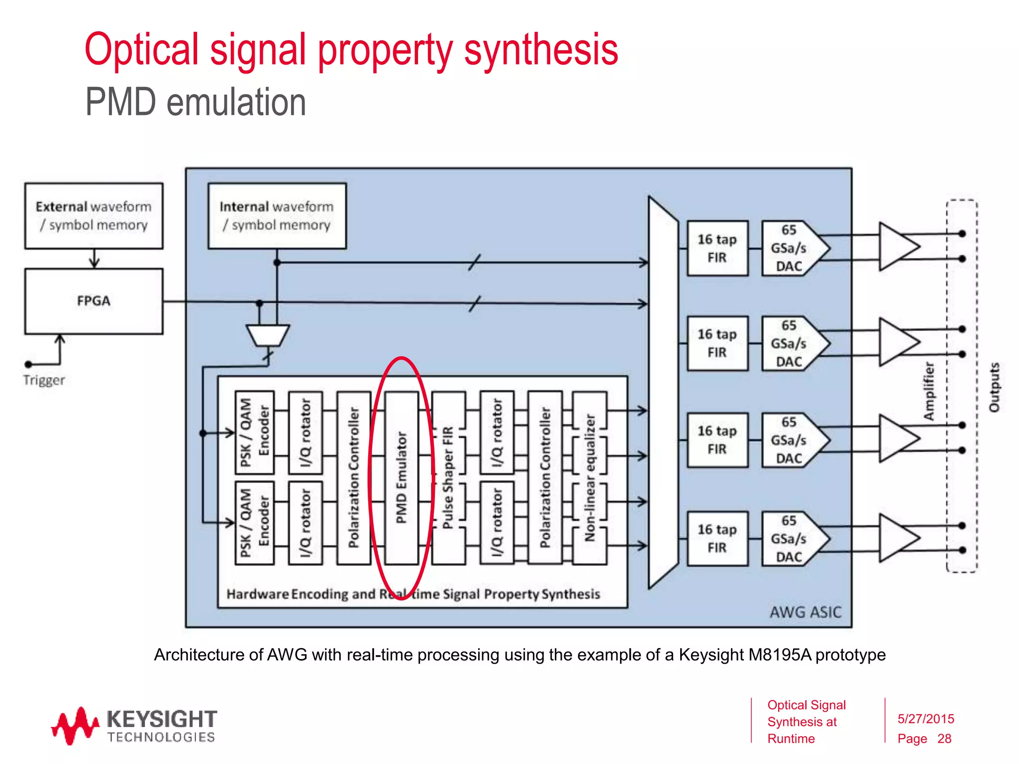
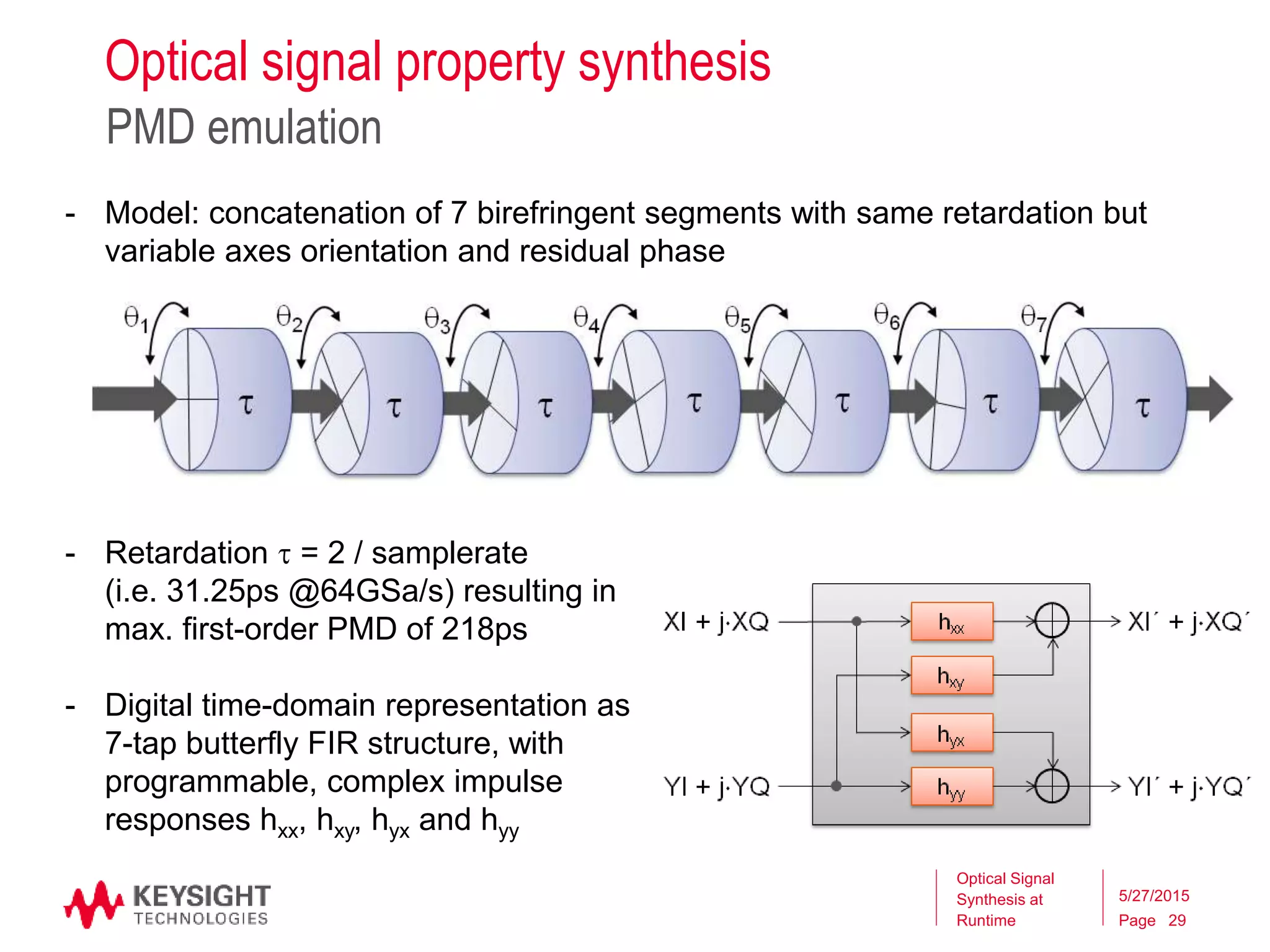
Optical signal property synthesis
PMD emulation
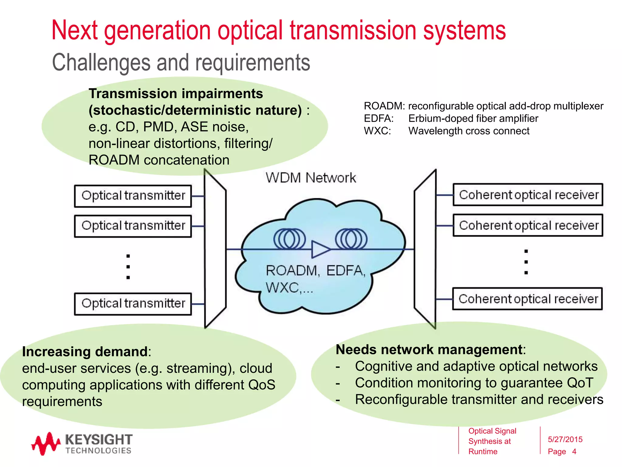
Optical Signal
Synthesis at
Runtime
5/27/2015
30
Addressable PMD space with shown model
at 64GSa/s sampling rate:
• First order PMD: up to 218ps
• Second order PMD: up to 11500ps2
Addressable PMD space
0 20 40 60 80 100 120 140 160 180 200 220
0
2000
4000
6000
8000
10000
12000
First-order PMD [ps]
Second.orderPMD[ps2]
-50 -40 -30 -20 -10 0 10 20 30 40 50
0
50
100
150
200
DGD(ps)
-50 -40 -30 -20 -10 0 10 20 30 40 50
0
5000
10000
SOPMD(ps2)
-50 -40 -30 -20 -10 0 10 20 30 40 50
-4000
-2000
0
2000
4000
Relative frequency (GHz)
PDCD(ps2)
PMD spectra (exemplary settings)
32G channel spectrum
- Red dots: selected states from
7 segment model
- Green dots: selected states
from 6 segment model
- Blue dots: simulated random
states](https://image.slidesharecdn.com/12h30m-keysightcpqdworkshop20151-150601151601-lva1-app6891/75/Optical-Signal-Property-Synthesis-at-Runtime-An-new-approach-for-coherent-transmission-stress-testing-30-2048.jpg)


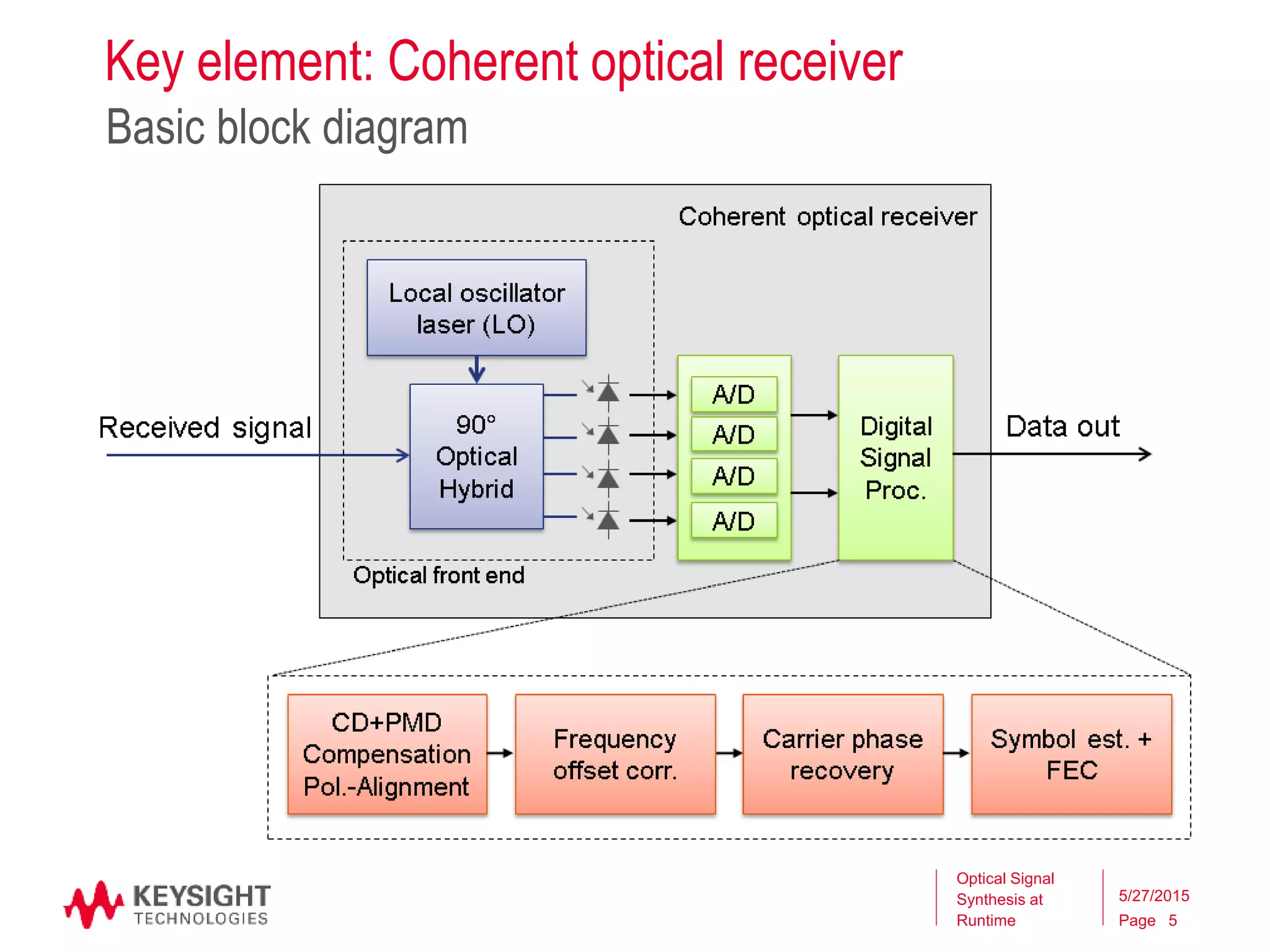
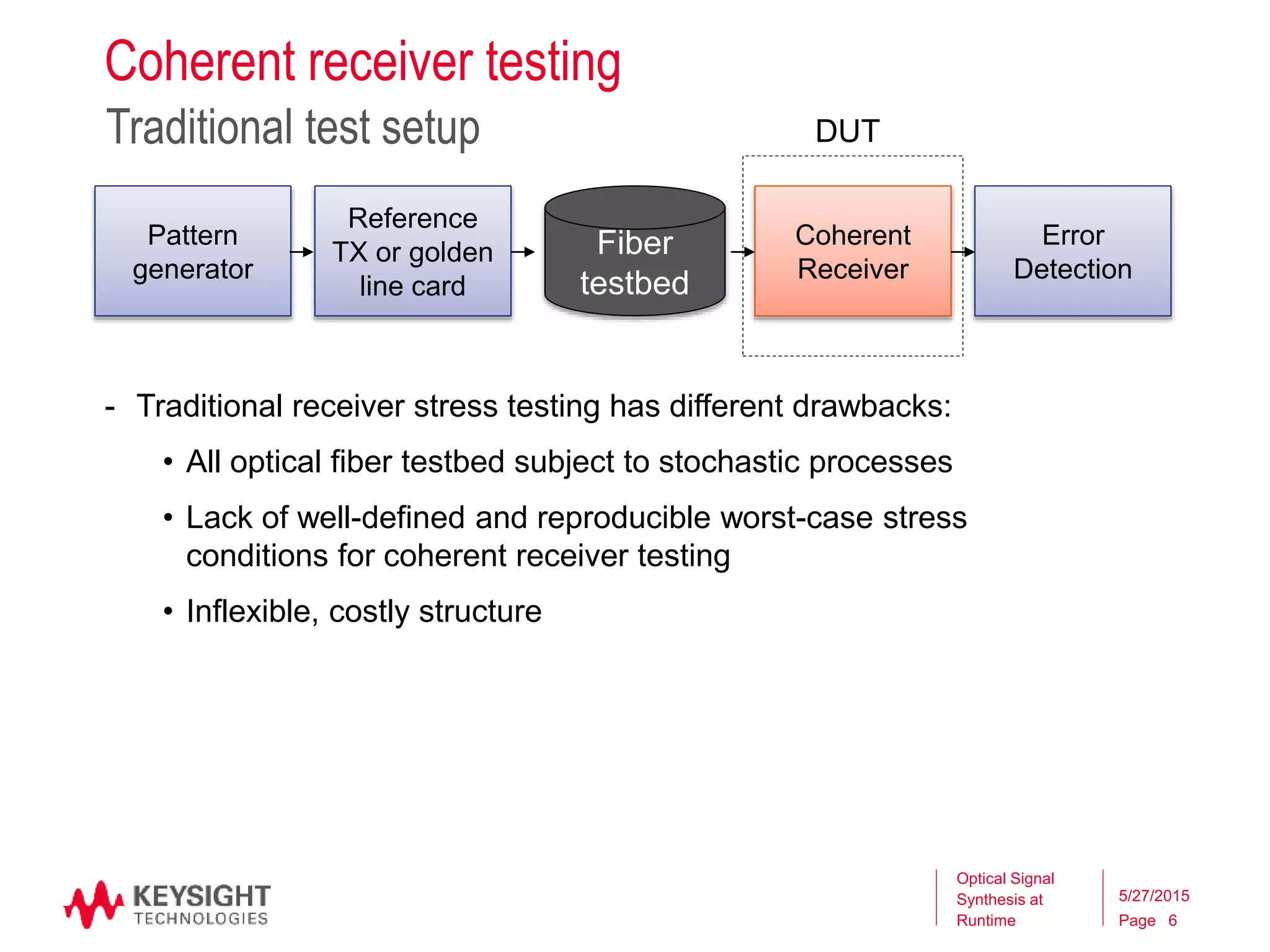
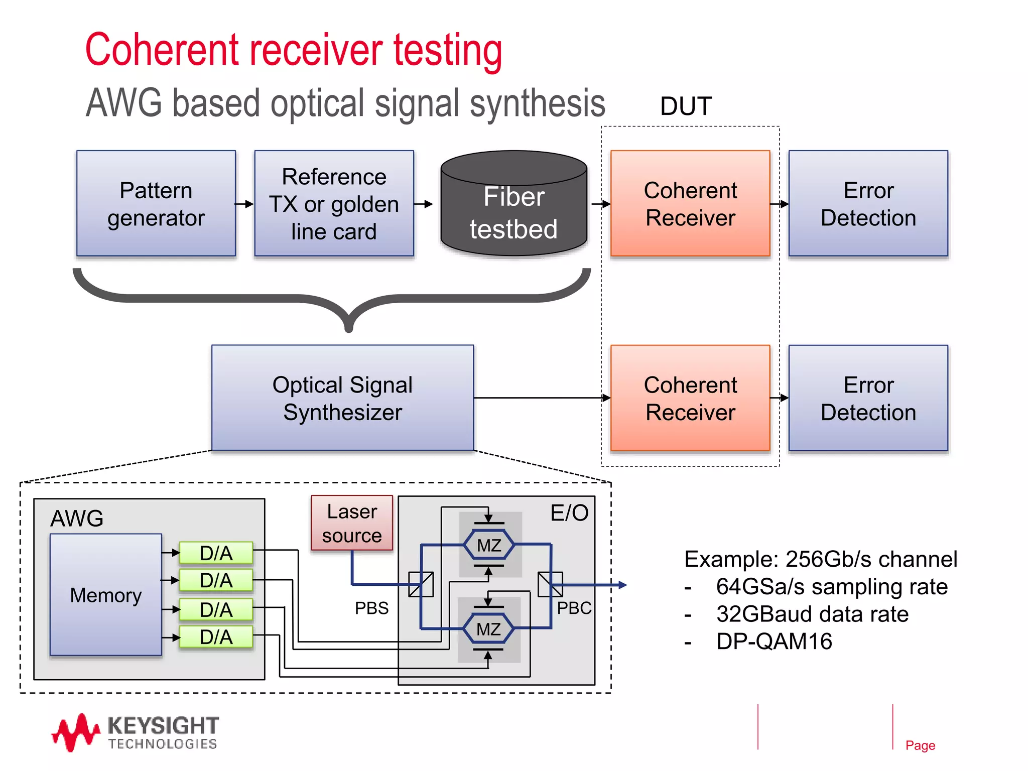
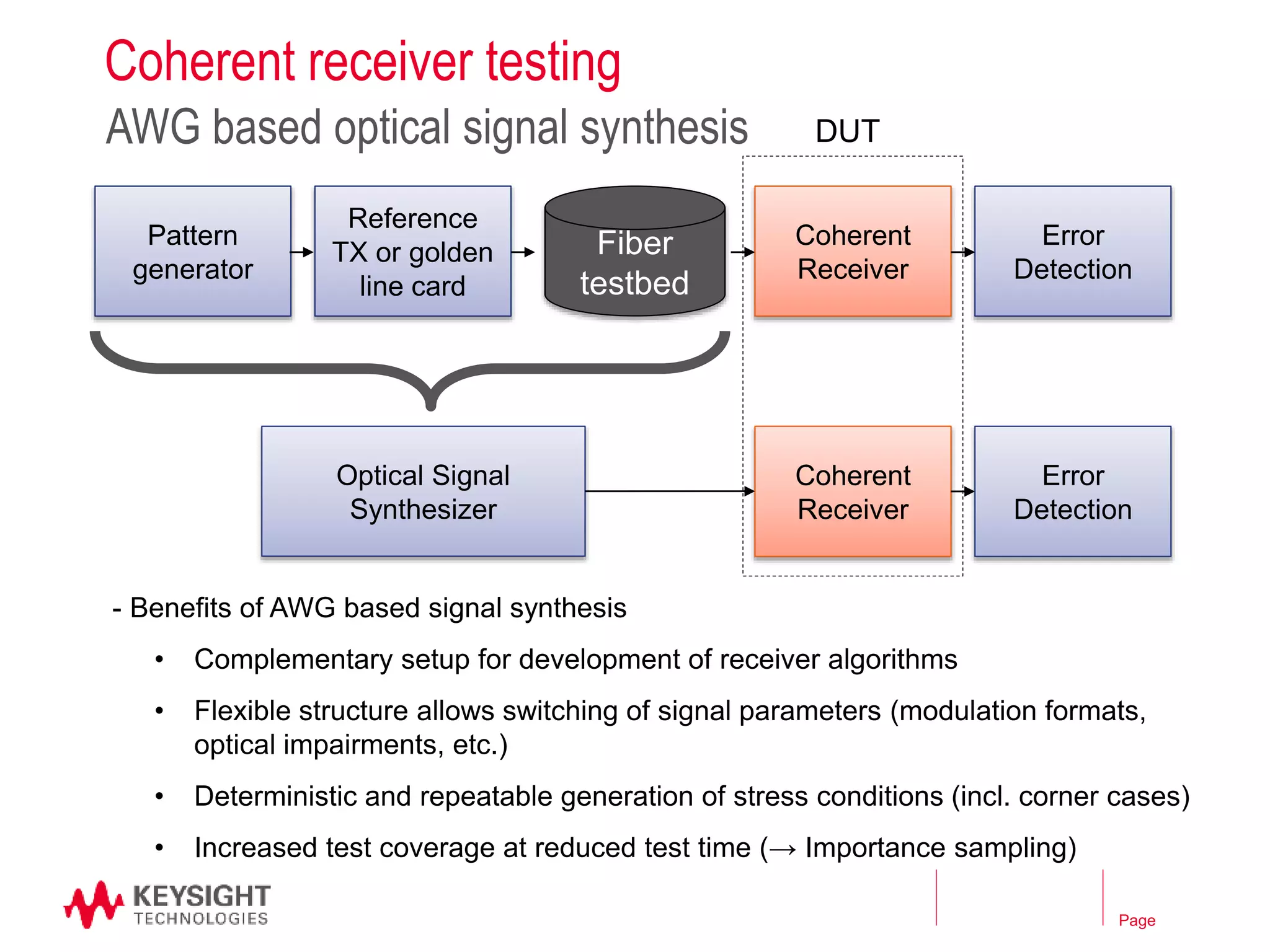
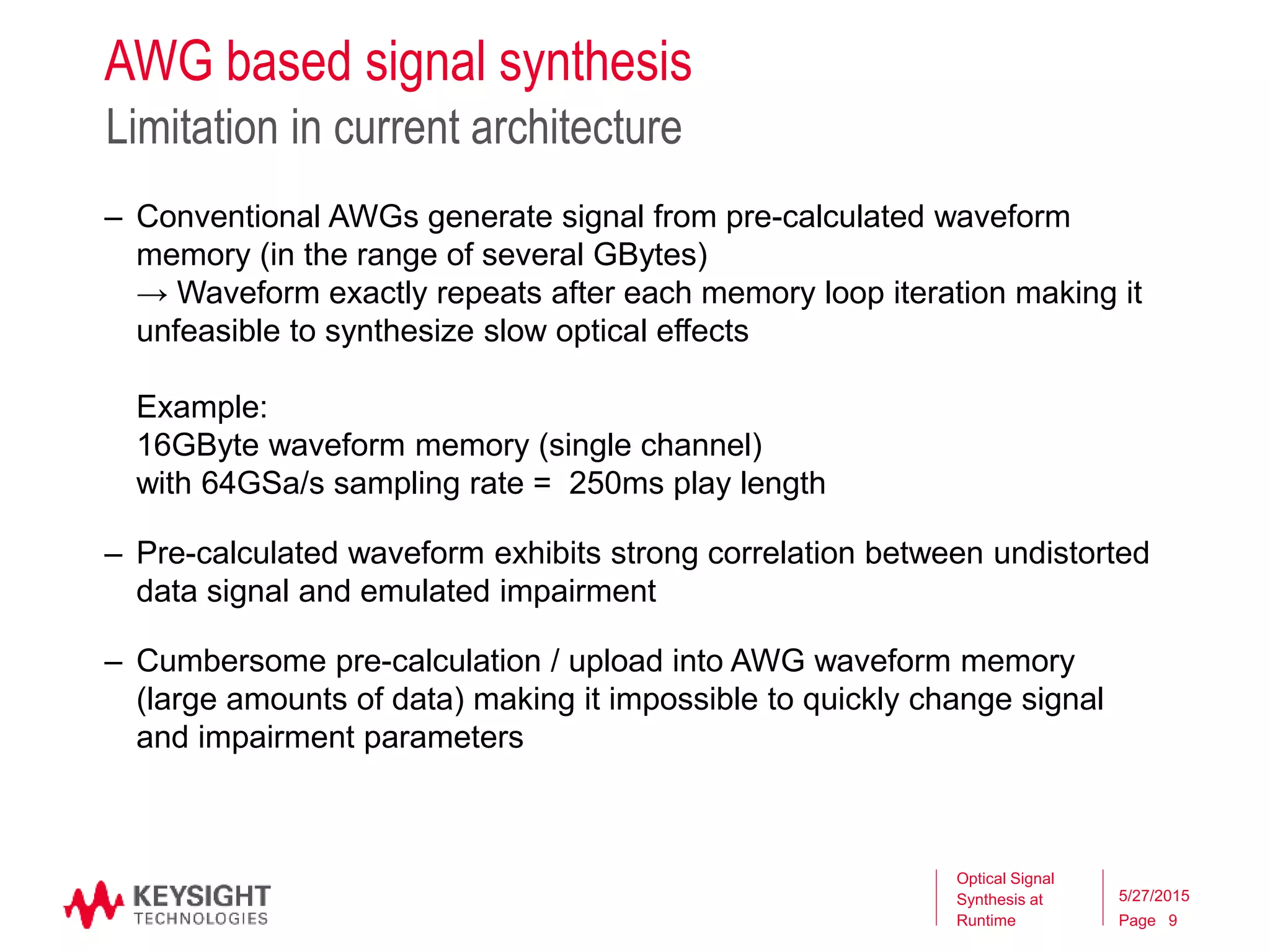
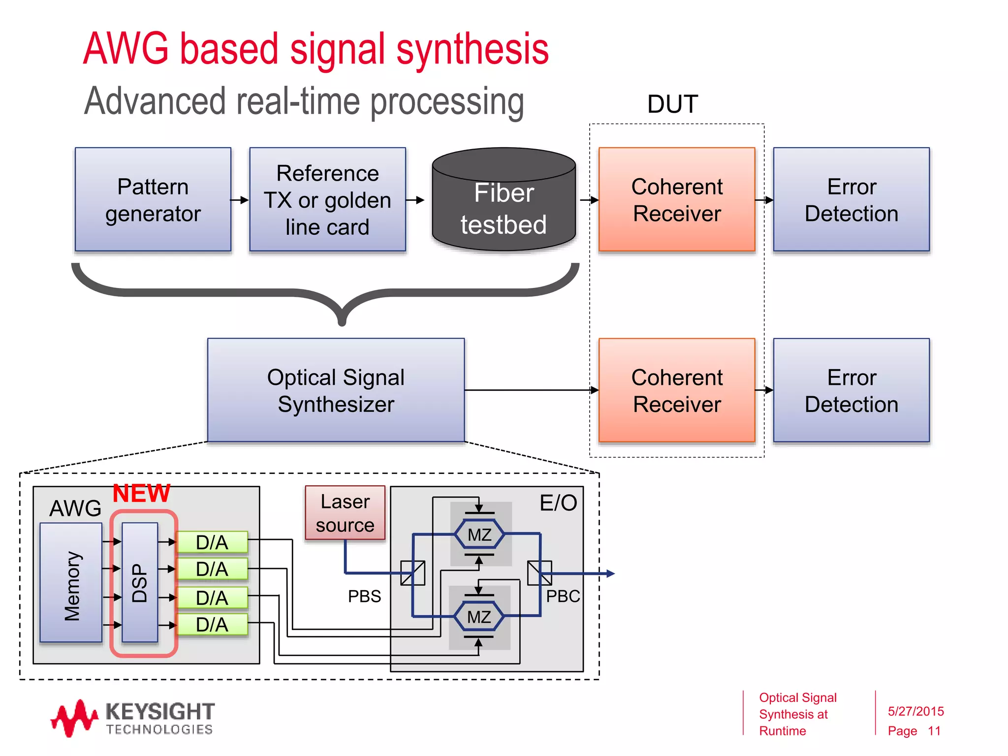
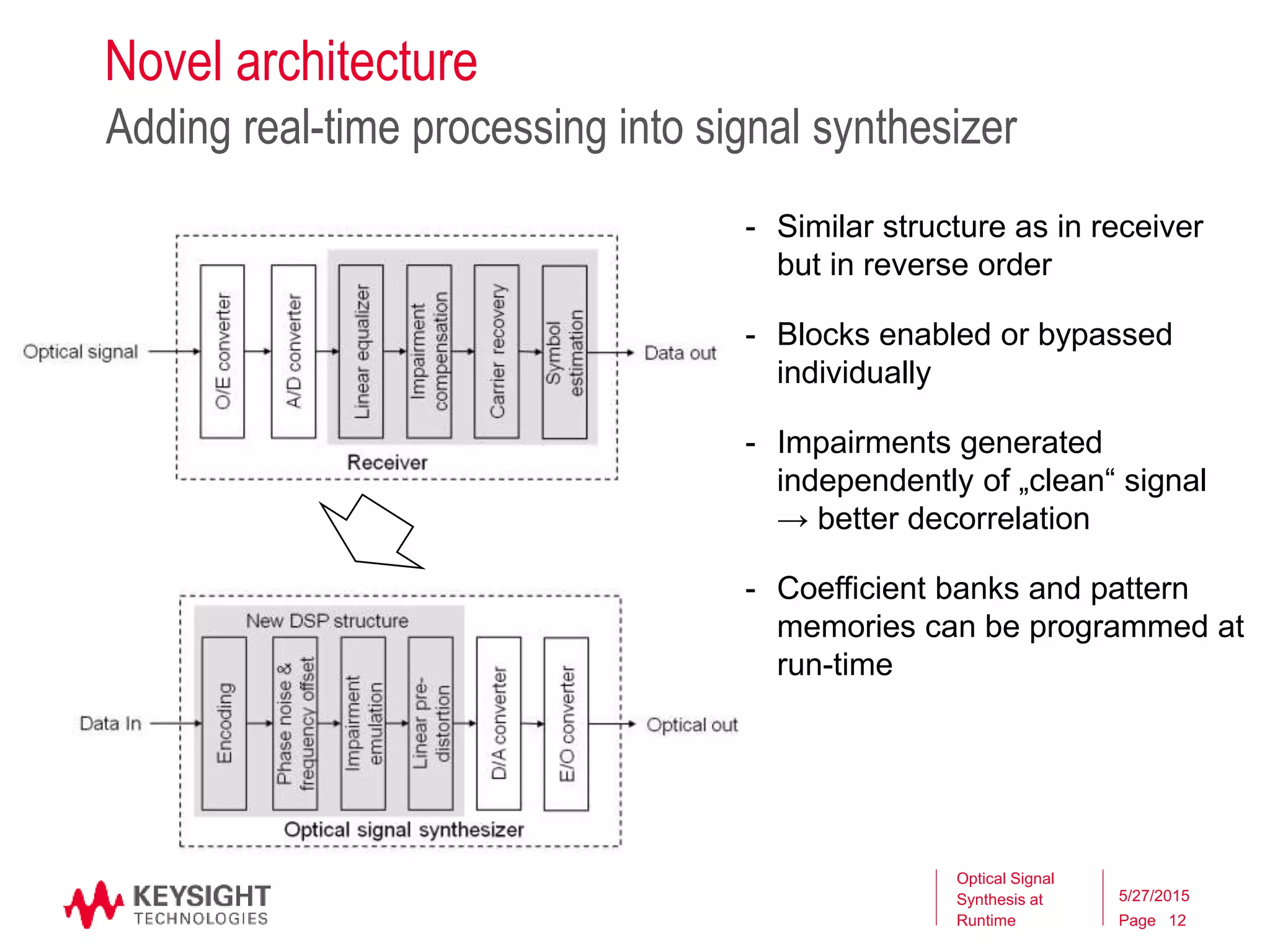
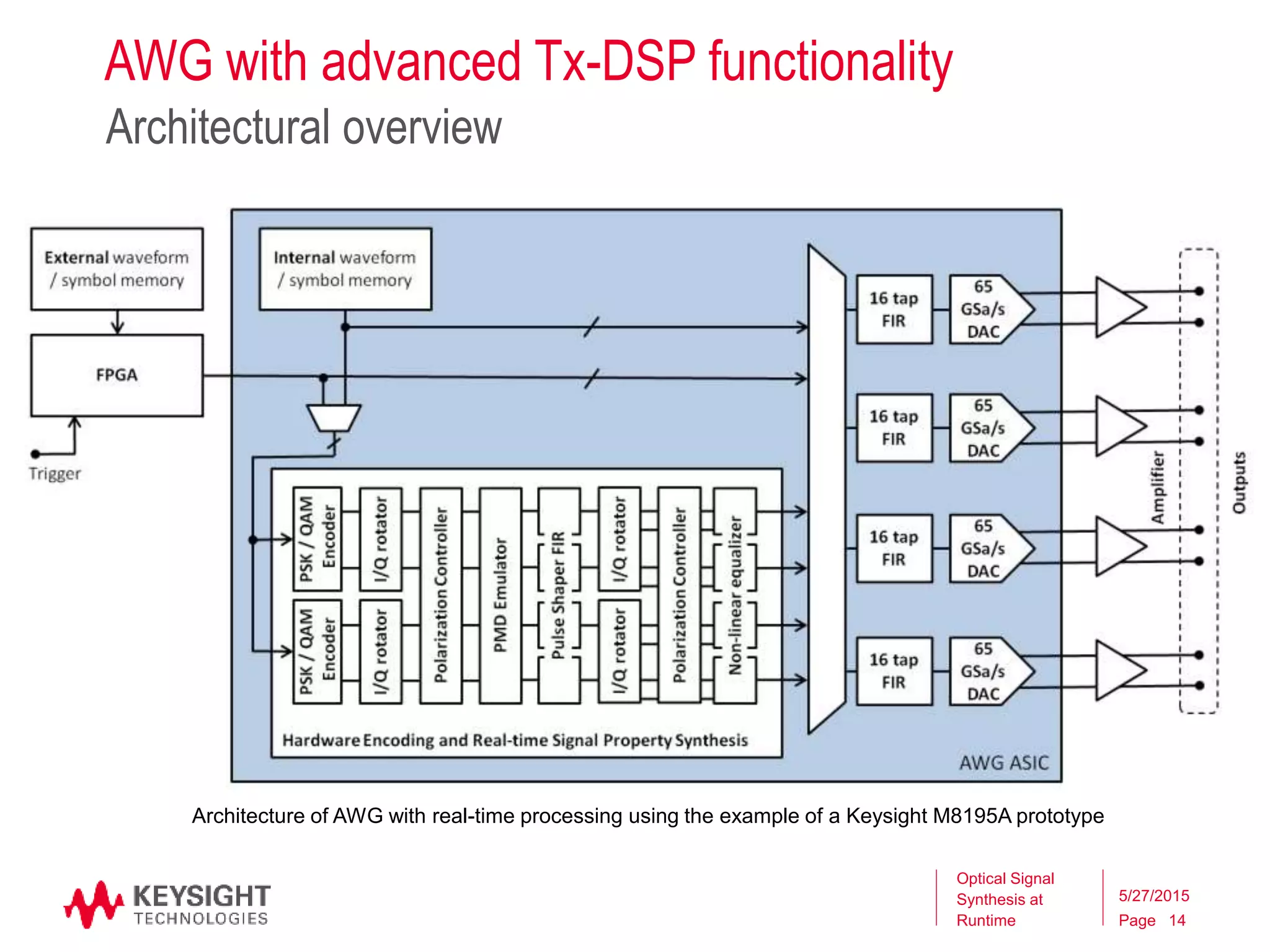
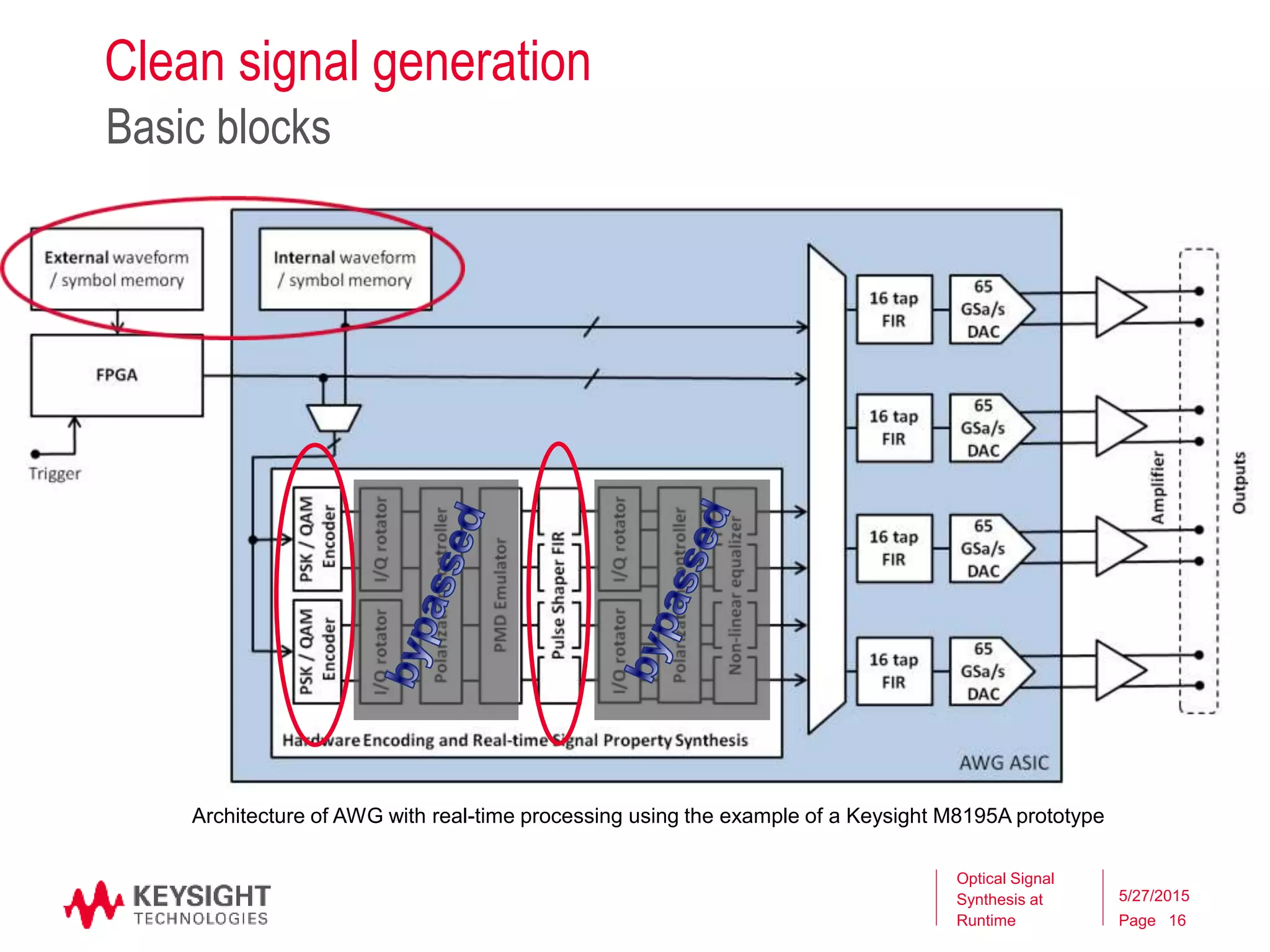
This document describes a new approach for coherent optical receiver stress testing using digital signal processing (DSP) in an arbitrary waveform generator (AWG)-based optical signal synthesizer. The new approach allows for real-time generation and control of optical signal properties like phase noise, polarization, and polarization mode dispersion that overcome limitations of pre-calculating entire waveforms. This provides a flexible test platform for systematically evaluating receivers under worst-case impairment conditions.


![Coded Agents – with UiPath SDK + LangGraph [Virtual Hands-on Workshop]](https://cdn.slidesharecdn.com/ss_thumbnails/codedagentsdeck-251215155422-5497c599-thumbnail.jpg?width=640&height=640&fit=bounds)


