Downloaded 1,053 times


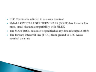


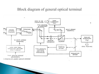
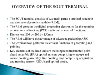
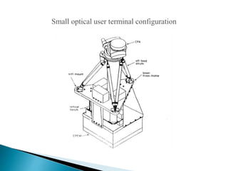


This document summarizes the Small Optical User Terminal (SOUT) designed for optical communication between low Earth orbit and geostationary orbit satellites. The SOUT uses lasers for transmission and reception, with integrated transmitters, fine pointing loops to correct for disturbances, and an optical bench. It is compact in size at 200x200x150mm and has the potential to enable high-capacity intersatellite links with advantages over microwave technologies in terms of mass and power consumption.