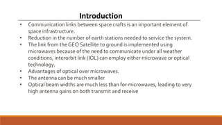
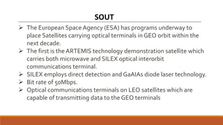
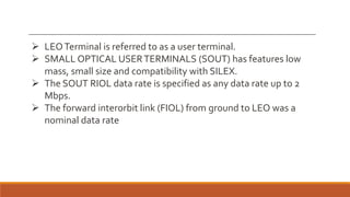
Subject: Computer Network
Presentation On “Optical Satellite Communication”
Submitted To :
Ms. Sapna Kushwah
(Asst. Prof. , Department of
Computer Science & Engineering)
Submitted By :
Bharat Rathore
(0905CS191062)
Activity - 1
OUTLINES
• Introduction
• SOUT
• Link Design
• Generic Optical Terminal
• Optical Antenna
• Integrated Transmitter
• Fine Pointing Loop
• Optical Bench
• Conclusion
Introduction
• Communication links between space crafts is an important element of
space infrastructure.
• Reduction in the number of earth stations needed to service the system.
• The link from the GEO Satellite to ground is implemented using
microwaves because of the need to communicate under all weather
conditions, interorbit link (IOL) can employ either microwave or optical
technology.
• Advantages of optical over microwaves.
• The antenna can be much smaller
• Optical beam widths are much less than for microwaves, leading to very
high antenna gains on both transmit and receive
SOUT
 The European Space Agency (ESA) has programs underway to
place Satellites carrying optical terminals in GEO orbit within the
next decade.
 The first is the ARTEMIS technology demonstration satellite which
carries both microwave and SILEX optical interorbit
communications terminal.
 SILEX employs direct detection and GaAIAs diode laser technology.
 Bit rate of 50Mbps.
 Optical communications terminals on LEO satellites which are
capable of transmitting data to the GEO terminals
 LEOTerminal is referred to as a user terminal.
 SMALL OPTICAL USERTERMINALS (SOUT) has features low
mass, small size and compatibility with SILEX.
 The SOUT RIOL data rate is specified as any data rate up to 2
Mbps.
 The forward interorbit link (FIOL) from ground to LEO was a
nominal data rate
Link Design
• Wavelength and polarization
 Circular polarization is used over the link so that the
power does not depend upon the orientation of the
 The transmit and receive beams inside the terminal
arranged to have orthogonal linear polarization and
separated in wave length.
 The transmit and receive wavelengths are based on
laser diodes.
• Link budgets for an asymmetric link
 Requirements, RIOL data rate must be
 FIOL data rate minimum than RIOL.
 Large telescope diameter at GEO and small
telescope diameter at LEO
 Pointing:- depends on
 accuracy to which one satellite knows the location of the other.
 accuracy to which it knows its own attitude and.
 accuracy to which it can aim its beam knowing the required
 Acquisition
 Before communication can commence, a high power beam laser
LEO end has to scan over the region of uncertainty until it
terminal and is detected.
 Once the GEO terminal receives the LEO communication beam it
from the beacon to the forward link communication beam.
 communication link between the LEO and GEO space craft
 Tracking :-
 In this mode the on-board disturbances which introduce pointing fitter into the
beam are alternated by means of a fine pointing control loop (FPL) to enable
communications to be obtained.
 These disturbances are due to thruster firings, solar arrays drive mechanisms,
harmonics and other effects.
 Point ahead angle:-
 This is needed because of the relative orbital motion between the satellites
transmitted beam to be aimed at a point in space where the receiving terminal
time of arrival of the beam
 point ahead angle= 2Vt /c where
Vt = transverse Velocity component of the satellite.
C = Speed of light
 The use of a geostationary satellite as a relay for permanent links between
low orbit satellites and a network of a small number of earth stations.
 An increase in system capacity by combining the capacities of several
geostationary satellites.
 The planning of systems with a higher degree of flexibility.
 Consideration of systems providing a permanent link and worldwide
coverage.
 using low orbit satellites as an alternative to systems using geostationary
satellites.
 Optical technology is more advantageous in terms of mass and power
consumption for high capacity links.
Following are the Intersatellite links permit
 In this system a nested pair of mechanism which perform the course
pointing and fine pointing functions is used.
 The former is the coarse pointing assembly (CPA) and has a large
angular range but a small band width .
 The latter, the fine pointing assembly (FPA) has a small angular
range and large band width.
 These form elements of control loops in conjunction with acquisition
and tracking sensors which detect the line of sight of the incoming
optical beam
General Optical Terminal
 The optical antenna comprises the telescope and coarse
pointing assembly.
 The telescope is a refractive keplerian design.
 The CPA uses stepping motors together with a conventional
spur gear and planetary gear.
 The total height of the optical antenna is a major contributor
to the height of the CPA
Optical Antenna
• This consists of a prime/redundant pair of laser modules, a
redundancy switch, and a point ahead assembly (PAA)
• Each laser module contains a laser diode, collimating lenses,
cylindrical lens and focusing lens for coupling light into the fiber.
• Coupling efficiency into the fiber is expected to exceed 70%.
• Modulation can be internal or external.
• Internal modulation implies direct modification .
• External modulation is a modification of the light beam after its
emission by the laser.
• he intensity, the frequency, the phase and the polarization can be
modulated. Phase and polarization modulation are external.
Intensity and frequency modulation can be internal or external.
Integrated Transmitter
 The fine pointing loop (FPL) is required to attenuate external
pointing disturbances so that the residual mis point angle is a
small fraction of the optical beam width.
 The closed loop tracking subsystem consists of a tracking sensor.
Fine Pointing Loop
Optical Bench
 The duplexer, quarter wave plate and other lens system, acquisition
and tracking are all placed in the optical bench.
 The duplexer has a dielectric multilayer coating which provides
efficient transmission of one type polarised light at the transmit
wavelength (848 nm) and rejects another type polarised light at the
receive wavelength (800 nm).
 A quarter wave plate (QWP) converts the transmit light to circular
polarization state prior to the telescope.
 The PAA, lasers, and redundancy switching mechanisms are on one
side while the diplexer, receive paths and calibration path are on the
other side of the optical bench.
Conclusion
Optical intersatellite communications promises to become
an important element in future space infrastructure and
considerable development effort is currently underway in
Europe and elsewhere.
Optical satellite communication

Optical satellite communication

  • 1.
    Subject: Computer Network PresentationOn “Optical Satellite Communication” Submitted To : Ms. Sapna Kushwah (Asst. Prof. , Department of Computer Science & Engineering) Submitted By : Bharat Rathore (0905CS191062) Activity - 1
  • 2.
    OUTLINES • Introduction • SOUT •Link Design • Generic Optical Terminal • Optical Antenna • Integrated Transmitter • Fine Pointing Loop • Optical Bench • Conclusion
  • 3.
    Introduction • Communication linksbetween space crafts is an important element of space infrastructure. • Reduction in the number of earth stations needed to service the system. • The link from the GEO Satellite to ground is implemented using microwaves because of the need to communicate under all weather conditions, interorbit link (IOL) can employ either microwave or optical technology. • Advantages of optical over microwaves. • The antenna can be much smaller • Optical beam widths are much less than for microwaves, leading to very high antenna gains on both transmit and receive
  • 4.
    SOUT  The EuropeanSpace Agency (ESA) has programs underway to place Satellites carrying optical terminals in GEO orbit within the next decade.  The first is the ARTEMIS technology demonstration satellite which carries both microwave and SILEX optical interorbit communications terminal.  SILEX employs direct detection and GaAIAs diode laser technology.  Bit rate of 50Mbps.  Optical communications terminals on LEO satellites which are capable of transmitting data to the GEO terminals
  • 5.
     LEOTerminal isreferred to as a user terminal.  SMALL OPTICAL USERTERMINALS (SOUT) has features low mass, small size and compatibility with SILEX.  The SOUT RIOL data rate is specified as any data rate up to 2 Mbps.  The forward interorbit link (FIOL) from ground to LEO was a nominal data rate
  • 6.
    Link Design • Wavelengthand polarization  Circular polarization is used over the link so that the power does not depend upon the orientation of the  The transmit and receive beams inside the terminal arranged to have orthogonal linear polarization and separated in wave length.  The transmit and receive wavelengths are based on laser diodes.
  • 7.
    • Link budgetsfor an asymmetric link  Requirements, RIOL data rate must be  FIOL data rate minimum than RIOL.  Large telescope diameter at GEO and small telescope diameter at LEO
  • 8.
     Pointing:- dependson  accuracy to which one satellite knows the location of the other.  accuracy to which it knows its own attitude and.  accuracy to which it can aim its beam knowing the required  Acquisition  Before communication can commence, a high power beam laser LEO end has to scan over the region of uncertainty until it terminal and is detected.  Once the GEO terminal receives the LEO communication beam it from the beacon to the forward link communication beam.  communication link between the LEO and GEO space craft
  • 9.
     Tracking :- In this mode the on-board disturbances which introduce pointing fitter into the beam are alternated by means of a fine pointing control loop (FPL) to enable communications to be obtained.  These disturbances are due to thruster firings, solar arrays drive mechanisms, harmonics and other effects.  Point ahead angle:-  This is needed because of the relative orbital motion between the satellites transmitted beam to be aimed at a point in space where the receiving terminal time of arrival of the beam  point ahead angle= 2Vt /c where Vt = transverse Velocity component of the satellite. C = Speed of light
  • 10.
     The useof a geostationary satellite as a relay for permanent links between low orbit satellites and a network of a small number of earth stations.  An increase in system capacity by combining the capacities of several geostationary satellites.  The planning of systems with a higher degree of flexibility.  Consideration of systems providing a permanent link and worldwide coverage.  using low orbit satellites as an alternative to systems using geostationary satellites.  Optical technology is more advantageous in terms of mass and power consumption for high capacity links. Following are the Intersatellite links permit
  • 11.
     In thissystem a nested pair of mechanism which perform the course pointing and fine pointing functions is used.  The former is the coarse pointing assembly (CPA) and has a large angular range but a small band width .  The latter, the fine pointing assembly (FPA) has a small angular range and large band width.  These form elements of control loops in conjunction with acquisition and tracking sensors which detect the line of sight of the incoming optical beam General Optical Terminal
  • 12.
     The opticalantenna comprises the telescope and coarse pointing assembly.  The telescope is a refractive keplerian design.  The CPA uses stepping motors together with a conventional spur gear and planetary gear.  The total height of the optical antenna is a major contributor to the height of the CPA Optical Antenna
  • 13.
    • This consistsof a prime/redundant pair of laser modules, a redundancy switch, and a point ahead assembly (PAA) • Each laser module contains a laser diode, collimating lenses, cylindrical lens and focusing lens for coupling light into the fiber. • Coupling efficiency into the fiber is expected to exceed 70%. • Modulation can be internal or external. • Internal modulation implies direct modification . • External modulation is a modification of the light beam after its emission by the laser. • he intensity, the frequency, the phase and the polarization can be modulated. Phase and polarization modulation are external. Intensity and frequency modulation can be internal or external. Integrated Transmitter
  • 14.
     The finepointing loop (FPL) is required to attenuate external pointing disturbances so that the residual mis point angle is a small fraction of the optical beam width.  The closed loop tracking subsystem consists of a tracking sensor. Fine Pointing Loop
  • 15.
    Optical Bench  Theduplexer, quarter wave plate and other lens system, acquisition and tracking are all placed in the optical bench.  The duplexer has a dielectric multilayer coating which provides efficient transmission of one type polarised light at the transmit wavelength (848 nm) and rejects another type polarised light at the receive wavelength (800 nm).  A quarter wave plate (QWP) converts the transmit light to circular polarization state prior to the telescope.  The PAA, lasers, and redundancy switching mechanisms are on one side while the diplexer, receive paths and calibration path are on the other side of the optical bench.
  • 16.
    Conclusion Optical intersatellite communicationspromises to become an important element in future space infrastructure and considerable development effort is currently underway in Europe and elsewhere.