Download to read offline


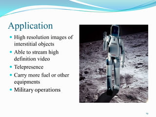


The document discusses the Laser Communications Relay Demonstration (LCRD) project between NASA and MIT Lincoln Laboratory to demonstrate high-data rate optical communications from space. The LCRD flight payload includes an optical module, modem, and electronics to transmit and receive laser signals. The payload will use differential phase-shift keying (DPSK) for near-Earth missions and pulse-position modulation (PPM) for deep-space. The LCRD ground segment consists of two ground stations and a mission operations center to coordinate activities. The goals are to advance optical communication technologies to provide higher bandwidth capabilities with lower mass, power and volume requirements.