Downloaded 241 times
![REPORT
Optical Fibers in
Communications
[2011]
SUBMITTED BY
GURU VASHIST
0830531011
E.C. VII SEM
ARYABHATT COLLEGE OF ENGINEERING AND TECHNOLOGY](https://image.slidesharecdn.com/guruvashistreport-111004125008-phpapp02/85/Guru-vashist-report-1-320.jpg)
![REPORT
Optical Fibers in
Communications
[2011]
SUBMITTED BY
GURU VASHIST
0830531011
E.C. VII SEM
ARYABHATT COLLEGE OF ENGINEERING AND TECHNOLOGY](https://image.slidesharecdn.com/guruvashistreport-111004125008-phpapp02/75/Guru-vashist-report-1-2048.jpg)
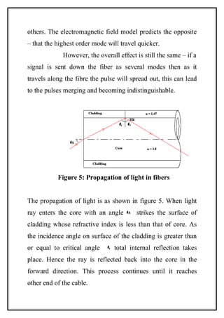
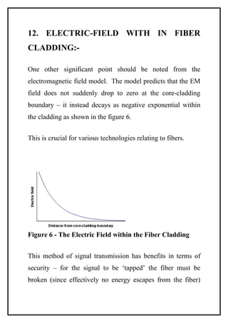
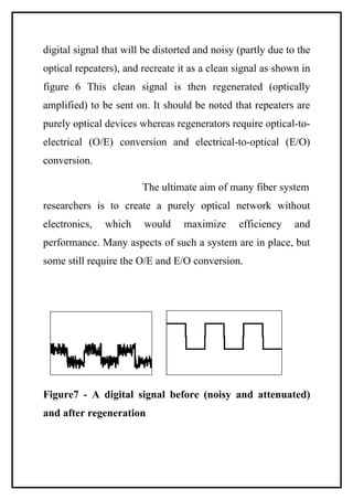


This document provides an overview of optical fibers used in communication systems. It discusses the history of optical fiber communication and how total internal reflection allows light to propagate along the fiber. The key components of an optical fiber are the core and cladding. Optical fibers can be classified based on the materials used, number of modes supported, and refractive index profile. Optical fibers play an important role in modern communication systems by providing high bandwidth data transmission over long distances.


