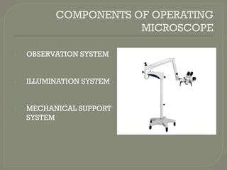
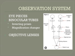
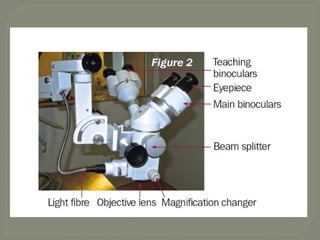
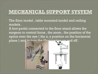
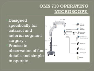
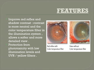
OPERATING
MICROSCOPE
DR.TANUJA RANA
JR – 1 OPHTHALMOLOGY
HISTORY
 The title of “ Father of
Ophthalmic microsurgery”
goes to Dr. Richard A
Perritt .
 The first ophthalmologist ,
on record to use a
microscope in ocular
surgery at around 1946 .
INTRODUCTION
 Single most important equipment without which
the present day modern eye surgery is
impossible .
 Minimum demands for a magnifying system are
formation of enlarged , upright and unreversed
image .
 These conditions are fulfilled by prism binocular
loupes .
 But for increasing sophistication of
microsurgical techniques and instrumentation
additional features are desirable that are
available in modern operating microscope .
COMPONENTS OF OPERATING
MICROSCOPE
1. OBSERVATION SYSTEM
2. ILLUMINATION SYSTEM
3. MECHANICAL SUPPORT
SYSTEM
OBSERVATION SYSTEM
1. EYE PIECES
2. BINOCULAR TUBES
• Inverting prism
• Magnification changer
3. OBJECTIVE LENSES
EYE PIECES
 Act as main magnifiers.
 However, total magnification of
the operating microscope is
equal to the product of the
magnification of various
components of observation
system.
 Different magnifications – 10X,
12.5X, 16X and 20X.
BINOCULAR TUBES
 It can be straight, inclined or
can be tilted to any angle
 For comfartble view, inclined
tubes are prefered
 Tube lenses come in two focal
lenghts : 125 mm and 160 mm
 Tube lens plus objective lens
forms the image of the object at
the focal plane of eye pieces
 Main function is to maintain a
suitable distance between the
eyes of the surgeon and the
operating field
 The binocular tubes are consists of:
A. Inverting prism system, such as a Porro-Abbe prism, it
corrects the inverted image produced by the eyepiece
B. Magnification changer are incorporated into the
operating microscope to get the required variable
magnification of the image
Two types of magnification changer system are
available:
a) Galilean step magnification changer
b) Zoom magnification changer
Galilean Magnification Changer
 Utilizes Galilean telescope to alter the
magnification
 It has two optical components – positive
lens and negative lens
 Incorporates two telescopes – one with
magnification of 2.5X and another with
1.6X.
 When there optical components are
reversed, they cause minification of image
by 0.4X and 0.63X respectively.
 There is one free path that gives
magnification of 1X. So, the magnification
changer can magnify 0.4, 0.63, 1.0, 1.6 and
2.5 times.
Zoom magnification changer
Most advanced and very comfortable,
which can be opeated by a foot control
panel
It provides continuous change in
magnification ranging from 0.5X to 2.5X.
Manufacturing is more difficult ,so its
expensive.
OBJECTIVE LENS
 The working distance of the microscope
is equal to focal length of the objective
lens.
 Commonly used objective focal lengths
are 150, 175 and 200 mm.
 A proper working distance can greatly
lessen strain, especially during lengthy
operation.
 Focal length selected should be
sufficiently long so that the microscope
doesn’t interfere with the surgeons
instrument yet sufficiently short so that
the operation is not performed at arms
length.
MAGNIFICATION
 Magnification of the simple microscope
depends upon the objective lens, tube lens and
eyepiece lens.
 Total magnification = Ft/Fo x Ve
Ft= tube lens focal length
Fo= objective lens focal length
Ve= magnification due to eyepieces
 Since the magnification changer is nowadays
incorporated in the body of microscope hence
the magnification can be changed.
 Total magnication = Ft/Fo x Ve x Magnification
factor
FIELD OF VIEW
It is determined by the total
magnification used.
More the magnification used, less is the
field of vision.
Field of view = Fo/Ve
ILLUMINATION SYSTEM
The illumination system is usually housed
in the floor stand in order to keep the
bulb heat away from the operating field .
The light is transmitted to the operating
field by means of a fibre optic cable.
The light in ophthalmic microscopes is
usually coaxial , meaning that it follows
the same path as the image in order to
avoid shadows .
 Previously , Incandescent lamps were used as
a source of light .
 They emit a maximum of only about 4% of the
electrical energy as visible light .
 Most of the energy emission is infrared light
which is the heat radiation and invisible to
human eye .
 Do not comply with the high demands of
documentation equipment like video
recording.
 Halogen lamps are being preferred now .
 Halogen lamps ( 12 V , 1000 W) are falsely termed
as “ cool light illuminators .
 Like incandescent lamps , they also produce a lot
of heat and are more sensitive to voltage
fluctuations .
 Have longer average life than incandescent
lamps .
 They emit light of high color temperature which
has high percentage of blue light which increases
the contrast of the objects .
MECHANICAL SUPPORT SYSTEM
 The floor model , table mounted model and ceiling
models .
 A foot pedal connected to the floor stand allows the
surgeon to control focus , the zoom , the position of the
optics over the eye ( the x, y position on the horizontal
plane ) and to turn the illumination on and off .
OMS 710 OPERATING
MICROSCOPE
Designed
specifically for
cataract and
anterior segment
surgery .
Precise in
observation of fine
details and simple
to operate .
FEATURES
 Improve red reflex and
shadow contrast : contrast
is more neutral and the
color temperature filter in
the illumination system ,
allows a softer and more
detailed view .
 Protection from
phototoxicity with low
illumination levels and
UVR / yellow filters .
PHOTOTOXICITY FROM UV
RADIATIONS
 Hazards from the optical radiation of an operating
microscope can cause damage at the corneal,
lenticular, and retinal levels.
 Safe exposure time to avoid UVR injury to the lens
and cornea was found to be 2 hours without a filter,
4 hours with the UVR filter, 200 hours with a yellow
filter and 400 hours with the filter combination.
 Safe exposure time to avoid was found to be 3 min
without a filter and with a UVR filter, 10 mins with a
yellow filter and 49 min with a filter combination
FEATURES
 COMPACT BODY:The
OMS-710’s compact base
and longer arms allow
easy mobility and storage
in limited space.
 27% lighter than its
predecessors, making it
easier to install and
simple to maneuver in the
operating room
XY Translator: the precise and smooth
movement of the XY translator provides
the surgeon with control and ease of use.
Touch panel LCD monitor: a
sophisticated touch screen LCD monitor
allows for a quick and easy change of
settings and programs.
 Rotating assistant microscope:
the assistant microscope easily
swings from one side to the
other, pivoting comfort, flexibility
and convenience.
 Main microscope binoculars: two
types of binocular are available
• 45 degree fix set of binoculars.
• A variable inclination set of binoculars,
adjustable from 45 degree to 90 degree,
providing a more comfortable
observation image
Compact TV relay lens: it allows to
connect ½ inch and 1/3 inch CCD
cameras either with a C-mount or SONY-2
mount
Coaxial binocular observation tube: it
provides the same view as the
observation tube of the surgeon and is
useful for education and teaching
purposes. Easy to position and simple to
adjust
OMS 800
 It allows the surgeon to
visualise as far as the ora
serrata for vitreoretinal
surgery, while maintaining
clear and precise detail
throughout the surgical
field.
 Anti-stain coating lens:
optical components remain
clean and maintain its
quality for longer time.
 By using 3 direction illumination system,
the OMS-800 provides an improved red
reflex with better shadow and contrast
even in low illumination conditions.
CARING for the OPERATING
MICROSCOPE
 Keep the microscope in a dry, cool and a well ventilated
place to prevent fungus growth on the optics (lenses).
 To protect it from dust when not in use, drape a cover over
the microscope.
 Wipe down the external surfaces with a damp cloth soaked
in hot, soapy water.
 Cover the foot pedal with a clear plastic bag to prevent
surgical and cleaning fluids from entering and damaging
the electronics.
 Use a voltage stabilizer with the microscope.This will
prevent sudden increase in voltage from destroying the
bulbs and will ensure that the illumination provided remains
constant.
 Before using test the control of the foot pedal
( the x,y movement , zoom, focus, light on and
off)
 Before using check that the susspension arm can
be fixed into position to ensure that it does not
fall on the patient.
 Avoid kinking or bending the fibre optic cables.
 When replacing the bulbs, avoid touching them
with your fingers.The oil left as fingerprints on
the bulb can shorten its life.
 Do not move the microscope while the bulb is
still hot because strong vibrations may damage
the filament.
THANKYOU

OPERATING MICROSCOPE in ophthalmology ot.pptx

  • 1.
  • 2.
    HISTORY  The titleof “ Father of Ophthalmic microsurgery” goes to Dr. Richard A Perritt .  The first ophthalmologist , on record to use a microscope in ocular surgery at around 1946 .
  • 3.
    INTRODUCTION  Single mostimportant equipment without which the present day modern eye surgery is impossible .  Minimum demands for a magnifying system are formation of enlarged , upright and unreversed image .  These conditions are fulfilled by prism binocular loupes .  But for increasing sophistication of microsurgical techniques and instrumentation additional features are desirable that are available in modern operating microscope .
  • 4.
    COMPONENTS OF OPERATING MICROSCOPE 1.OBSERVATION SYSTEM 2. ILLUMINATION SYSTEM 3. MECHANICAL SUPPORT SYSTEM
  • 5.
    OBSERVATION SYSTEM 1. EYEPIECES 2. BINOCULAR TUBES • Inverting prism • Magnification changer 3. OBJECTIVE LENSES
  • 7.
    EYE PIECES  Actas main magnifiers.  However, total magnification of the operating microscope is equal to the product of the magnification of various components of observation system.  Different magnifications – 10X, 12.5X, 16X and 20X.
  • 8.
    BINOCULAR TUBES  Itcan be straight, inclined or can be tilted to any angle  For comfartble view, inclined tubes are prefered  Tube lenses come in two focal lenghts : 125 mm and 160 mm  Tube lens plus objective lens forms the image of the object at the focal plane of eye pieces  Main function is to maintain a suitable distance between the eyes of the surgeon and the operating field
  • 9.
     The binoculartubes are consists of: A. Inverting prism system, such as a Porro-Abbe prism, it corrects the inverted image produced by the eyepiece B. Magnification changer are incorporated into the operating microscope to get the required variable magnification of the image Two types of magnification changer system are available: a) Galilean step magnification changer b) Zoom magnification changer
  • 10.
    Galilean Magnification Changer Utilizes Galilean telescope to alter the magnification  It has two optical components – positive lens and negative lens  Incorporates two telescopes – one with magnification of 2.5X and another with 1.6X.  When there optical components are reversed, they cause minification of image by 0.4X and 0.63X respectively.  There is one free path that gives magnification of 1X. So, the magnification changer can magnify 0.4, 0.63, 1.0, 1.6 and 2.5 times.
  • 11.
    Zoom magnification changer Mostadvanced and very comfortable, which can be opeated by a foot control panel It provides continuous change in magnification ranging from 0.5X to 2.5X. Manufacturing is more difficult ,so its expensive.
  • 12.
    OBJECTIVE LENS  Theworking distance of the microscope is equal to focal length of the objective lens.  Commonly used objective focal lengths are 150, 175 and 200 mm.  A proper working distance can greatly lessen strain, especially during lengthy operation.  Focal length selected should be sufficiently long so that the microscope doesn’t interfere with the surgeons instrument yet sufficiently short so that the operation is not performed at arms length.
  • 13.
    MAGNIFICATION  Magnification ofthe simple microscope depends upon the objective lens, tube lens and eyepiece lens.  Total magnification = Ft/Fo x Ve Ft= tube lens focal length Fo= objective lens focal length Ve= magnification due to eyepieces  Since the magnification changer is nowadays incorporated in the body of microscope hence the magnification can be changed.  Total magnication = Ft/Fo x Ve x Magnification factor
  • 14.
    FIELD OF VIEW Itis determined by the total magnification used. More the magnification used, less is the field of vision. Field of view = Fo/Ve
  • 15.
    ILLUMINATION SYSTEM The illuminationsystem is usually housed in the floor stand in order to keep the bulb heat away from the operating field . The light is transmitted to the operating field by means of a fibre optic cable. The light in ophthalmic microscopes is usually coaxial , meaning that it follows the same path as the image in order to avoid shadows .
  • 16.
     Previously ,Incandescent lamps were used as a source of light .  They emit a maximum of only about 4% of the electrical energy as visible light .  Most of the energy emission is infrared light which is the heat radiation and invisible to human eye .  Do not comply with the high demands of documentation equipment like video recording.
  • 17.
     Halogen lampsare being preferred now .  Halogen lamps ( 12 V , 1000 W) are falsely termed as “ cool light illuminators .  Like incandescent lamps , they also produce a lot of heat and are more sensitive to voltage fluctuations .  Have longer average life than incandescent lamps .  They emit light of high color temperature which has high percentage of blue light which increases the contrast of the objects .
  • 18.
    MECHANICAL SUPPORT SYSTEM The floor model , table mounted model and ceiling models .  A foot pedal connected to the floor stand allows the surgeon to control focus , the zoom , the position of the optics over the eye ( the x, y position on the horizontal plane ) and to turn the illumination on and off .
  • 19.
    OMS 710 OPERATING MICROSCOPE Designed specificallyfor cataract and anterior segment surgery . Precise in observation of fine details and simple to operate .
  • 20.
    FEATURES  Improve redreflex and shadow contrast : contrast is more neutral and the color temperature filter in the illumination system , allows a softer and more detailed view .  Protection from phototoxicity with low illumination levels and UVR / yellow filters .
  • 21.
    PHOTOTOXICITY FROM UV RADIATIONS Hazards from the optical radiation of an operating microscope can cause damage at the corneal, lenticular, and retinal levels.  Safe exposure time to avoid UVR injury to the lens and cornea was found to be 2 hours without a filter, 4 hours with the UVR filter, 200 hours with a yellow filter and 400 hours with the filter combination.  Safe exposure time to avoid was found to be 3 min without a filter and with a UVR filter, 10 mins with a yellow filter and 49 min with a filter combination
  • 22.
    FEATURES  COMPACT BODY:The OMS-710’scompact base and longer arms allow easy mobility and storage in limited space.  27% lighter than its predecessors, making it easier to install and simple to maneuver in the operating room
  • 23.
    XY Translator: theprecise and smooth movement of the XY translator provides the surgeon with control and ease of use. Touch panel LCD monitor: a sophisticated touch screen LCD monitor allows for a quick and easy change of settings and programs.
  • 24.
     Rotating assistantmicroscope: the assistant microscope easily swings from one side to the other, pivoting comfort, flexibility and convenience.  Main microscope binoculars: two types of binocular are available • 45 degree fix set of binoculars. • A variable inclination set of binoculars, adjustable from 45 degree to 90 degree, providing a more comfortable observation image
  • 25.
    Compact TV relaylens: it allows to connect ½ inch and 1/3 inch CCD cameras either with a C-mount or SONY-2 mount Coaxial binocular observation tube: it provides the same view as the observation tube of the surgeon and is useful for education and teaching purposes. Easy to position and simple to adjust
  • 26.
    OMS 800  Itallows the surgeon to visualise as far as the ora serrata for vitreoretinal surgery, while maintaining clear and precise detail throughout the surgical field.  Anti-stain coating lens: optical components remain clean and maintain its quality for longer time.
  • 27.
     By using3 direction illumination system, the OMS-800 provides an improved red reflex with better shadow and contrast even in low illumination conditions.
  • 29.
    CARING for theOPERATING MICROSCOPE  Keep the microscope in a dry, cool and a well ventilated place to prevent fungus growth on the optics (lenses).  To protect it from dust when not in use, drape a cover over the microscope.  Wipe down the external surfaces with a damp cloth soaked in hot, soapy water.  Cover the foot pedal with a clear plastic bag to prevent surgical and cleaning fluids from entering and damaging the electronics.  Use a voltage stabilizer with the microscope.This will prevent sudden increase in voltage from destroying the bulbs and will ensure that the illumination provided remains constant.
  • 30.
     Before usingtest the control of the foot pedal ( the x,y movement , zoom, focus, light on and off)  Before using check that the susspension arm can be fixed into position to ensure that it does not fall on the patient.  Avoid kinking or bending the fibre optic cables.  When replacing the bulbs, avoid touching them with your fingers.The oil left as fingerprints on the bulb can shorten its life.  Do not move the microscope while the bulb is still hot because strong vibrations may damage the filament.
  • 31.