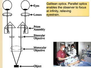
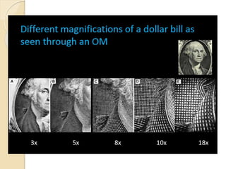
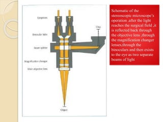
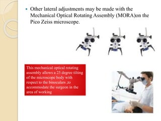
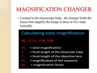
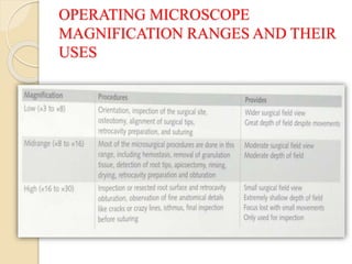
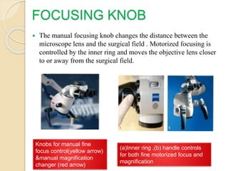
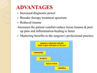
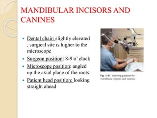
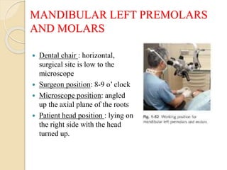
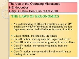
DENTAL OPERATING
MICROSCOPE
PRESENTED BY,
Dr. KANAGA PRIYAA
VELLINGIRI
CONTENTS
 INTRODUCTION
 DOM
 MICROSCOPE PARTS
 ADVANTAGES
 DISADVANTAGES
 ERGONOMICS WORKING POSITION
 USES OF MICROSCOPE
 CONCLUSION
 REFERENCES
INTRODUCTION
DENTAL OPERATING MICROSCOPE
 In 1999, Gary Carr, introduced an OM that had Galilean
optics and that was ergonomically configured for dentistry,
with several advantages that allowed for easy use of the scope
for nearly all endodontic and restorative procedures.
 This OM had a magnification changer that allowed for:
- 5 discrete magnifications (magnification 3.5–30),
- a stable mounting on either the wall or ceiling,
- angled binoculars allowing for sit-down dentistry,
configured with adapters for an assistant’s scope and video or
35-mm cameras
Galilean optics. Parallel optics
enables the observer to focus
at infinity, relieving
eyestrain.
LIMITS OF HUMAN VISION
RUBBER DAM & MIRROR PLACEMENT
(A) Inadequate level of magnification and mirror position. (B) Adequate
magnification
to position mirror. (C) Adequate mirror position. Notice the flex of the mirror staff.
(D)
MICROSCOPE PARTS
 Eyepieces
 Binoculars
 Magnification changer
 Focusing knob
 Objective lens
 Beam splitter
 External monitor
 Picture & video adapters
 Digital picture camera
 Video camera
EYEPIECES
 3 types – depending on quality and
optical aberration correction
properties:
 Huygens(H),the most simple and
cheap
 Wide field (WF),with good vision in
all the field, edges included
 Plössl (PL),the most sophisticated
and high quality with good
correction of all optical aberrations.
 Available with 6.3,10,12.5,16,20
magnification powers & adjustable
diopter setting & rubber cups.
Occular differ in magnification,but
basically they all have a diopter
scale and rubber cups.users wearing
spectacles can adjust then or
introduce their own eye data into
the diopter scale,so they work at the
microscope without glasses
BINOCULARS
 Function – to project an intermediate image into the
focal plane of the eyepieces-set at the inter pupillar
distance.
 Separation of the light beams is what producers the
stereoscopic effect that allows depth perception.
Schematic of the
stereoscopic microscope’s
operation .after the light
reaches the surgical field ,it
is reflected back through
the objective lens ,through
the magnification changer
lenses,through the
binoculars and then exists
to the eye as two separate
beams of light
 Inclined binoculars are adjustable for positions up to and
sometimes beyond 180degress.
 Other ergonomic tools are the C code beam splitter and
the Carr extender. These bring the binoculars away from
the microscope and closer to the surgeon
(a)The carr extender
Comparison of use of (a) flat beam splitter ,with a
more forward operator’s back position,(b)C code
beam splitter that allows a straight back
 Other lateral adjustments may be made with the
Mechanical Optical Rotating Assembly (MORA)on the
Pico Zeiss microscope.
This mechanical optical rotating
assembly allows a 25 degree tilting
of the microscope body with
respect to the binoculars ,to
accommodate the surgeon in the
area of working
MAGNIFICATION CHANGER
 Located in the microscope body , the changer holds the
lenses that magnify the image in three or five steps
manually .
OPERATING MICROSCOPE
MAGNIFICATION RANGES AND THEIR
USES
FOCUSING KNOB
 The manual focusing knob changes the distance between the
microscope lens and the surgical field . Motorized focusing is
controlled by the inner ring and moves the objective lens closer
to or away from the surgical field.
Knobs for manual fine
focus control(yellow arrow)
&manual magnification
changer (red arrow)
(a)Inner ring ,(b) handle controls
for both fine motorized focus and
magnification
OBJECTIVE LENS
 The focal length of the objective lens determines the distance
between the lens and the surgical field.
 The closer the objective lens to the surgical field ,the higher
the final magnification at each step and the smaller the
diameter of the surgical field will be – but also, the smaller the
space for passing instruments and the greater likelihood of the
objective lens being splashed.
 In contrast ,objective lenses with longer focal lengths have
smaller magnification at each step,but allow more room for
cords and instruments passing between the operating field and
the lens and reduced splashing possibility.
 A variety of objective lenses are available with focal
lengths ranging from 100 mm to 400 mm .
Microscope support is provided by two
systems :springs or electromagnetic
clutches.
BEAM SPLITTER
(a),(b) straight beam splitter
between the microscope body
and binoculars send the
surgical field image to
documentation accessories.
various percentage of light
can be sent to the
accessories.there are virtual
splitters that take only 3.5%of
the light
(a),(b)this 45 degree
inclined C splitter between
the microscope body and
binoculars send the
surgical field image to the
documentation accessories
Co-observation tube , digital picture
camera , video camera attached to
the beam splitter
EXTERNAL MONITOR OR CO-
OBSERVATION TUBE
 External monitor-Four handed dentistry
 Co-observation tube-six handed dentistry
PICTURE AND VIDEO ADAPTERS
Digital picture
camera
Video camera
New adapters allow
the use of high
resolution picture
and video cameras
making professional
documentation
ADVANTAGES
 Increased diagnostic power
 Broader therapy treatment spectrum
 Reduced trauma
-Increases the patient comfort-reduce tissue trauma & post
op pain and inflammation-healing is faster
 Marketing benefits to the surgeon’s professional practice
DISADVANTAGES
 Learning curve
 Workplace arrangement and seated posture
 Skills aquisition
 Assistants learning curve
 Longer sessions
 Expensive armamentarium
ERGONOMIC SURGICAL
WORKING POSITIONS
 SURGEON’S STOOL POSITION
DENTAL CHAIR POSITION
 Maxillary teeth in the range of operators fingers-
sufficient space for legs below &microscope above.
 If dental chair is too high-shoulder pain results because
there is no arm support , if it is too low , then back pain.
SURGEON’S POSITION
PATIENT’S HEAD AND BODY
POSITION
WORKING POSITION
MAXILLARY RIGHT PREMOLARS AND
MOLARS
 Dental chair: slightly elevated
, surgical site is low to the
microscope
 Surgeon position: 11-12 o’
clock
 Microscope position: angled
down the axial plane of the
roots
 Patient head position : facing
slightly to the left for
premolars & lying on his left
side for molars ; mandible
right lateral extrusion.
MAXILLARY INCISORS AND
CANINES
 Dental chair:45 degrees
elevated , surgical site is low to
the microscope
 Surgeon position: 11-12 o’
clock
 Microscope position: angled
down the axial plane of the
roots
 Patient head position: occlusal
plane 45 degree to the floor :
patient looking ahead.
MAXILLARY LEFT PREMOLARS
AND MOLARS
 Dental chair :slightly elevated,
surgical site is low to the
microscope
 Surgeon position: 11-12 o’
clock
 Microscope position: angled
down the axial plane of the
roots
 Patient head position: facing
slightly to the right for
premolars & lying on his right
side for molars ; mandible right
lateral extrusion.
MANDIBULAR RIGHT
PREMOLARS AND MOLARS
 Dental chair: slightly elevated,
surgical site is low to the
microscope
 Surgeon position: 8-9 o’ clock
 Microscope position: angled up
the axial plane of the roots
 Patient head position : facing
slightly to the left
MANDIBULAR INCISORS AND
CANINES
 Dental chair: slightly elevated
, surgical site is higher to the
microscope
 Surgeon position: 8-9 o’ clock
 Microscope position: angled
up the axial plane of the roots
 Patient head position: looking
straight ahead
MANDIBULAR LEFT PREMOLARS
AND MOLARS
 Dental chair : horizontal,
surgical site is low to the
microscope
 Surgeon position: 8-9 o’ clock
 Microscope position: angled
up the axial plane of the roots
 Patient head position : lying on
the right side with the head
turned up.
The Use of the Operating Microscope
inEndodontics
Gary B. Carr– Dent Clin N Am 2010
THE LAWS OF ERGONOMICS
 An understanding of efficient workflow using an OM
entails knowledge of the basics of ergonomic motion.
Ergonomic motion is divided into 5 classes of motion:
 Class I motion: moving only the fingers
 Class II motion: moving only the fingers and wrists
 Class III motion: movement originating from the elbow
 Class IV motion: movement originating from the
shoulder
 Class V motion: movement that involves twisting or
bending at the waist.
This unbalanced position ,with forward inclination from
the waist with diaphragm compression ,affects hips ,
shoulders and neck : the right hip advancement and
rotation ; left shoulder’s elevation & advancement ;
rotation & right shoulder depression ,backward and
posterior rotation ;improper positioning of elbow ,wrist
and fingers .executive muscles are working as stable
(A) Intermediary magnification of endodontic access on tooth No. 15 (note there is
no sign of canals). (B) Dentin smear resulted from ultrasonic instrumentation of
pulp
floor. (C) Groove produced after ultrasonic usage. (D) Mesiobuccal (MB) and
second MB
(A) Regular and retro mirror comparison. (B) Apical exploration after root
resection.
(C, D) Microsurgery technique. (E) Ultrasonic retro preparation. (F) Retro
preparation filled.
(G) Immediately postoperation. (H) Long-term recall.
(A) Before operation. (B) Ultrasonic root preparation with moderated bevel,
(C) Micromirror view of retropreparation, (D) Immediately postoperation. (E)
5-year recall. (F) 10-year recall.
(A) Immediately postoperation. (B) 48 hours postoperation. (C) 21 days
postoperation.Incision scar barely visible.
CONCLUSION
ARE YOU GOING TO BUY A
MICROSCOPE?
&
ARE YOU GOING TO PRACTICE
NEWLY UNDER THE DOM?
REFERENCES
 Endodontic microsurgery – Enrique M.Merino
 The Use of the Operating Microscope inEndodontics
Gary B. Carr– Dent Clin N Am 2010
 Micro‐endodontics: Aggrandizement of root canal treatment-Sameer
d jain1-International Dental Journal of student’s research| June‐Sep
2012| Volume 1| Issue 2
 Magnification and illumination in apical surgery-Richard
Rubinstein-Endodontic Topics 2005, 11, 56–77
 Use of the Microscope in Endodontics: Results of a Questionnaire-
Daniel D. Kersten, DDS, Pete Mines, DDS, and Mark Sweet, DDS-
JOE—Volume 34, Number 7, July 2008
 The Effect of the Dental Operating Microscope on the Outcome of
Nonsurgical Root Canal Treatment: A Retrospective Case-control
Study Navid Khalighinejad, DDS et al-J Endod 2017
 The microscope and endodontics Syngcuk Kim, DDS, MPhil, PhD,
MD(hon)a,*,Seungho Baek, DDS, PhDb-Dent Clin N Am 48 (2004)
11–18
 The impact of operating microscope on the outcome of endodontic
treatment performed by postgraduate students-monica monea,
associate professor, DMD, phd et al -European Scientific Journal
September 2015 edition vol.11, No.27
 Operating microscope in endodontics: A systematic review Carla
Cabral dos Santos Accioly Lins1et al -Open Journal of Stomatology,
2013, 3, 1-5
 The impact of loupes and microscopes on vision in endodontics-P.
Perrin, K. W. Neuhaus & A. Lussi-International Endodontic Journal,
47, 425–429, 2014
 The role of microendodontics in the treatment of difficult cases such as
C-shaped orifice of mandibular second molar with 5 canals-Harry Huiz
Peeters-- Padjadjaran Journal of Dentistry 2008;20(3):186-89.
Dental operating microscope

Dental operating microscope

  • 1.
  • 2.
    CONTENTS  INTRODUCTION  DOM MICROSCOPE PARTS  ADVANTAGES  DISADVANTAGES  ERGONOMICS WORKING POSITION  USES OF MICROSCOPE  CONCLUSION  REFERENCES
  • 3.
  • 4.
    DENTAL OPERATING MICROSCOPE In 1999, Gary Carr, introduced an OM that had Galilean optics and that was ergonomically configured for dentistry, with several advantages that allowed for easy use of the scope for nearly all endodontic and restorative procedures.  This OM had a magnification changer that allowed for: - 5 discrete magnifications (magnification 3.5–30), - a stable mounting on either the wall or ceiling, - angled binoculars allowing for sit-down dentistry, configured with adapters for an assistant’s scope and video or 35-mm cameras
  • 5.
    Galilean optics. Paralleloptics enables the observer to focus at infinity, relieving eyestrain.
  • 6.
  • 9.
    RUBBER DAM &MIRROR PLACEMENT (A) Inadequate level of magnification and mirror position. (B) Adequate magnification to position mirror. (C) Adequate mirror position. Notice the flex of the mirror staff. (D)
  • 11.
    MICROSCOPE PARTS  Eyepieces Binoculars  Magnification changer  Focusing knob  Objective lens  Beam splitter  External monitor  Picture & video adapters  Digital picture camera  Video camera
  • 12.
    EYEPIECES  3 types– depending on quality and optical aberration correction properties:  Huygens(H),the most simple and cheap  Wide field (WF),with good vision in all the field, edges included  Plössl (PL),the most sophisticated and high quality with good correction of all optical aberrations.  Available with 6.3,10,12.5,16,20 magnification powers & adjustable diopter setting & rubber cups. Occular differ in magnification,but basically they all have a diopter scale and rubber cups.users wearing spectacles can adjust then or introduce their own eye data into the diopter scale,so they work at the microscope without glasses
  • 13.
    BINOCULARS  Function –to project an intermediate image into the focal plane of the eyepieces-set at the inter pupillar distance.  Separation of the light beams is what producers the stereoscopic effect that allows depth perception.
  • 14.
    Schematic of the stereoscopicmicroscope’s operation .after the light reaches the surgical field ,it is reflected back through the objective lens ,through the magnification changer lenses,through the binoculars and then exists to the eye as two separate beams of light
  • 15.
     Inclined binocularsare adjustable for positions up to and sometimes beyond 180degress.
  • 16.
     Other ergonomictools are the C code beam splitter and the Carr extender. These bring the binoculars away from the microscope and closer to the surgeon (a)The carr extender
  • 17.
    Comparison of useof (a) flat beam splitter ,with a more forward operator’s back position,(b)C code beam splitter that allows a straight back
  • 18.
     Other lateraladjustments may be made with the Mechanical Optical Rotating Assembly (MORA)on the Pico Zeiss microscope. This mechanical optical rotating assembly allows a 25 degree tilting of the microscope body with respect to the binoculars ,to accommodate the surgeon in the area of working
  • 19.
    MAGNIFICATION CHANGER  Locatedin the microscope body , the changer holds the lenses that magnify the image in three or five steps manually .
  • 20.
  • 21.
    FOCUSING KNOB  Themanual focusing knob changes the distance between the microscope lens and the surgical field . Motorized focusing is controlled by the inner ring and moves the objective lens closer to or away from the surgical field. Knobs for manual fine focus control(yellow arrow) &manual magnification changer (red arrow) (a)Inner ring ,(b) handle controls for both fine motorized focus and magnification
  • 22.
    OBJECTIVE LENS  Thefocal length of the objective lens determines the distance between the lens and the surgical field.  The closer the objective lens to the surgical field ,the higher the final magnification at each step and the smaller the diameter of the surgical field will be – but also, the smaller the space for passing instruments and the greater likelihood of the objective lens being splashed.  In contrast ,objective lenses with longer focal lengths have smaller magnification at each step,but allow more room for cords and instruments passing between the operating field and the lens and reduced splashing possibility.
  • 23.
     A varietyof objective lenses are available with focal lengths ranging from 100 mm to 400 mm .
  • 24.
    Microscope support isprovided by two systems :springs or electromagnetic clutches.
  • 25.
    BEAM SPLITTER (a),(b) straightbeam splitter between the microscope body and binoculars send the surgical field image to documentation accessories. various percentage of light can be sent to the accessories.there are virtual splitters that take only 3.5%of the light (a),(b)this 45 degree inclined C splitter between the microscope body and binoculars send the surgical field image to the documentation accessories
  • 26.
    Co-observation tube ,digital picture camera , video camera attached to the beam splitter
  • 27.
    EXTERNAL MONITOR ORCO- OBSERVATION TUBE  External monitor-Four handed dentistry  Co-observation tube-six handed dentistry PICTURE AND VIDEO ADAPTERS
  • 28.
    Digital picture camera Video camera Newadapters allow the use of high resolution picture and video cameras making professional documentation
  • 29.
    ADVANTAGES  Increased diagnosticpower  Broader therapy treatment spectrum  Reduced trauma -Increases the patient comfort-reduce tissue trauma & post op pain and inflammation-healing is faster  Marketing benefits to the surgeon’s professional practice
  • 30.
    DISADVANTAGES  Learning curve Workplace arrangement and seated posture  Skills aquisition  Assistants learning curve  Longer sessions  Expensive armamentarium
  • 31.
    ERGONOMIC SURGICAL WORKING POSITIONS SURGEON’S STOOL POSITION
  • 32.
    DENTAL CHAIR POSITION Maxillary teeth in the range of operators fingers- sufficient space for legs below &microscope above.  If dental chair is too high-shoulder pain results because there is no arm support , if it is too low , then back pain. SURGEON’S POSITION
  • 33.
    PATIENT’S HEAD ANDBODY POSITION
  • 34.
    WORKING POSITION MAXILLARY RIGHTPREMOLARS AND MOLARS  Dental chair: slightly elevated , surgical site is low to the microscope  Surgeon position: 11-12 o’ clock  Microscope position: angled down the axial plane of the roots  Patient head position : facing slightly to the left for premolars & lying on his left side for molars ; mandible right lateral extrusion.
  • 35.
    MAXILLARY INCISORS AND CANINES Dental chair:45 degrees elevated , surgical site is low to the microscope  Surgeon position: 11-12 o’ clock  Microscope position: angled down the axial plane of the roots  Patient head position: occlusal plane 45 degree to the floor : patient looking ahead.
  • 36.
    MAXILLARY LEFT PREMOLARS ANDMOLARS  Dental chair :slightly elevated, surgical site is low to the microscope  Surgeon position: 11-12 o’ clock  Microscope position: angled down the axial plane of the roots  Patient head position: facing slightly to the right for premolars & lying on his right side for molars ; mandible right lateral extrusion.
  • 37.
    MANDIBULAR RIGHT PREMOLARS ANDMOLARS  Dental chair: slightly elevated, surgical site is low to the microscope  Surgeon position: 8-9 o’ clock  Microscope position: angled up the axial plane of the roots  Patient head position : facing slightly to the left
  • 38.
    MANDIBULAR INCISORS AND CANINES Dental chair: slightly elevated , surgical site is higher to the microscope  Surgeon position: 8-9 o’ clock  Microscope position: angled up the axial plane of the roots  Patient head position: looking straight ahead
  • 39.
    MANDIBULAR LEFT PREMOLARS ANDMOLARS  Dental chair : horizontal, surgical site is low to the microscope  Surgeon position: 8-9 o’ clock  Microscope position: angled up the axial plane of the roots  Patient head position : lying on the right side with the head turned up.
  • 40.
    The Use ofthe Operating Microscope inEndodontics Gary B. Carr– Dent Clin N Am 2010 THE LAWS OF ERGONOMICS  An understanding of efficient workflow using an OM entails knowledge of the basics of ergonomic motion. Ergonomic motion is divided into 5 classes of motion:  Class I motion: moving only the fingers  Class II motion: moving only the fingers and wrists  Class III motion: movement originating from the elbow  Class IV motion: movement originating from the shoulder  Class V motion: movement that involves twisting or bending at the waist.
  • 43.
    This unbalanced position,with forward inclination from the waist with diaphragm compression ,affects hips , shoulders and neck : the right hip advancement and rotation ; left shoulder’s elevation & advancement ; rotation & right shoulder depression ,backward and posterior rotation ;improper positioning of elbow ,wrist and fingers .executive muscles are working as stable
  • 48.
    (A) Intermediary magnificationof endodontic access on tooth No. 15 (note there is no sign of canals). (B) Dentin smear resulted from ultrasonic instrumentation of pulp floor. (C) Groove produced after ultrasonic usage. (D) Mesiobuccal (MB) and second MB
  • 56.
    (A) Regular andretro mirror comparison. (B) Apical exploration after root resection. (C, D) Microsurgery technique. (E) Ultrasonic retro preparation. (F) Retro preparation filled. (G) Immediately postoperation. (H) Long-term recall.
  • 57.
    (A) Before operation.(B) Ultrasonic root preparation with moderated bevel, (C) Micromirror view of retropreparation, (D) Immediately postoperation. (E) 5-year recall. (F) 10-year recall.
  • 58.
    (A) Immediately postoperation.(B) 48 hours postoperation. (C) 21 days postoperation.Incision scar barely visible.
  • 59.
    CONCLUSION ARE YOU GOINGTO BUY A MICROSCOPE? & ARE YOU GOING TO PRACTICE NEWLY UNDER THE DOM?
  • 60.
    REFERENCES  Endodontic microsurgery– Enrique M.Merino  The Use of the Operating Microscope inEndodontics Gary B. Carr– Dent Clin N Am 2010  Micro‐endodontics: Aggrandizement of root canal treatment-Sameer d jain1-International Dental Journal of student’s research| June‐Sep 2012| Volume 1| Issue 2  Magnification and illumination in apical surgery-Richard Rubinstein-Endodontic Topics 2005, 11, 56–77  Use of the Microscope in Endodontics: Results of a Questionnaire- Daniel D. Kersten, DDS, Pete Mines, DDS, and Mark Sweet, DDS- JOE—Volume 34, Number 7, July 2008
  • 61.
     The Effectof the Dental Operating Microscope on the Outcome of Nonsurgical Root Canal Treatment: A Retrospective Case-control Study Navid Khalighinejad, DDS et al-J Endod 2017  The microscope and endodontics Syngcuk Kim, DDS, MPhil, PhD, MD(hon)a,*,Seungho Baek, DDS, PhDb-Dent Clin N Am 48 (2004) 11–18  The impact of operating microscope on the outcome of endodontic treatment performed by postgraduate students-monica monea, associate professor, DMD, phd et al -European Scientific Journal September 2015 edition vol.11, No.27  Operating microscope in endodontics: A systematic review Carla Cabral dos Santos Accioly Lins1et al -Open Journal of Stomatology, 2013, 3, 1-5  The impact of loupes and microscopes on vision in endodontics-P. Perrin, K. W. Neuhaus & A. Lussi-International Endodontic Journal, 47, 425–429, 2014  The role of microendodontics in the treatment of difficult cases such as C-shaped orifice of mandibular second molar with 5 canals-Harry Huiz Peeters-- Padjadjaran Journal of Dentistry 2008;20(3):186-89.