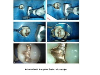
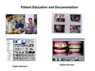
DENTAL OPERATING MICROSCOPE
Dr.Kishore Kumar Majety
Introduction
History of the Dental Operating Microscope
The Magnification Continuum
Loupes
Operating Microscope
Advantages of the Operating Microscope
Anatomy of the Operating Microscope & How it works
magnification
illumination
Accessories
Documentation
Choosing the right one
Optimum configurations
Operating Positions
Dental chair position
Surgeon’s position
Patients position
Jaw manipulation and access for posterior teeth
Assistants position
Specific Operating Positions
USES of Operating Microscope
Diagnosis
Restorative Dentistry
Endodontics
conventional endodontics
surgical endodontics
Use of magnification in Dental technology
Microscopic photography
Patient education and Documentation
Practice enhancement
Conclusion
References
• 350 yrs ago Robert Hooke looked into a compound microscope and
saw an image he called a cell
• In the later part of the 20th century, physicians recognised the
practicality and benefits of treating damaged and diseased tissues
under higher magnification
Robert hooke’s microsccope
“ YOU CANNOT TREAT WHAT YOU CANNOT SEE ”
- Dr Garry Carr
MAGNIFYING LOUPES
Are a vast improvement over unaided vision
Offer magnification 2.5x to 6x
But have major short comings
People who wear eyeglasses: the frame is glazed with
protective, plano power lenses (0 D). Prescription lenses
can easily be integrated by your own eye care provider.
Ease of use: relaxed treatment with an ergonomically
correct body posture and optimum working distance
1) Lightweight: titanium frame and soft bridge for
maximum comfort.
(2) Simple adjustment: height and tilt are easy to set
with a Torx key.
(3) PD: easy to set for each eye using the folding
bridge.
1) Lightweight: the headband system evenly distributes the minimal weight of the Prism Loupes
over the entire head area.
(2) Comfortable: the headband can be adapted to practically any head. Adjust the width using this button.
(3) A neat solution: the removable textile pads are washable.
(4) Height and depth: turn the button, adjust, finished.
(5) Eye contact with the patient: the Prism Loupes can be easily swung out of your field of view with one
simple movement.
(6) Tilt angle: fast and precise setting with a single adjustment.
Shortcomings of Magnifying loupes
• Limited range of magnification 2.5x to 6x
• Individualised to the user
• Limited depth of field , limited feld of view when compared to an operating microscope
• Weight related fatigue
• Less than optimal ergonomics
• Lack of real time guidance while operating
Advantages with the Operating Microscope
• Mulitple magnifications 2.5x to 16x or greater
• Multiuser capability
• Accomplish co observation
• Case documentation
• Facilitate to have a digital database
• Improved ergonomics
Types of Operating microscopes available
Floor mounted
Wall mounted
Ceiling mounted
Wall mounted
The Anatomy of the Operating Microscope and
How it Works
EYEPIECE
BODY
HANDLE
GRIPS
OBJECTIVE LENS
MAGNIFICATION
CHANGERS
FINE FOCUSING
MAGNIFICATION
Determined by the
Me- power of the eyepiece ,
Ft - focal length of the binoculars,
Mc - magnification changer factor,
Fo- focal length of the objective lens ,
Total magnification
Mt = Ft / Fo x Me x Mc
Eyepieces
• play an important role in magnification
• generally available in powers of x6.3, x10, x16, x20
• have an adjustable diopter settings from - 5 to + 5
• diopter settings also adjust for the refractive power
• with a reticule field can aid for alignment during
videotaping and photography
Binoculars
• hold the eyepieces in position
• project an intermediate image into the focal plane
of the eyepieces
• interpupillary distance is set by adjusting the
two binocular tubes
• come in different focal lengths
• available with Straight , inclined or inclinable tubes
Magnification changer
located on the side of the body of the microscope
controlled either manually or by a foot control ( power zoom changer )
Magnification range with Operating Microscope
Multiple steps of magnification
Low power 2.5X to 4X
viewing of multiple teeth in the field
diagnosis
periodontal surgery
gross reduction of tooth structure during full coverage tooth preparation
orientation of the surgical field
alignment of surgical tips
Medium power 6.4X to 16X
diagnosis
surgical procedures
retro preparations
Highest powers > 16X
for spot checks during treatment
digital photography
Focusing knob
located on the side of the body of the microscope
To focus the scope onto the field
Parfocalisation
The process of setting the operator specific focus for the entire range
of magnifications
To parfocal a microscope,
a flat object is placed under the microscope and focused at the highest
magnification
set when the object appears clear
Objective lens
The focal length of the objective lens determines the operating distance
between the lens and the surgical field
Available focal lengths 100 to 400 mm
a 175mm lens focuses at about 7 inches
a 200mm 8 inches
a 400mm 16 inches
A 200mm objective lens is recommended
Objective lens
ILLUMINATION
Path of light from a light source
Light source systems
Two light source systems commonly available
1. Xenon halogen bulb used in a fan cooled system
2. Quartz halogen bulb, found in fiberoptic light system
Beam splitter
Supply light to an accessory such as a camera or an auxillary observation tube
Can be inserted in the pathway of light as it returns to the operators eyes
Accessories
COOBSERVATION TUBE
PHOTOGRAPHIC
ADAPTER
CINE ADAPTER
PISTOL GRIPS
EYEPIECE WITH A
RETICULE FIELD
A TV monitor or preferably an LCD screen
Optimum configurations
12.5X eyepieces
125mm straight or inclinable binoculars
200 to 250m objective lens
A five step manual magnification changer or a power zoom magnification changer
This package would allow the clinician
to work comfortably about 8 inches from the patient
in the magnification range of 3X to 26X
the power zoom would allow a smooth zoom with an 8:1 ratio
easy magnification and focus adjustments
Excellent optics
Mechanical stability
test for stability : gently tap the end of the arm of the microscope when it is fully extended
In a good microscope, superior suspension and balance mechanisms prevent the arm from
moving or bouncing in response to position adjustments
Maneuverability
The microscope should be light for almost effortless maneuverability
Modularity/ adaptability
Operating positions
The most appropriate operating position for a given surgeon is a combination of
Patient’s head position
Dental chair position
Microscope position
Assistant observation devices
Patient’s position
View of a patient readied for surgery
A travel pillow is an excellent support for
the neck and head
Keeping the head turned mote than slightly for a
Prolonged period may cause torquing of the neck muscles.
This position should be avoided
For the patients and surgeon’s comfort,the patient lies on the side during posterior surgery
Jaw manipulation and access for Posterior teeth
Lateral extrusion gains another1/2 to
1-inch of space for maxillary
molar surgery
Mandibular protrusion gives greater
access for mandibular molar surgery
Dental chair position
That ensures maximum comfort
Manipulating the chair’s height and back position, allows sufficient space between
the legs and space between the scope and the operating field
The chair is adjusted twice
1. To create the necessary clearence between the objective lens and the patient’s
mouth
2. Once the surgeon has assumed an ergonomically correct position and has
determined the corresponding correct
position, minor adjustments can be made in the patient’s chair position
The patient is positioned,
slightly below the microscope for maxillary surgery
slightly above it for mandibular surgery
Surgeon’s position
Use an adjustable stool
Thighs parallel to the floor
Arms should be relaxed and comfortable at sides
Specially designed stools are available
Assistant’s position
A well designed microsurgery may need three assistants
FIRST ASSISTANT
responsible for suctioning, usually seated
SECOND ASSISTANT
Passes instruments, positioned next to the surgeon’s dominant site
if a front delivery system is used, positioned across the surgeon
THIRD ASSISTANT
incharge of the video and photographic functions
Specific operator positions
operating positions for a RIGHT HANDED SURGEON
Maxillary Left Posterior position
* surgeon positioned to the right and to the rear of the patient
* occlusal plane perpendicular to the floor
* patient faces slightly to the right for premolar area and turns on to the
right side for molar area
* scope angled down the plane of the roots
* dental chair position low in relation to the microscope
Maxillary Anterior position
* surgeon positioned to the right and to the rear of the
patient
* occlusal plane perpendicular to the floor
* patient looking straight ahead
* scope angled down the plane of the roots
* dental chair position low
Maxillary Right Posterior position
* surgeon positioned to the right and to the rear of the
patient
* occlusal plane perpendicular to the floor
* patient faces slightly to the left for premolar area and
turns on to the left side for molar area
* scope angled down the plane of the roots
* dental chair position low in relation to the microscope
Mandibular Left Posterior position
•surgeon positioned to the left and to the side of the
patient
* occlusal plane parallel to the floor
* patient looking straight ahead or slightly to the right
* scope angled up the plane of the roots
* dental chair position low in relation to the microscope
* First assistant stands or sits depending on comfort
* instruments on the bracket tray behind the patient
Mandibular Anterior position
* surgeon positioned to the right and toward the front of
the patient
* occlusal plane parallel to the floor
* patient looking straight ahead
* scope angled up the plane of the roots
* dental chair position low in relation to the microscope
* Second assistant moves to the left of the chair and makes
room for the surgeon
•surgeon positioned to the right and to the side of the
patient
* occlusal plane parallel to the floor
* patient looking straight ahead or slightly to the left
* scope angled up the plane of the roots
* dental chair position low in relation to the microscope
Mandibular Right Posterior position
Uses of Operating Miscroscope
Uses in Diagnosis
1. Diagnosis of early enamel and dentine cracks
at a range of 14X – 18X
Type I:Little or no risk of underlying pathology
include
A. Craze lines that are usually linear or vertical and do not widen or become more pronounced as they
extend from gingival to occlusal
B. Vertical cracks not associated with restorations and without enamel stain penetration
C. Cracks that follow natural anatomic grroves
D. Cracks with superficial environmental stain penetration
E. Cracks that result from polymerisation of composite resin
2. Cracked tooth syndrome
3. Marginal leakage of restorations
4. Soft tissue evaluation
Uses in Restorative dentistry
Pulpal involvement
Coronal preparation
Impression quality
examining the impression surface for imperfections, distortions and marginal inadequacies at the time
of impression making eliminates laboratory guess work
Evaluating the restoration under surface
Restoration delivery and polish
Bonded restorations
Use of magnification in Dental technology
Six key areas of the fabrication of restorations where magnification is essential
1. Inspection of the impression
the impression of tooth structure that extends apical to the preparation or just beyond the margin should
be clearly visible to the unaided eye
it should then be inspected for clarity under a minimum of 12X
2. Trimming and marking of the die and marking the terminal edgeof the die at 20X
3. Waxing of the margin
4. Fitting of the initial casting
5. Final fitting of the restoration
6. Final polishing of the restoration
Achieved with the global 6- step microscope
Patient Education and Documentation
Digital data base
Digital data base
In Endodontics
1. Conventional / Non-surgical endodontics
2. Surgical endodontics
Non surgical root canal treatment
Rubber dam application aids in the vision
CORONAL ACCESS
Should be large
The coronal part of the cavity can be flared for better vision
Removing the roof of the pulp chamber is easier to achieve the microscope
Use of ultrasonics is also suggested
Once deroofing is done inspect the floor of the pulp chamber under high magnificatiom
Orientation should be done at 6X , then increase the magnification to 12X to enhance what is seen
at the lower magnification
Magnification upto 26X can be used to confirm the openings
PREPARATION OF THE ROOTCANAL
With the microscope the shape the preparation in the coronal part of each root canal can be
examined and progress monitored easily.
Prepare the root canal
In straight root canal it is possible to see the full length of the root canal
OBTURATION OF THE ROOT CANAL
The distribution of the sealer coronal to any curve can be verified at 16X or 26X.
After completion of the obturation to remove excess guttapercha
1. Coronal access
in obliterated pulp chambers
2. Locating orifices
DG 16
Micro openers
Ulltrasonics in pecking motion
3. Locating missed canals
available literature indicatec that the dtection of MB2 improved when an operating microscope is used
4. Negotiation of calcifed canals
5. Preparation of Post space
6. Removal of silver points
7. Retrevial of separated instrument
8. Removal of Post during re treatment
9. Repair of perforations
10. Diagnosis of incomplete or complete radicular cracks
Endodontic microsurgery
Triad of Endodontic microsurgery
Conventional surgery vs Microsurgery
Procedure
Identification of the apex difficult precise
Osteotomy large small
Bevel angle acute 45 degree shallow < 10 degree
Isthmus identification impossible easy
Retro preparation approximate coaxial to root
Retrofilling imprecise precise
1. Identification of the apex in the intact buccal plate
at 10X to 16X
2. Osteotomy
3. Resected root surface
stained with methylene blue
examined carefully with a micro explorer under 12X to 25X
identifies causes of treatment failure
4. Isthmus identification
5. Retroprepararion
6. Retrofilling
Conventional suturing vs microsuturing
Maintainence of the microscope
Cover the scope with plastic covers
Disinfect the parts handled
Clean the eyepiece and the objective lens with lens cleaner
CONCLUSION
OPERATING MICROSCOPE IS AN ASSET WHICH WILL CHANGE THE WAY YOU
TREAT
References
Pathways of Pulp
Cohen & Burnns
Microscopes in endodontics
Dental Clinics of North America , Vol. 41 no.3 July 1997
Color atlas of Microsurgery in endodontics
Sungcuk kim with Gabriele Pecora and Richard A.Rubinstein
The Dental Operating Microscope and its slow acceptance
Journal of Endodontics vol.28 no.3 March 2003
Journal of Esthetic and Restorative Dentistry vol.15, no.7, November 2003
Personal video monitor as an accessory to dental operating microscopes
Quintessence international 20044; 35: 151-154
The benefit of operating microscope for access cavity preparation by UG students
Journal of Endodontics vol.30, no.12, 2004
Effect of magnification in locating the MB2 canal in maxillary molars
Journal of Endodontics vol.28, no.4, 2002
Short term observation of the results of endodontic surgery with the use of surgical operating microscope and
Super EBA as root filling material
Journal of Endodontics vol.25, no.1, Jan 1999
Frequency of MB2 in maxillary molars as detected by an operating microscope – a clinical study
Journal of Endodontics vol.26, no.11, Nov 2000
Operating microscope improves negotiation of MB2 in maxillary molars
Journal of Endodontics vol.27, no.11, Nov 2001
Use of Microscope in Endodontics – a report based on a questionnaire
Journal of Endodontics vol.25, no.11, Nov 1999
Use of DOM in endodontic surgery
Oral Path , Oral Med, Oral Radiol, Endo1993; 75: 95 - 105
THANK YOU

dental operating microscope.ppt

  • 1.
  • 2.
    Introduction History of theDental Operating Microscope The Magnification Continuum Loupes Operating Microscope Advantages of the Operating Microscope Anatomy of the Operating Microscope & How it works magnification illumination Accessories Documentation Choosing the right one Optimum configurations
  • 3.
    Operating Positions Dental chairposition Surgeon’s position Patients position Jaw manipulation and access for posterior teeth Assistants position Specific Operating Positions USES of Operating Microscope Diagnosis Restorative Dentistry Endodontics conventional endodontics surgical endodontics Use of magnification in Dental technology Microscopic photography Patient education and Documentation Practice enhancement
  • 4.
  • 5.
    • 350 yrsago Robert Hooke looked into a compound microscope and saw an image he called a cell • In the later part of the 20th century, physicians recognised the practicality and benefits of treating damaged and diseased tissues under higher magnification Robert hooke’s microsccope
  • 6.
    “ YOU CANNOTTREAT WHAT YOU CANNOT SEE ” - Dr Garry Carr
  • 8.
    MAGNIFYING LOUPES Are avast improvement over unaided vision Offer magnification 2.5x to 6x But have major short comings
  • 9.
    People who weareyeglasses: the frame is glazed with protective, plano power lenses (0 D). Prescription lenses can easily be integrated by your own eye care provider. Ease of use: relaxed treatment with an ergonomically correct body posture and optimum working distance 1) Lightweight: titanium frame and soft bridge for maximum comfort. (2) Simple adjustment: height and tilt are easy to set with a Torx key. (3) PD: easy to set for each eye using the folding bridge.
  • 10.
    1) Lightweight: theheadband system evenly distributes the minimal weight of the Prism Loupes over the entire head area. (2) Comfortable: the headband can be adapted to practically any head. Adjust the width using this button. (3) A neat solution: the removable textile pads are washable. (4) Height and depth: turn the button, adjust, finished. (5) Eye contact with the patient: the Prism Loupes can be easily swung out of your field of view with one simple movement. (6) Tilt angle: fast and precise setting with a single adjustment.
  • 11.
    Shortcomings of Magnifyingloupes • Limited range of magnification 2.5x to 6x • Individualised to the user • Limited depth of field , limited feld of view when compared to an operating microscope • Weight related fatigue
  • 12.
    • Less thanoptimal ergonomics • Lack of real time guidance while operating
  • 13.
    Advantages with theOperating Microscope • Mulitple magnifications 2.5x to 16x or greater • Multiuser capability • Accomplish co observation • Case documentation • Facilitate to have a digital database • Improved ergonomics
  • 14.
    Types of Operatingmicroscopes available Floor mounted Wall mounted Ceiling mounted Wall mounted
  • 15.
    The Anatomy ofthe Operating Microscope and How it Works EYEPIECE BODY HANDLE GRIPS OBJECTIVE LENS MAGNIFICATION CHANGERS FINE FOCUSING
  • 16.
    MAGNIFICATION Determined by the Me-power of the eyepiece , Ft - focal length of the binoculars, Mc - magnification changer factor, Fo- focal length of the objective lens , Total magnification Mt = Ft / Fo x Me x Mc
  • 17.
    Eyepieces • play animportant role in magnification • generally available in powers of x6.3, x10, x16, x20 • have an adjustable diopter settings from - 5 to + 5 • diopter settings also adjust for the refractive power • with a reticule field can aid for alignment during videotaping and photography
  • 18.
    Binoculars • hold theeyepieces in position • project an intermediate image into the focal plane of the eyepieces • interpupillary distance is set by adjusting the two binocular tubes • come in different focal lengths • available with Straight , inclined or inclinable tubes
  • 19.
    Magnification changer located onthe side of the body of the microscope controlled either manually or by a foot control ( power zoom changer )
  • 20.
    Magnification range withOperating Microscope Multiple steps of magnification Low power 2.5X to 4X viewing of multiple teeth in the field diagnosis periodontal surgery gross reduction of tooth structure during full coverage tooth preparation orientation of the surgical field alignment of surgical tips Medium power 6.4X to 16X diagnosis surgical procedures retro preparations Highest powers > 16X for spot checks during treatment digital photography
  • 21.
    Focusing knob located onthe side of the body of the microscope To focus the scope onto the field
  • 22.
    Parfocalisation The process ofsetting the operator specific focus for the entire range of magnifications To parfocal a microscope, a flat object is placed under the microscope and focused at the highest magnification set when the object appears clear
  • 23.
    Objective lens The focallength of the objective lens determines the operating distance between the lens and the surgical field Available focal lengths 100 to 400 mm a 175mm lens focuses at about 7 inches a 200mm 8 inches a 400mm 16 inches A 200mm objective lens is recommended Objective lens
  • 24.
  • 25.
    Path of lightfrom a light source
  • 26.
    Light source systems Twolight source systems commonly available 1. Xenon halogen bulb used in a fan cooled system 2. Quartz halogen bulb, found in fiberoptic light system
  • 27.
    Beam splitter Supply lightto an accessory such as a camera or an auxillary observation tube Can be inserted in the pathway of light as it returns to the operators eyes
  • 28.
  • 29.
    A TV monitoror preferably an LCD screen
  • 30.
    Optimum configurations 12.5X eyepieces 125mmstraight or inclinable binoculars 200 to 250m objective lens A five step manual magnification changer or a power zoom magnification changer This package would allow the clinician to work comfortably about 8 inches from the patient in the magnification range of 3X to 26X the power zoom would allow a smooth zoom with an 8:1 ratio easy magnification and focus adjustments
  • 31.
    Excellent optics Mechanical stability testfor stability : gently tap the end of the arm of the microscope when it is fully extended In a good microscope, superior suspension and balance mechanisms prevent the arm from moving or bouncing in response to position adjustments Maneuverability The microscope should be light for almost effortless maneuverability Modularity/ adaptability
  • 33.
    Operating positions The mostappropriate operating position for a given surgeon is a combination of Patient’s head position Dental chair position Microscope position Assistant observation devices
  • 34.
    Patient’s position View ofa patient readied for surgery A travel pillow is an excellent support for the neck and head Keeping the head turned mote than slightly for a Prolonged period may cause torquing of the neck muscles. This position should be avoided For the patients and surgeon’s comfort,the patient lies on the side during posterior surgery
  • 35.
    Jaw manipulation andaccess for Posterior teeth Lateral extrusion gains another1/2 to 1-inch of space for maxillary molar surgery Mandibular protrusion gives greater access for mandibular molar surgery
  • 36.
    Dental chair position Thatensures maximum comfort Manipulating the chair’s height and back position, allows sufficient space between the legs and space between the scope and the operating field The chair is adjusted twice 1. To create the necessary clearence between the objective lens and the patient’s mouth 2. Once the surgeon has assumed an ergonomically correct position and has determined the corresponding correct position, minor adjustments can be made in the patient’s chair position The patient is positioned, slightly below the microscope for maxillary surgery slightly above it for mandibular surgery
  • 38.
    Surgeon’s position Use anadjustable stool Thighs parallel to the floor Arms should be relaxed and comfortable at sides Specially designed stools are available
  • 40.
    Assistant’s position A welldesigned microsurgery may need three assistants FIRST ASSISTANT responsible for suctioning, usually seated SECOND ASSISTANT Passes instruments, positioned next to the surgeon’s dominant site if a front delivery system is used, positioned across the surgeon THIRD ASSISTANT incharge of the video and photographic functions
  • 41.
    Specific operator positions operatingpositions for a RIGHT HANDED SURGEON Maxillary Left Posterior position * surgeon positioned to the right and to the rear of the patient * occlusal plane perpendicular to the floor * patient faces slightly to the right for premolar area and turns on to the right side for molar area * scope angled down the plane of the roots * dental chair position low in relation to the microscope
  • 42.
    Maxillary Anterior position *surgeon positioned to the right and to the rear of the patient * occlusal plane perpendicular to the floor * patient looking straight ahead * scope angled down the plane of the roots * dental chair position low
  • 43.
    Maxillary Right Posteriorposition * surgeon positioned to the right and to the rear of the patient * occlusal plane perpendicular to the floor * patient faces slightly to the left for premolar area and turns on to the left side for molar area * scope angled down the plane of the roots * dental chair position low in relation to the microscope
  • 44.
    Mandibular Left Posteriorposition •surgeon positioned to the left and to the side of the patient * occlusal plane parallel to the floor * patient looking straight ahead or slightly to the right * scope angled up the plane of the roots * dental chair position low in relation to the microscope * First assistant stands or sits depending on comfort * instruments on the bracket tray behind the patient
  • 45.
    Mandibular Anterior position *surgeon positioned to the right and toward the front of the patient * occlusal plane parallel to the floor * patient looking straight ahead * scope angled up the plane of the roots * dental chair position low in relation to the microscope * Second assistant moves to the left of the chair and makes room for the surgeon
  • 46.
    •surgeon positioned tothe right and to the side of the patient * occlusal plane parallel to the floor * patient looking straight ahead or slightly to the left * scope angled up the plane of the roots * dental chair position low in relation to the microscope Mandibular Right Posterior position
  • 47.
    Uses of OperatingMiscroscope
  • 48.
    Uses in Diagnosis 1.Diagnosis of early enamel and dentine cracks at a range of 14X – 18X Type I:Little or no risk of underlying pathology include A. Craze lines that are usually linear or vertical and do not widen or become more pronounced as they extend from gingival to occlusal B. Vertical cracks not associated with restorations and without enamel stain penetration C. Cracks that follow natural anatomic grroves
  • 49.
    D. Cracks withsuperficial environmental stain penetration E. Cracks that result from polymerisation of composite resin
  • 50.
    2. Cracked toothsyndrome 3. Marginal leakage of restorations 4. Soft tissue evaluation
  • 51.
    Uses in Restorativedentistry Pulpal involvement Coronal preparation Impression quality examining the impression surface for imperfections, distortions and marginal inadequacies at the time of impression making eliminates laboratory guess work Evaluating the restoration under surface Restoration delivery and polish Bonded restorations
  • 53.
    Use of magnificationin Dental technology Six key areas of the fabrication of restorations where magnification is essential 1. Inspection of the impression the impression of tooth structure that extends apical to the preparation or just beyond the margin should be clearly visible to the unaided eye it should then be inspected for clarity under a minimum of 12X 2. Trimming and marking of the die and marking the terminal edgeof the die at 20X
  • 54.
    3. Waxing ofthe margin 4. Fitting of the initial casting 5. Final fitting of the restoration
  • 55.
    6. Final polishingof the restoration
  • 58.
    Achieved with theglobal 6- step microscope
  • 59.
    Patient Education andDocumentation Digital data base Digital data base
  • 60.
    In Endodontics 1. Conventional/ Non-surgical endodontics 2. Surgical endodontics
  • 61.
    Non surgical rootcanal treatment Rubber dam application aids in the vision CORONAL ACCESS Should be large The coronal part of the cavity can be flared for better vision Removing the roof of the pulp chamber is easier to achieve the microscope Use of ultrasonics is also suggested Once deroofing is done inspect the floor of the pulp chamber under high magnificatiom Orientation should be done at 6X , then increase the magnification to 12X to enhance what is seen at the lower magnification Magnification upto 26X can be used to confirm the openings
  • 62.
    PREPARATION OF THEROOTCANAL With the microscope the shape the preparation in the coronal part of each root canal can be examined and progress monitored easily. Prepare the root canal In straight root canal it is possible to see the full length of the root canal OBTURATION OF THE ROOT CANAL The distribution of the sealer coronal to any curve can be verified at 16X or 26X. After completion of the obturation to remove excess guttapercha
  • 63.
    1. Coronal access inobliterated pulp chambers 2. Locating orifices DG 16 Micro openers Ulltrasonics in pecking motion
  • 64.
    3. Locating missedcanals available literature indicatec that the dtection of MB2 improved when an operating microscope is used 4. Negotiation of calcifed canals 5. Preparation of Post space 6. Removal of silver points 7. Retrevial of separated instrument
  • 65.
    8. Removal ofPost during re treatment 9. Repair of perforations 10. Diagnosis of incomplete or complete radicular cracks
  • 66.
    Endodontic microsurgery Triad ofEndodontic microsurgery
  • 68.
    Conventional surgery vsMicrosurgery Procedure Identification of the apex difficult precise Osteotomy large small Bevel angle acute 45 degree shallow < 10 degree Isthmus identification impossible easy Retro preparation approximate coaxial to root Retrofilling imprecise precise
  • 69.
    1. Identification ofthe apex in the intact buccal plate at 10X to 16X 2. Osteotomy 3. Resected root surface stained with methylene blue examined carefully with a micro explorer under 12X to 25X identifies causes of treatment failure
  • 70.
  • 71.
  • 72.
  • 73.
    Maintainence of themicroscope Cover the scope with plastic covers Disinfect the parts handled Clean the eyepiece and the objective lens with lens cleaner
  • 74.
    CONCLUSION OPERATING MICROSCOPE ISAN ASSET WHICH WILL CHANGE THE WAY YOU TREAT
  • 75.
    References Pathways of Pulp Cohen& Burnns Microscopes in endodontics Dental Clinics of North America , Vol. 41 no.3 July 1997 Color atlas of Microsurgery in endodontics Sungcuk kim with Gabriele Pecora and Richard A.Rubinstein The Dental Operating Microscope and its slow acceptance Journal of Endodontics vol.28 no.3 March 2003 Journal of Esthetic and Restorative Dentistry vol.15, no.7, November 2003 Personal video monitor as an accessory to dental operating microscopes Quintessence international 20044; 35: 151-154 The benefit of operating microscope for access cavity preparation by UG students Journal of Endodontics vol.30, no.12, 2004 Effect of magnification in locating the MB2 canal in maxillary molars Journal of Endodontics vol.28, no.4, 2002 Short term observation of the results of endodontic surgery with the use of surgical operating microscope and Super EBA as root filling material Journal of Endodontics vol.25, no.1, Jan 1999 Frequency of MB2 in maxillary molars as detected by an operating microscope – a clinical study Journal of Endodontics vol.26, no.11, Nov 2000 Operating microscope improves negotiation of MB2 in maxillary molars Journal of Endodontics vol.27, no.11, Nov 2001
  • 76.
    Use of Microscopein Endodontics – a report based on a questionnaire Journal of Endodontics vol.25, no.11, Nov 1999 Use of DOM in endodontic surgery Oral Path , Oral Med, Oral Radiol, Endo1993; 75: 95 - 105
  • 77.