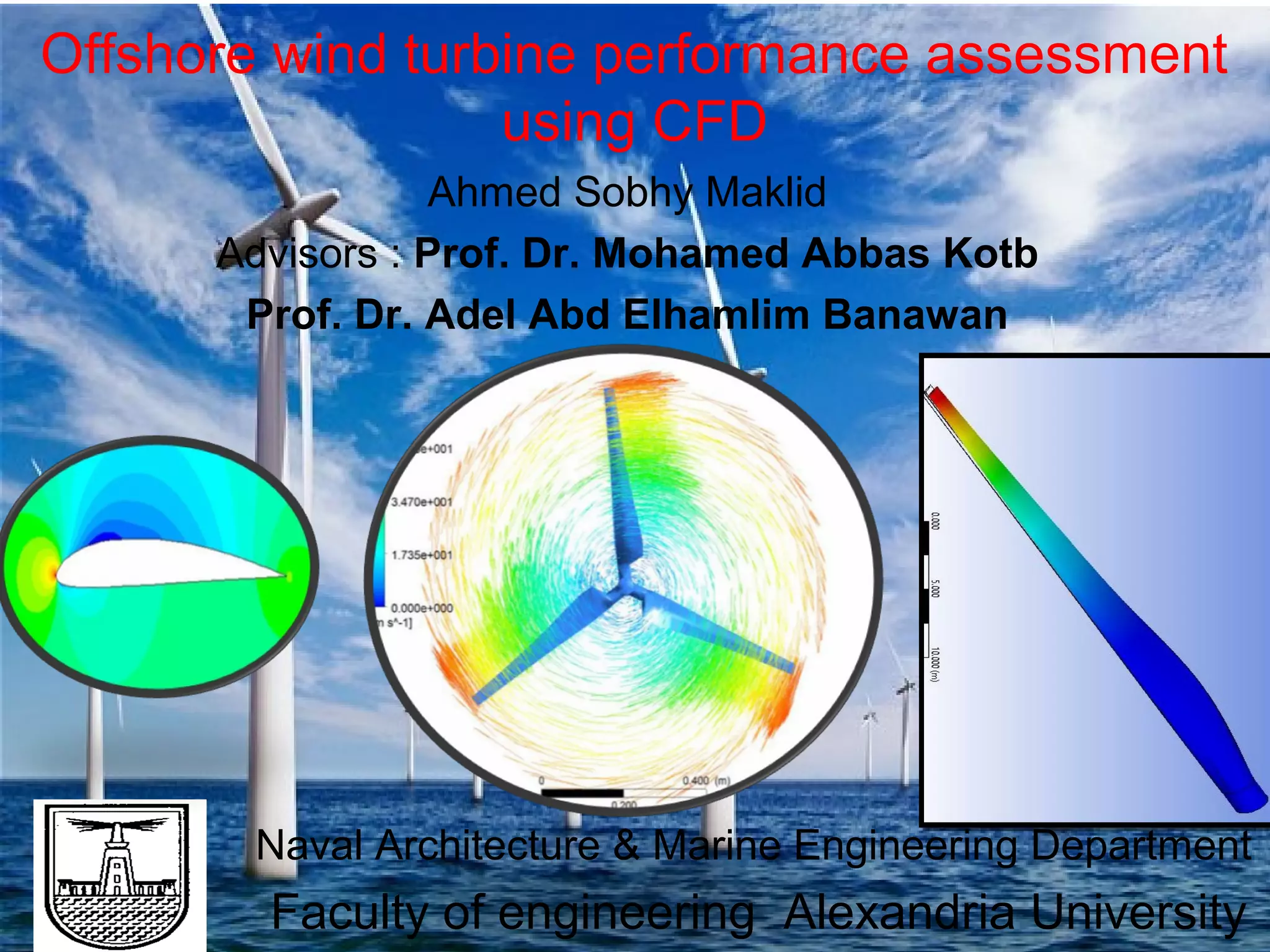
This document outlines a presentation on assessing offshore wind turbine performance using computational fluid dynamics (CFD). It discusses conducting various CFD case studies including 2D airfoil simulations, a full 3D turbine simulation, and a fluid-structure interaction study of a turbine blade and foundation. Verification and validation studies were performed and the results were compared to experimental data. The conclusions were that CFD is a useful tool for wind turbine design when conducted with verification and validation, and that future work could include more advanced simulations such as transient fluid-structure interaction and floating offshore foundations.


![Presentation Outline
Title Slide: «backstory»
Outline
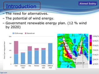
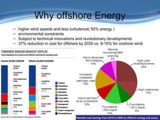
Introduction/Motivation
Background
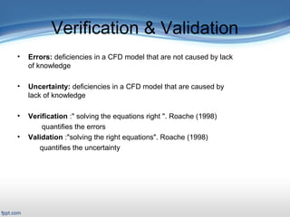
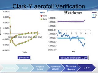
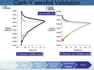
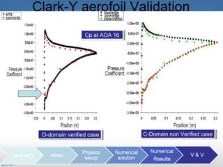
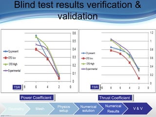
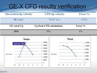
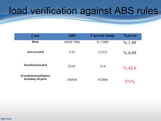
Verification & Validation
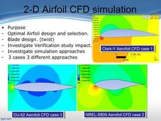
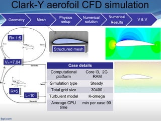
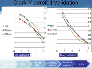
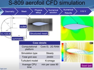
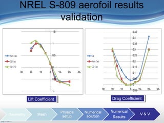
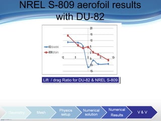
2-D case study
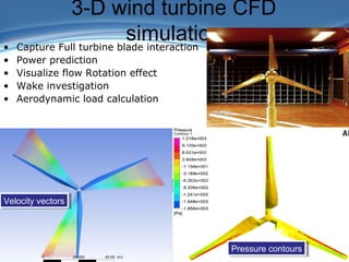
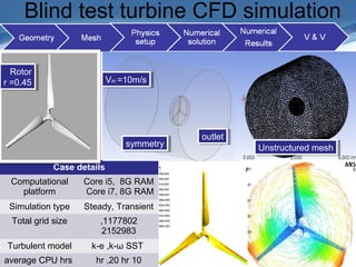
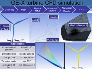
Full turbine case study
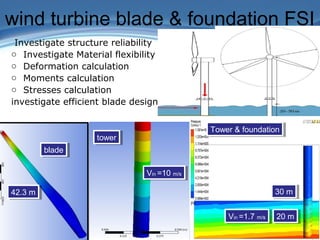
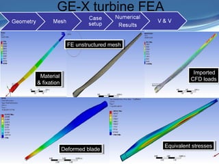
FSI case study
Related work
Conclusions and Future work
References
[1]. The New and Renewable Energy Authority, Cairo, Egypt NREA.
http://www.nrea.gov.eg/english1.html
[2]. www.windpowermonthly.com/article/1317185/onshore-wind-cheaper-coal-nuclear-gas.
[3]. “Offshore Wind Power Summary Report” (TINA) www.lowcarboninnovation.co.uk.
[4]. Zahedi A, “Current status and future prospects of the wind energy”, Conference on Power &
Energy, IEEE
[5].‘Introduction to Computational Fluid Dynamics (CFD)” University of Iowa,
http://css.engineering.uiowa.edu/~fluids.
[6] Dan M. Somers, “Design and Experimental Results for the S809 Airfoil”, National Renewable
Energy Laboratory, NREL.
[7] Hamid Rahimi, “Computational Modeling of Wind Turbines in Open FOAM” presentation on the
Center for Wind Energy Research Institute of Physics, University of Oldenburg, Germany.
[8] Blind test calculations of the performance and wake development for a model wind turbine”,
Norwegian University of Science and Technology NTNU,
[9]. https://confluence.cornell.edu/pages/viewpage.action?pageId=262012971.
[47] H K Versteeg and W Malalasekera, “An Introduction to Computational Fluid Dynamics THE
FINITE VOLUME METHOD” Second edition © Pearson Education Limited 1995, 2007.](https://image.slidesharecdn.com/1sttrial-161121132532/85/Offshore-wind-turbine-performance-assessment-using-CFD-28-320.jpg)


![Sikkema brian[1]](https://cdn.slidesharecdn.com/ss_thumbnails/sikkemabrian1-140905055927-phpapp02-thumbnail.jpg?width=640&height=640&fit=bounds)


