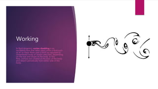
The document outlines the development and analysis of bladeless wind turbines, which utilize vortex shedding to generate electricity with significantly lower maintenance costs compared to conventional turbines. It details the design components, advantages such as independent operation from wind direction, and applications in low wind speed areas. The analysis includes stress and airflow studies, indicating the turbine's effectiveness and potential for cost-effective energy production.

![Material Properties
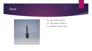
Carbon Fibre (Std. UD) [Base]
Young’s Modulus 135 GPa
Poisson’s Ratio 0.3
Ult. Tensile Strength 1500 MPa
Ult. Comp Strength 1200 MPa
Density 1.6 g/cc
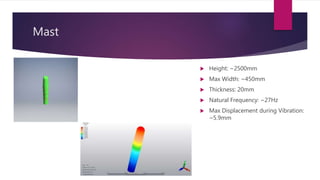
Fibreglass (E Glass Fabric) [Mast]
Young’s Modulus 25 GPa
Poisson’s Ratio 0.2
Ult. Tensile Strength 440 MPa
Ult. Comp Strength 425 MPa
Density 1.9 g/cc](https://image.slidesharecdn.com/bladelesswindturbine3rdreview-190128134216/85/Bladeless-Wind-Turbine-Vortex-Bladeless-12-320.jpg)