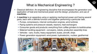
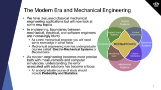
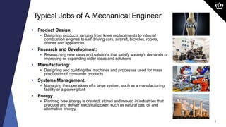
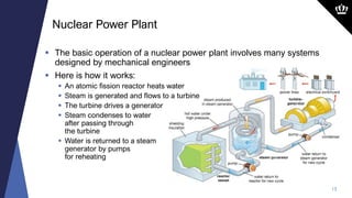
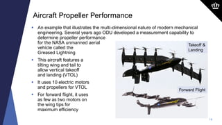
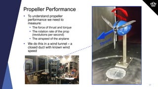
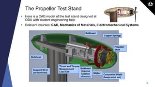
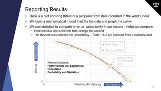
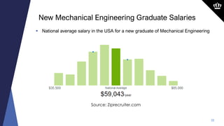
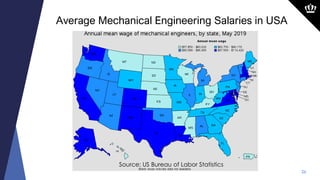
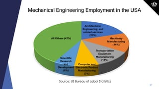
An Introduction to
Mechanical Engineering
Dr. Drew Landman
Professor and Associate Chair
Department of Mechanical
and
Aerospace Engineering
2
 Classical definition: An engineering discipline that encompasses the generation and
application of heat and mechanical power and the design, production, and use of
machines.
 A machine is an apparatus using or applying mechanical power and having several
parts, each with a definite function and together performing a particular task.
 Pumps, compressors, internal combustion engines, wind turbines
 Piping systems and pressure vessels, reactors, heat exchangers
 Consumer goods and products: everything from coffee grinders to toothbrushes
 Material handling equipment - conveyers, robots, production assembly lines
 Vehicles - cars, trucks, heavy equipment, buses, aircraft, ships
 Power generation equipment: wind power, hydroelectric, nuclear, geothermal
What is Mechanical Engineering ?
3
 We have discussed classical mechanical
engineering applications but will now look at
some new topics
 In engineering, boundaries between
mechanical, electrical, and software engineers
are increasingly blurry
 As a new mechanical engineer you will need
some knowledge in other fields
 Mechanical engineering now has undergraduate
courses called Electro-Mechanical Systems or
Mechatronics
 As modern engineering becomes more precise
both with measurements and computer
simulations, understanding the error
associated with solutions has become a focus
 An undergraduate course of study should
include Probability and Statistics
The Modern Era and Mechanical Engineering
4
 Product Design:
 Designing products ranging from knee replacements to internal
combustion engines to self driving cars, aircraft, bicycles, robots,
drones and appliances
 Research and Development:
 Researching new ideas and solutions that satisfy society’s demands or
improving or expanding older ideas and solutions
 Manufacturing:
 Designing and building the machines and processes used for mass
production of consumer products
 Systems Management:
 Managing the operations of a large system, such as a manufacturing
facility or a power plant
 Energy
 Planning how energy is created, stored and moved in industries that
produce and deliver electrical power, such as natural gas, oil and
alternative energy
Typical Jobs of A Mechanical Engineer
Wind Power Example
 In the next slides we will examine the role mechanical engineers
play in the design, manufacture and management of systems for
energy generation using wind
 Text in BOLD identifies relevant coursework from the
undergraduate curriculum
6
 A wind turbine extracts energy from the movement of air in the atmosphere
 Here is the basic concept of operation:
Mechanical Engineering of the Wind Turbine
Turbine
Blades
Generator
Transformer
Distribution
Home &
Business
Wind Turbine
7
 At a given location, wind velocity
over the earth increases with
height near the surface
 The change in velocity is due to
skin friction from the air being in
contact with the surface of the
earth
 At the ground, the wind velocity is
zero
 This layer where velocity changes
is called the boundary layer and
you will learn about it in Fluid
Mechanics
 This is the reason wind turbines
are mounted high above the earth
 They generate more electricity in
higher winds
Wind Turbine Aerodynamics
8
 The rotor blades spin a main shaft at low speed that is supported by bearings
 The low-speed shaft drives gears in a gear box which in turn drives the
generator; all have bearings
 The blades can be rotated on their
axes to adjust pitch and are supported
by their own bearings
 The whole assembly can be turned
into the wind via the yaw bearing
 All of these devices have
to be analyzed and designed
to withstand the given loads
over a long lifetime
 The design of these
components requires
courses like Dynamics,
Mechanics of Materials,
and Mechanical Design
Wind Turbine Machine Element Design
9
 To understand the loads on the structure we first need predictions for the forces
generated by the airflow over the blades
 The wind and blade rotation cause forces of Lift and Drag which you can learn
about in Fluid Mechanics and Aerodynamics coursework
Blade Aerodynamics
A Section of a Blade
10
 If we know what loads are applied to the blade we can now investigate which
materials are best to resist the loads
 Coursework in Materials Science and Mechanics of Materials will help us here
 Computer knowledge is essential in modern design; here is an image from a blade
that was designed using a Computer Aided Drafting program then analyzed using
a Finite Element Method, both courses in the undergraduate curriculum at ODU
 The image shows the deflection of the blade under wind loads
Blade Structure
11
 Now that the blade is designed, its time to
manufacture it
 The mechanical engineer will design a blade mold
that serves as the outer form
 Layers of composite fabric and resin will make up the
structure and be laid into the mold to cure
 Expertise here comes from knowledge of Composite
Materials
Composite Blade Manufacturing
Nuclear Power Example
 In the next slides we will examine the role mechanical engineers
play in the design, and management of systems for energy
generation using nuclear power
 Text in BOLD identifies relevant coursework from the
undergraduate curriculum
13
 The basic operation of a nuclear power plant involves many systems
designed by mechanical engineers
 Here is how it works:
 An atomic fission reactor heats water
 Steam is generated and flows to a turbine
 The turbine drives a generator
 Steam condenses to water
after passing through
the turbine
 Water is returned to a steam
generator by pumps
for reheating
Nuclear Power Plant
14
 The theory behind the thermal cycle water undergoes is a topic in two
courses in Thermodynamics
 The course Heat Transfer discusses the design of
heat exchangers such as the one
used to transfer heat from high
pressure water lines to steam in
the steam generator vessel
 Fluid Mechanics will cover
the sizing of pumps
 The pump shown at the right
features staged impellers to
increase pressure
Nuclear Power Plant
Propeller Performance
Measurement Example
 In the next slides we will examine the role mechanical engineers
play in the design, manufacture and use of instruments for
aerodynamic measurements on propellers
 Text in BOLD identifies relevant coursework from the
undergraduate curriculum
16
 An example that illustrates the multi-dimensional nature of modern mechanical
engineering. Several years ago ODU developed a measurement capability to
determine propeller performance
for the NASA unmanned aerial
vehicle called the
Greased Lightning
 This aircraft features a
tilting wing and tail to
allow vertical takeoff
and landing (VTOL)
 It uses 10 electric motors
and propellers for VTOL
 For forward flight, it uses
as few as two motors on
the wing tips for
maximum efficiency
Aircraft Propeller Performance
Forward Flight
Takeoff &
Landing
17
 To understand propeller
performance we need to
measure:
 The force of thrust and torque
 The rotation rate of the prop
(revolutions per second)
 The airspeed of the airplane
 We do this in a wind tunnel – a
closed duct with known wind
speed
Propeller Performance
18
 Here is a CAD model of the test stand designed at
ODU with student engineering help
 Relevant courses: CAD, Mechanics of Materials, Electromechanical Systems
The Propeller Test Stand
Thrust and Torque
Measurement
Load Cell
Composite Shield
(keeps wind out)
Copper Springs
Bulkhead
Support Strut
(streamlined)
Bulkhead
Motor
Bulkhead
(thermal
isolation
of motor)
Propeller
Shaft
19
 The load cell is an electro-mechanical sensor – a transducer
 Loads (Thrust and Torque) are sensed by small beams that deflect
 Relevant courses here are Mechanics of Materials and Finite Element Methods
The Thrust-Torque Load Cell Design
Beam sensitive to Thrust
Beams sensitive to Torque
Deflection is Exaggerated
Beams sensitive to Torque
Beam sensitive to Thrust
Computer model - torque and thrust load
Picture of finished transducer
20
 How do we design an instrument to measure force and torque ?
 One popular method is to use strain gages with mechanical elements like beams
 A strain gage is a piece of thin film with a very
thin wire arranged in a long serpentine shape called a grid
 The strain gage is bonded to a metal surface
 As the metal is under load, the gage wire length changes and so does the resistance
 Relevant courses here are Mechanics of Materials, Electromechanical Systems
Instrumentation Design: Electro-Mechanical Devices
Strain Gage
Electrical
Connection
Wire Grid
21
 Glue the strain gage to the beams that bend most with applied Thrust and Torque
 Connect them to a special circuit and now: Thrust is proportional to Voltage
Instrumentation Design: Electro-Mechanical Devices
Connection
Wire
Grid
Voltage
to
Computer
22
 To record the propeller torque and thrust, we use a computer
 Voltages are digitized in an Analog to Digital converter
 A program is written to display and file all the quantities measured
Using the Computer
Thrust and Torque
Displayed
Propeller Rotational Speed
Control for Propeller Speed
23
 Here is a plot showing thrust of a propeller from data recorded in the wind tunnel
 We build a mathematical model that fits the data and graph the curve
 We use statistics to compute error or uncertainty in our results – helps us compare
 Here the blue line is the first trial, orange the second
 The dashed lines indicate the uncertainty – Trials 1 & 2 are identical from a statistical test
Reporting Results
Thrust
Relative Air Velocity
0
0
Increasing
Increasing
Uncertainty
For Second
Trial
Relevant Courses:
Flight Vehicle Aerodynamics
Propulsion
Probability and Statistics
First Trial
Second Trial
Expectations
2019 ODU SAE Aero Design Team
25
 National average salary in the USA for a new graduate of Mechanical Engineering
New Mechanical Engineering Graduate Salaries
Source: Ziprecruiter.com
26
Average Mechanical Engineering Salaries in USA
Source: US Bureau of Labor Statistics
27
Mechanical Engineering Employment in the USA
Source: US Bureau of Labor Statistics
Resources at ODU
2019 ODU SAE Aero Design Team
https://www.odu.edu/mae

what-is-mechanical-engineering.pdf

  • 1.
    An Introduction to MechanicalEngineering Dr. Drew Landman Professor and Associate Chair Department of Mechanical and Aerospace Engineering
  • 2.
    2  Classical definition:An engineering discipline that encompasses the generation and application of heat and mechanical power and the design, production, and use of machines.  A machine is an apparatus using or applying mechanical power and having several parts, each with a definite function and together performing a particular task.  Pumps, compressors, internal combustion engines, wind turbines  Piping systems and pressure vessels, reactors, heat exchangers  Consumer goods and products: everything from coffee grinders to toothbrushes  Material handling equipment - conveyers, robots, production assembly lines  Vehicles - cars, trucks, heavy equipment, buses, aircraft, ships  Power generation equipment: wind power, hydroelectric, nuclear, geothermal What is Mechanical Engineering ?
  • 3.
    3  We havediscussed classical mechanical engineering applications but will now look at some new topics  In engineering, boundaries between mechanical, electrical, and software engineers are increasingly blurry  As a new mechanical engineer you will need some knowledge in other fields  Mechanical engineering now has undergraduate courses called Electro-Mechanical Systems or Mechatronics  As modern engineering becomes more precise both with measurements and computer simulations, understanding the error associated with solutions has become a focus  An undergraduate course of study should include Probability and Statistics The Modern Era and Mechanical Engineering
  • 4.
    4  Product Design: Designing products ranging from knee replacements to internal combustion engines to self driving cars, aircraft, bicycles, robots, drones and appliances  Research and Development:  Researching new ideas and solutions that satisfy society’s demands or improving or expanding older ideas and solutions  Manufacturing:  Designing and building the machines and processes used for mass production of consumer products  Systems Management:  Managing the operations of a large system, such as a manufacturing facility or a power plant  Energy  Planning how energy is created, stored and moved in industries that produce and deliver electrical power, such as natural gas, oil and alternative energy Typical Jobs of A Mechanical Engineer
  • 5.
    Wind Power Example In the next slides we will examine the role mechanical engineers play in the design, manufacture and management of systems for energy generation using wind  Text in BOLD identifies relevant coursework from the undergraduate curriculum
  • 6.
    6  A windturbine extracts energy from the movement of air in the atmosphere  Here is the basic concept of operation: Mechanical Engineering of the Wind Turbine Turbine Blades Generator Transformer Distribution Home & Business Wind Turbine
  • 7.
    7  At agiven location, wind velocity over the earth increases with height near the surface  The change in velocity is due to skin friction from the air being in contact with the surface of the earth  At the ground, the wind velocity is zero  This layer where velocity changes is called the boundary layer and you will learn about it in Fluid Mechanics  This is the reason wind turbines are mounted high above the earth  They generate more electricity in higher winds Wind Turbine Aerodynamics
  • 8.
    8  The rotorblades spin a main shaft at low speed that is supported by bearings  The low-speed shaft drives gears in a gear box which in turn drives the generator; all have bearings  The blades can be rotated on their axes to adjust pitch and are supported by their own bearings  The whole assembly can be turned into the wind via the yaw bearing  All of these devices have to be analyzed and designed to withstand the given loads over a long lifetime  The design of these components requires courses like Dynamics, Mechanics of Materials, and Mechanical Design Wind Turbine Machine Element Design
  • 9.
    9  To understandthe loads on the structure we first need predictions for the forces generated by the airflow over the blades  The wind and blade rotation cause forces of Lift and Drag which you can learn about in Fluid Mechanics and Aerodynamics coursework Blade Aerodynamics A Section of a Blade
  • 10.
    10  If weknow what loads are applied to the blade we can now investigate which materials are best to resist the loads  Coursework in Materials Science and Mechanics of Materials will help us here  Computer knowledge is essential in modern design; here is an image from a blade that was designed using a Computer Aided Drafting program then analyzed using a Finite Element Method, both courses in the undergraduate curriculum at ODU  The image shows the deflection of the blade under wind loads Blade Structure
  • 11.
    11  Now thatthe blade is designed, its time to manufacture it  The mechanical engineer will design a blade mold that serves as the outer form  Layers of composite fabric and resin will make up the structure and be laid into the mold to cure  Expertise here comes from knowledge of Composite Materials Composite Blade Manufacturing
  • 12.
    Nuclear Power Example In the next slides we will examine the role mechanical engineers play in the design, and management of systems for energy generation using nuclear power  Text in BOLD identifies relevant coursework from the undergraduate curriculum
  • 13.
    13  The basicoperation of a nuclear power plant involves many systems designed by mechanical engineers  Here is how it works:  An atomic fission reactor heats water  Steam is generated and flows to a turbine  The turbine drives a generator  Steam condenses to water after passing through the turbine  Water is returned to a steam generator by pumps for reheating Nuclear Power Plant
  • 14.
    14  The theorybehind the thermal cycle water undergoes is a topic in two courses in Thermodynamics  The course Heat Transfer discusses the design of heat exchangers such as the one used to transfer heat from high pressure water lines to steam in the steam generator vessel  Fluid Mechanics will cover the sizing of pumps  The pump shown at the right features staged impellers to increase pressure Nuclear Power Plant
  • 15.
    Propeller Performance Measurement Example In the next slides we will examine the role mechanical engineers play in the design, manufacture and use of instruments for aerodynamic measurements on propellers  Text in BOLD identifies relevant coursework from the undergraduate curriculum
  • 16.
    16  An examplethat illustrates the multi-dimensional nature of modern mechanical engineering. Several years ago ODU developed a measurement capability to determine propeller performance for the NASA unmanned aerial vehicle called the Greased Lightning  This aircraft features a tilting wing and tail to allow vertical takeoff and landing (VTOL)  It uses 10 electric motors and propellers for VTOL  For forward flight, it uses as few as two motors on the wing tips for maximum efficiency Aircraft Propeller Performance Forward Flight Takeoff & Landing
  • 17.
    17  To understandpropeller performance we need to measure:  The force of thrust and torque  The rotation rate of the prop (revolutions per second)  The airspeed of the airplane  We do this in a wind tunnel – a closed duct with known wind speed Propeller Performance
  • 18.
    18  Here isa CAD model of the test stand designed at ODU with student engineering help  Relevant courses: CAD, Mechanics of Materials, Electromechanical Systems The Propeller Test Stand Thrust and Torque Measurement Load Cell Composite Shield (keeps wind out) Copper Springs Bulkhead Support Strut (streamlined) Bulkhead Motor Bulkhead (thermal isolation of motor) Propeller Shaft
  • 19.
    19  The loadcell is an electro-mechanical sensor – a transducer  Loads (Thrust and Torque) are sensed by small beams that deflect  Relevant courses here are Mechanics of Materials and Finite Element Methods The Thrust-Torque Load Cell Design Beam sensitive to Thrust Beams sensitive to Torque Deflection is Exaggerated Beams sensitive to Torque Beam sensitive to Thrust Computer model - torque and thrust load Picture of finished transducer
  • 20.
    20  How dowe design an instrument to measure force and torque ?  One popular method is to use strain gages with mechanical elements like beams  A strain gage is a piece of thin film with a very thin wire arranged in a long serpentine shape called a grid  The strain gage is bonded to a metal surface  As the metal is under load, the gage wire length changes and so does the resistance  Relevant courses here are Mechanics of Materials, Electromechanical Systems Instrumentation Design: Electro-Mechanical Devices Strain Gage Electrical Connection Wire Grid
  • 21.
    21  Glue thestrain gage to the beams that bend most with applied Thrust and Torque  Connect them to a special circuit and now: Thrust is proportional to Voltage Instrumentation Design: Electro-Mechanical Devices Connection Wire Grid Voltage to Computer
  • 22.
    22  To recordthe propeller torque and thrust, we use a computer  Voltages are digitized in an Analog to Digital converter  A program is written to display and file all the quantities measured Using the Computer Thrust and Torque Displayed Propeller Rotational Speed Control for Propeller Speed
  • 23.
    23  Here isa plot showing thrust of a propeller from data recorded in the wind tunnel  We build a mathematical model that fits the data and graph the curve  We use statistics to compute error or uncertainty in our results – helps us compare  Here the blue line is the first trial, orange the second  The dashed lines indicate the uncertainty – Trials 1 & 2 are identical from a statistical test Reporting Results Thrust Relative Air Velocity 0 0 Increasing Increasing Uncertainty For Second Trial Relevant Courses: Flight Vehicle Aerodynamics Propulsion Probability and Statistics First Trial Second Trial
  • 24.
    Expectations 2019 ODU SAEAero Design Team
  • 25.
    25  National averagesalary in the USA for a new graduate of Mechanical Engineering New Mechanical Engineering Graduate Salaries Source: Ziprecruiter.com
  • 26.
    26 Average Mechanical EngineeringSalaries in USA Source: US Bureau of Labor Statistics
  • 27.
    27 Mechanical Engineering Employmentin the USA Source: US Bureau of Labor Statistics
  • 28.
    Resources at ODU 2019ODU SAE Aero Design Team https://www.odu.edu/mae