1. LESSON 1: Installing Electrical Protective Devices
Electrical protective devices detect anomalies in electric power systems to
prevent further damage. These ensure that the electrical service is continuous,
thus preventing accidents that can cause injury to people and damage to
equipment and buildings.
Types of Electrical Protective Devices
Fuse - is an overcurrent protection device that contains a circuit-operating
fusible member, which is heated and cut off by the overcurrent that passes
through it.
Circuit Breaker – is an automatic overcurrent device that trips on overloads
or shorts and is resettable. Its standard ampacity starts at 15A.
Earth Leakage Circuit Breaker
Push Reset-Only Thermal Circuit Breaker
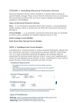
TOPIC 1: Panelboard and Circuit Breakers
A panelboard is a flush mounted or surface mounted distribution cabinet that
has overcurrent and short—circuit protection devices with The circuit home
run. If is used to distribute electricity throughout the building safely by
separating The electrical power feed into branch circuits and supplying each
circuit its own protective circuit breaker or fuse. A panelboard is also used To
protect branch circuits from overloads and short circuits.
2. Principles and Operation of Circuit Breakers
Circuit breakers operate through one or two principles, or a
combination of both.
1.Thermal operation depends on the additional heat brought out by
high current warming a bimetal strip, which bends to strip the
operating contacts.
3. 2.Magnetic operation happens when a coil carrying the current sets
up a magnetic field. This field attracts an iron part to trip the
breaker when the current becomes large enough.
Advantages of the Circuit Breaker over the Fuse:
1. The circuit breaker acts as both a switch and on overcurrent
protective device. When there is on overcurrent, the circuit
breaker trips, or cuts the current flow automatically. After
correcting the fault, it can be switched on already, unlike the
fuses that need to discarded and replaced after being busted.
2. A circuit breaker can protect and switch one to three lines
since it can be multiple poles and can be installed with1, 2, or
3 poles. A fuse can only protect a single electric line since it is
only a single-pole put into a single wire.
3. The circuit breaker position can be closed, tripped, or opened
right at the handle, which makes it easier to detect than the
fuse, which has the melted fusible element inside the fuse
casing.
4. A circuit breaker can also act as a circuit switch because it
can be manually tripped.
Important Ratings when Choosing Circuit Breakers
1. Rated voltage, Rated normal current - values used to designate it
and which is related to the operating conditions of the circuit
breaker.
2. Rated breaking capacity - expressed in MVA as the product of the
rated breaking current in kilo-amperes and the corresponding rated
voltage in kV.
3. Rated frequency — frequency of The electrical system in which
the circuit breaker is to be connected.
4.Rated short time current — effective value of current in which the
circuit breaker must carry for a stated time. This is required ’to
allow ’the flow of the fault current, which is cleared by another
circuit breaker.
4. Different Types of Circuit Breaker
Residual Current Circuit Breaker (RCCB)
The RCCB disconnects The circuit when there is a leak in the current
flow or There is no balance between the current and the phase
conductor, and thus ensuring protection from electric shock
due to direct contacts. If is generally used in series with on MCB.
Earth Leakage Circuit Breaker (ELCB)
The ELCB is found inside home electrical panels or distribution boards.
It functions similarly with on RCCB but as a voltage sensor device, and is
used for detecting electrical current leakage which normally occurs when
some parts of the installation are defective. Once electrical current
leakage has been detected, the ELCB trips the electricity supply for less
than a second to stop the magnitude of the current from reaching a
lethal level, and thus avoiding persons in contact to have serious injuries
caused by electric shock. It is commonly used in areas with high earth
impedance or high risk of electrical shock, and areas with high earth
Impedance usually have a local grounding (earth) rod and dry soil
conditions, which makes the current flow not strong enough to trip a
regular circuit breaker. An ELCB is more sensitive than a regular circuit
breaker, but not too sensitive to cause false alarms. The two 1ypes of
ELCB are Voltage Operated and Current Operated.
Difference Between RCCB and ELCB
RCCB ELCB
Residual Current Circuit Breaker Earth Leakage Circuit Breaker
Current -operated device Voltage Operated earth leakage device
Ensures full detection of current leakage, as
well 05 AC and DC current leakage
It can only detect current that flows back
through the main earth wire
Not connected to 1he earth wire, which
enables it to trip and withstand when both
phase and neutral currents are different
Functions according to the earth leakage
current They measure the voltage on the earth
conductor. A current leakage to earth is
identified when The voltage is not zero.
5. Miniature Circuit Breaker
The MCB switches off the electrical circuit automatically when if defects any
abnormal condition in The electrical networks such as overload or short circuit
to prevent fire or any electrical hazards. The MCB can be reset very quickly and
does not need any maintenance cost.
Molded Case Circuit Breaker
The MCCB is used when the load current surpasses the limit of an MCB. If is
used to protect against overload, short circuit faults, and to switch the circuits.
TOPIC 2: Safety Switch and Fuses
Safety Switch
Safety switches help prevent electrical accidents. Within 10 to 50 milliseconds,
they can interrupt excessive current by immediately switching off the power
due to dangerous electricity levels leaking to the earth through malfunctioning
switches, wiring, or appliances. Safety switches offer a hi h level of protection
to people from a possible electrical shock. Safety switches are a lot like circuit
breakers in a way that they are both located inside a control panel and that
they both out off electrical power when needed. However, circuit breakers
cannot prevent injuries to people involved since they only protect the wiring
from excess or overloading and do nothing during short-circuiting or electrical
leaks. On the other hand, safety switches protect people from harm by
monitoring any irregularities in the electrical system and immediately shutting
off the power if they did find any inconsistencies. Therefore it is highly
recommended to rely on both circuit breakers and safety switches.
6. Fusible safety switch
A Fusible Safety switch combines a safety switch with Fuses in a
single enclosure. The switch manually opens and Closes The
circuit, while the fuse protects against Overcurrent.
Non-Fusible Safety switch
A non-fusible safety switch has no associated fuses and no
circuit protection capability. It can only open and close a circuit
conveniently. When the circuit is opened, the load becomes
disconnected from the source of electrical power. Closing the
circuit reconnects the two components. External overcurrent
devices like circuit breakers or fuses must be provided to protect the circuit.
Types of Safety Switches
Switchboard of meter box units
These are installed on the main switchboard and protect selected or all circuits.
PowerPoint units
These are built in a single power point and protect a single circuit.
Portable units
These are commonly used with extension cords and portable power Tools.
Fuse
An electrical fuse is a type of current interrupting device that protects electrical
circuits by burning out the wire in the event of an excessive current flow so
that the circuit is discontinued already. Fuses are meant for single use only, so
it would need to be replaced when it works to cut off the power.
7. Classification of Fuses According to Manner of Operation
Single Element Fuse
When exposed to prolonged overload conditions, the restricted portions of the
fuse element heat To Their set melting point which allows its opening and Thus
interrupts current flow.
Dual Element Fuse
When exposed to prolonged overload conditions, the trigger spring breaks The
fusing alloy on releases the ”S’' connector.
Fuse Unique Performance Characteristics
1. Fuse Voltage Rating — the RMS (alternating) or direct voltage rating for
which fuse is designated
2. Fuse Current Rating - the desi noted RMS alternating or direct current
for which fuse will carry continuously under stated conditions.
3. Ampere Interrupting Capacity (AIC) Rating - cm are interrupting capacity
rating of a fuse (or CB) is the maximum short-circuit current which the
fuse will interrupt safely, i.e., without destroying itself. This is at rated
voltage and frequency.
Advantages of Fuse Over CIRCUIT Breaker
1. Fuses are more reliable and stable than circuit breakers because they
can remain in their position for years and perform their function when
activated.
2. Fuses cost lower than circuit breakers.
3. Circuit breakers have several moving parts, which require them to be
maintained and periodically tested to be in good condition.
LESSON 2: Testing Electrical Protective Devices
TOPIC 1: Testing of Circuit Breakers
Circuit Breaker Testing is utilized to test the operation of each switching
system and the programming of the entire tripping structure. It ensures the
safe and reliable performance of the device as a key link in the power supply
system. Circuit breakers perform three main tasks:
When closed, they must allow an efficient current flow.
8. When opened, they must provide effective insulation for each contact in
the breaker.
In case of malfunction, they must immediately and reliably disconnect
the fault current to protect all connected equipment.
Type Tests of Circuit Breaker
Type tests are performed to check the circuit breaker’s functionality and to
ensure its exact rated characteristics.
1. Mechanical Test – The circuit breaker is repeatedly opened and closed at
a proper speed to check if it performs its designated function without any
failure.
2. Thermal Test – This helps monitor the thermal behavior of the circuit
breakers. The temperature of the circuit breaker being tested steadily
rises due to the streaming of rated current that flows through its pole in
a rated condition. The increase in temperature for the rated current must
not go beyond 40° for current below 800A normal current, and 50° for
normal value current 800A and above.
3. Dielectric Test– This allows the checking of power frequency and the
capacity to withstand impulse voltage. Power frequency tests are
performed on new circuit breakers. The test voltage changes with a
circuit breaker rated voltage. In impulse tests, the breaker uses an
impulse voltage of particular. When the circuits are located outdoor, dry
and wet tests are performed.
4. Short -Circuit Test– Such tests are performed in short-circuit test
laboratories to subject the circuit breakers to sudden short-circuits. The
behavior of the breakers during switching in, contact breaking, and after
arc extinction is monitored by an oscillogram.
Inspecting Electrical Panels Through Thermal Imaging
Another way of inspecting circuit breakers is through the use of thermal
imaging.
9. TOPIC 2: Testing of Safety Switches with Fuses
Electrical protective devices are important to ensure the protection of devices,
facilities, and their inhabitants. As an electrical protective device, safety
switches must be tested periodically to check if they are performing well
according to their functions. Safety switches are tested manually.
A continuity test is performed to test if the fuse in the safety switch is blown.
Multimeters can be used to conduct this. Once configured, the multimeter can
measure the resistance of the fuse element. Resistance is measured in Ohms
'Ω'.
TOPIC 3: Testing of GFCI
GFCIs are relied on to provide a great deal of protection, which is why it is
important to test their functionality once every month. A GFCI can be tested
manually and through a multimeter tester to check for the voltage. Here are
the procedures for testing an installed GFCI.
LESSON 1: Defining Lightning Protection and
Grounding Systems
TOPIC 1: Types of Lightning Protection and Its Functions
10. Cotenery Wino Lightning C o n d o m '”'
• Thks sys c•m is similar ta a rrm&b cQgD vyhordiI•s a rftosh crf
sc«>dwcIsr3 ero yozatisnsd sl o diofoncs [rg'm 1ko 3 l r u s h
To ho |nrWâgsof¥ad fa rrynil IT
h
e lightning v.i4rro'nF cnming
D'treorzser EmissionLijghfning @onduotor
Cotonn rjr wire conductors ant plosed obov• flue ur9
to bs prolscfsd, They srs so*•r•ectsd
or•d dediyoted o<gr-thln@ Zystem3. the
cond to
of the mesh and
b d*p
Is requires the dafin”tion of insulation distances and
worrying out additional mechanical studies (resistor ce
for mosfs, qualifying ground pressure, rssisto nce
to wind nod weather scmdrtionp etc.).
Thissys&rr is parfsculorly used to protect open areas in
absence Of archltectur¢sl support or hozardcnv stcmuge.
L
P
Advantoges
Air-Te ination
ighwi«g
rofeotion
• Ecanomic
• Con be Intpgrotad Into the
building structure without
• Con only protect smaller
• Mechanical withstand comtroint
a! the mcrsfs
• Lsssers the ef/vcts on
oloctromognetic radiation within
the proloctcd structure and rhc
sp eod of Ightnlnq cure u r
several down conductors
conduzrhng structures and
gFound
• In6fQ ||Qfion iâ intñ cola and
• Complcxi ry of 1hO8truCtUfO doos
not t onslste ',vr|I to the
aesthetics
C<•nduosor
• Thi6 8yglam u8e8 On ionizo tion device iO a rfi(icially
generate an early upword leader occurring
bafore tha other natural upward Ieodsr . This is la
establish a designated impact point ot the
• The protect on rodlus g
pro ion, the *o imum volue being
iig hfning conducfor'5 Triggering odvOnoevotue(A
h i ht d th
{Legal III, height =60 ma1ars).
• It functions to protect zsnes sp rOO overs wider
eo sir+ce the oo ptura ol a lightning
foster compared to fhe use of a lightning rod. This
ensures fhe protection of large structured.
dependeon the
ffh
0 meters
Advantages
elac†romojprua-tic rocJi<¥0ion w?thi n
Jhe prodecfucJ s†o oture or-JcJ the
ground
P'rovidos op*sn zen•+ p•c.rgctIOn
• Prot<•c†c- save•oI bui Idings psing
• Profc<te a strL•ctu<o or•d its
9sJrroundi ng @-¥'1v'ir•@•nm TEst th.e
- Provides o p e n z e n e p ro zec tion
- C o m be inIe grot eel rnto be
I Lailc3i ng struc tu re wrthocxg
' r
UJ
Disaévan†oges
• to n as a threat in ho nailing
a r eo s ther¥a IiHir>g equips-nen† is
as.ed
P-x i v
L”
of
t rmn slo Iw well to the
bo 2 mofors and o b o e
Mechanical withs+a rid c o n t r a int
of the m e t s
14. So&fy Praooutlon
1.Before Slorting one sword,obtain necesco work permits frem the conoerne<t
epwsentative desi 1 d for the area.
2.Prapore all required equipmen1and tools to be uced tar the work.
5.Activltles must be conducted according to rhis procedure.
e. All worLi g c om Meal ba bfiafad a d ramiudod about aof tty ord oI1bo6io SOf8ty rBquiL0¥hBrIB
tO ensura a sofa ond heal-Fig srLflew.
5. The site supervisor fore'mon a nd assigneessafety engineer must continuousfy mo itor and
inspect the area. unsafe proc*ices while performing the work activities shall be co erected
immediately=a avo‹dany delay or halting of the work.
d.Moiotsin good hgusakeep ng s› all timesduring work. Keep the eite clean snd tidy.
7.Ali worL oct ••ties must be monitored by the safely engineer to help and prDseCf oil
assigned warfare against exposure to soFety hozo de. Personal Protective Equipment (PPE)
musf be supplied o nd WOrn of‘ oII him@s by oIt warders.
15. TOPIC 2: Procedures in Installing Grounding Systems
The purpose of earthing or grounding is to connect electrical conductors to the
earth. The earthing system transfers the current or electrical fields generated
around the structures or electrical devices to the ground. Aside from that,
earthing serves the following purposes:
Protects personnel against electrical hazards like electric shock and
electrocution
Safeguards electrical devices, appliances, power tools, machinery, and
etc. from current leakage
Lightning Arresters protect the structures, installations, and the entire
electrical system from damage from lightning.
Prevents fire in the electrical systems
Avoids interference with communication circuits
Installing Ground Rods
It is important to have ground rods in the electrical system because they create
an efficient route leading to the outside of the building for stray electricity that
occurs during a short or other malfunction. Installation of grounding rods
must be conducted with proper planning and care to minimize the threat of
electrical fire and injury.