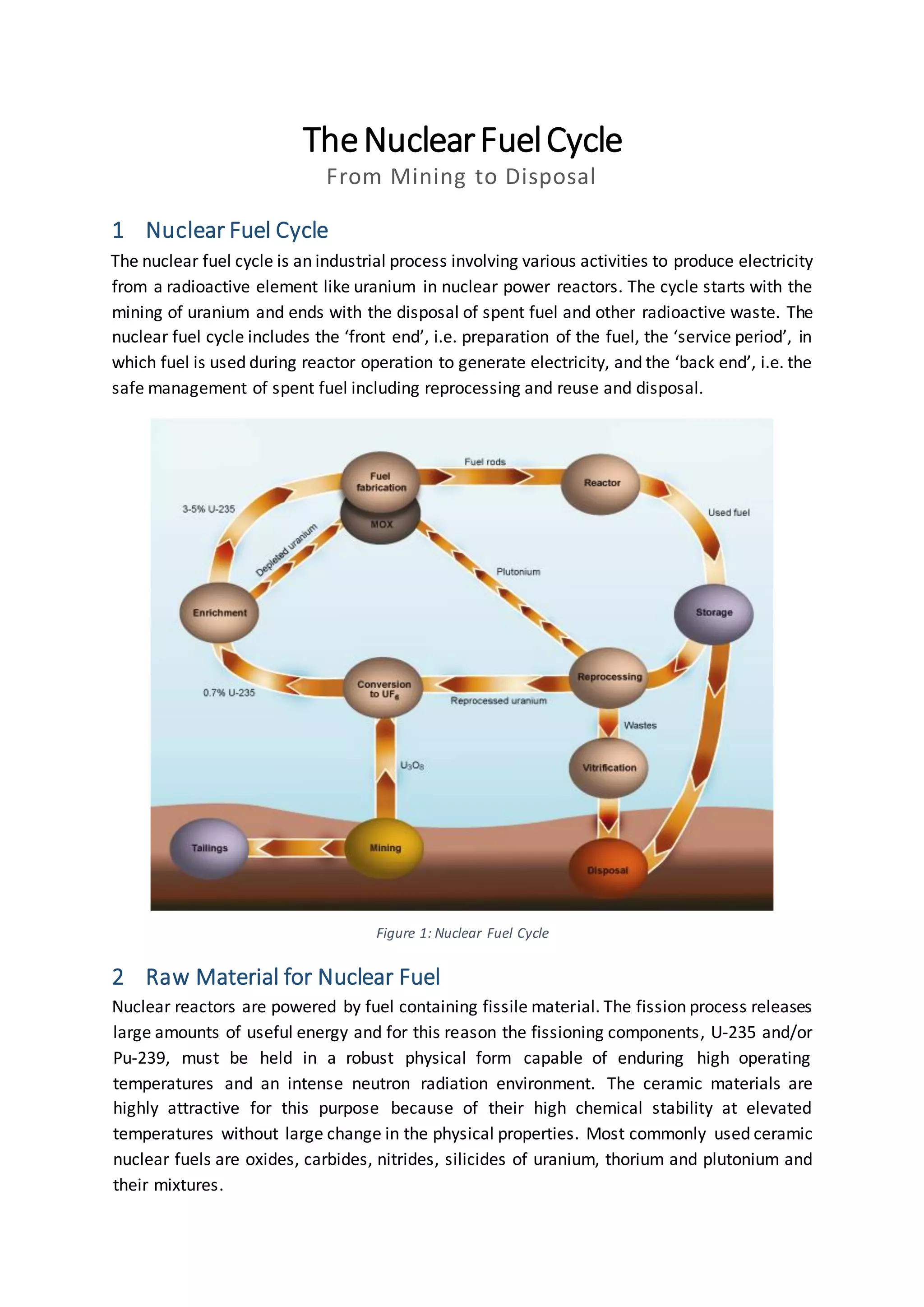
TheNuclearFuelCycle
From Mining to Disposal
1 Nuclear Fuel Cycle
The nuclear fuel cycle is an industrial process involving various activities to produce electricity
from a radioactive element like uranium in nuclear power reactors. The cycle starts with the
mining of uranium and ends with the disposal of spent fuel and other radioactive waste. The
nuclear fuel cycle includes the ‘front end’, i.e. preparation of the fuel, the ‘service period’, in
which fuel is used during reactor operation to generate electricity, and the ‘back end’, i.e. the
safe management of spent fuel including reprocessing and reuse and disposal.
2 Raw Material for Nuclear Fuel
Nuclear reactors are powered by fuel containing fissile material. The fission process releases
large amounts of useful energy and for this reason the fissioning components, U-235 and/or
Pu-239, must be held in a robust physical form capable of enduring high operating
temperatures and an intense neutron radiation environment. The ceramic materials are
highly attractive for this purpose because of their high chemical stability at elevated
temperatures without large change in the physical properties. Most commonly used ceramic
nuclear fuels are oxides, carbides, nitrides, silicides of uranium, thorium and plutonium and
their mixtures.
Figure 1: Nuclear Fuel Cycle
Potential advantages of ceramic fuels are:
• Good irradiation stability (no phase transition)
• Higher fuel and plant operating temperature (higher melting temp. than metals)
• Excellent corrosion resistance
• Low thermal expansion coefficient
Disadvantages of ceramic fuels are:
• Brittle, low fracture strength
• Poor heat transfer to cladding (no
metallurgical bond)
• Poor thermal conductivity, as
illustrated below (especially UO2)
Though ceramic fuel has some
disadvantages, its advantages override them
and makes ceramic fuel the potential
contender for nuclear fuel.
The raw material for today’s nuclear fuel is
uranium, which is a relatively common metal
that can be found throughout the world.
Uranium is present in most rocks and soils, in many rivers and in sea water. Uranium is about
500 times more abundant than gold and about as common as tin. The three main ceramic
nuclear fuels are UO2, UC and UN, although UO2 is most commonly used.
3 Uranium Dioxide (UO2)
UO2 is a precursor to U metal and was first used as a blanket fuel, resistant to high-
temperature water. A blanket fuel is a layer of material containing fertile isotopes that is
placed around the reactor core as a reflector or absorber, but which is also used to breed
additional fissionable material – it therefore reduces neutron leakage whilst absorbing
neutrons and breeding more fuel. However, it is now very well studied, and has been in
reliable useas a nuclear fuel for nearly 50 years. In UO2 fuel, either natural or slightlyenriched
uranium (0.7– 4%) can be used. Note that fast Breeder Reactors use a mixed oxide, MOX:
(U0.75Pu0.25)O2. The oxides UO2 and PuO2 show complete mutual solubility as illustrated in the
following figure.
Figure 2: Thermal Conductivity of Major Nuclear Fuels
Figure 3: Solidus and Liquidus Lines in the UO2 - PuO2 Equilibrium Phase Diagram
4 Processing Stages of UO2
The processing of ceramic nuclear fuel includes the following steps:
1. Mining & Milling (from Mined Uranium to Yellow Cake)
2. Conversion from Yellow Cake to Gas
3. Enriching Proportion of Fissile Isotope
4. Fabrication of Fuel (Ceramic Pellets)
4.1 Mining& Milling:(Mined Uranium to YellowCake)
Uranium ore can come from a mine specifically for uranium, or as a byproduct from mines
with a different main product such as Cu or gold.
• The mined uranium ore is crushed and chemically treated to separate the Uranium,
usually by the addition of acid or alkali. The remaining crushed rock called ‘tailings’
must be appropriately disposed of.
• Alternatively, for in situ leach mining, acidic or alkaline mining solution is passed
directly through the underground ore body via a series of bores or wells and uranium
is brought to the surface in a dissolved state for purification. No tailings are produced
by this method.
• The final result is ‘yellow cake’, a powder form of uranium oxide (U3O8) or similar
compounds. In yellow cake, the uranium concentration is raised to more than 80%.
4.2 Conversion from YellowCake to Gas
Conversion is a process in which the uranium is converted to a form suitable either for fuel
fabrication or enrichment.
• The yellow cake (U3O8) is converted to uranium dioxide (UO2) at the conversion plant
where enriched uranium is not required.
• As most power plants require enriched uranium, it requires the material to be in the
gaseous form. So, the yellow cake is converted into uranium hexafluoride (UF6) gas.
• UF6 is a gas at relatively low temperature. The gas is fed into large cylinders where it
solidifies. The cylinders are loaded into strong metal containers and shipped to an
enrichment plant.
4.3 EnrichingProportionof FissileIsotope
Natural uranium consists primarily of two isotopes: 99.3% is 238U and 0.7% is 235U. The
fission process, by which heat energy is released in a nuclear reactor, takes place mainly
with 235U. As most nuclear power plants require fuel with a 235U concentration of 3–5%, the
proportion of 235U isotope must be increased to 3–5%. This process is known as enrichment.
• Gaseous diffusion – involves forcing gaseous UF6 through semi-permeable
membranes to produce a slight separation between the molecules containing 235U
and 238U.
• Gas centrifuge – involves many rotating cylinders in series and parallel formations -
heavier gas molecules containing 238U move towards the outside of the cylinder and
the lighter gas molecules rich in 235U collect closer to the center.
The gas centrifuge method requires much less energy to achieve the same separation than
the gaseous diffusion process, so is now the method of choice.
If enriched uranium is used in a fission reactor, it is good practice to vary the enrichment
across the core. This is because irradiation is usually non-uniform: it tends to be higher in
the center of the reactor (and also higher in the center of a fuel rod), so having a varying
Figure 5: Gaseous Diffusion Figure 4: Gas Centrifuge
enrichment across the reactor core can allow burn-up to occur more evenly. Enrichment also
helps sustain the chain reaction.
However, the main disadvantage of using enriched uranium is the high cost associated with
the enrichment. It is difficult to separate two isotopes of the same element, because they
have very nearly identical chemical properties and only a very small mass difference.
4.4 Fabrication of Fuel (Ceramic Pellets)
The fabrication of fuel structures – called assemblies or bundles – is the last stage of the front
end of the nuclear cycle. All of the current generation of power reactors use uranium
dioxide(UO2) fuel in the form of ceramic pellets. Pellets are usually used, since it is difficult to
manufacture a whole fuel rod from a ceramic.
With a melting point around 2800°C, ceramic pellets can operate at high temperatures. They
are also a ‘barrier’ containing radioactivity within the reactor fuel. One uranium pellet
contains approximately the same amount of energy as 800 kg of coal or 560 L of oil.
A high density of the final product is desirable to ensure a high density of fissile or fissionable
atoms, and good thermal conductivity. However, some residual porosity is useful to retain
fission product gases and to allow densification on heating to offset irradiation swelling.
4.4.1 ProcessOverview of Fabrication in Powder Metallurgy Method
There are three main stages in the fabrication of the nuclear fuel structures used in LWRs
(Light Water Reactor) and PHWRs (Pressurized Heavy Water Reactor):
1.Producing pure uranium dioxide (UO2) from incoming UF6 or UO3.
2.Producing high-density, accurately shaped ceramic UO2 pellets.
3.Producing the rigid metal framework for the fuel assembly.
Figure 6: The Fuel Fabrication Process
4.4.1.1 UO2 Powder Production
Uranium arrives at a fuel manufacturing plant in one of two forms, uranium hexafluoride (UF6)
or uranium trioxide (UO3), depending on whether it has been enriched or not. It needs to be
converted to uranium dioxide (UO2) prior to pellet fabrication. Most fabrication plants have
their own facilities for effecting this chemical conversion (some do not, and acquire UO2 from
plants with excess conversion capacity). Chemical conversion to and from UF6 are distinct
processes, but both involve the handling of aggressive fluorine compounds and plants may
be set up to do both.
Conversion to UO2 canbe done using ‘dry’ or ‘wet’ processes.In the dry method, UF6 is heated
to a vapor and introduced into a two stage reaction vessel (e.g., rotary kiln) where it is first
mixed with steam to produce solid uranyl fluoride (UO2F2) – this powder moves through the
vessel to be reacted with H2 (diluted in steam) which removes the fluoride and chemically
reduces the uranium to a pure microcrystalline UO2 product.
Wet methods involve the injection of UF6 into water to form a UO2F2 particulate slurry. Either
ammonia (NH3) or ammonium carbonate (NH3)2CO3) is added to this mixture and the UO2F2
reacts to produce; ammonium diuranate (ADU, (NH3)2U2O7) in the first case, or ammonium
uranyl carbonate (AUC, UO2CO3.(NH3)2CO3) in the latter case. In both cases the slurry is
filtered, dried and heated in a reducing atmosphere to pure UO2. The morphology of UO2
powders deriving from the ADU and AUC routes are different, and this has a bearing on final
pellet microstructure.
Wet methods are slightly more complex and give rise to more wastes. However, the
advantage is its greater flexibility in terms of UO2 powder properties.
For the conversion of UO3 to UO2, water is added to UO3 so that it forms a hydrate. This solid
is fed (wet or dry) into a kiln operating with a reducing atmosphere and UO2 is produced.
4.4.2 Manufactureof Ceramic UO2 Pellets
The UO2 powder may need further processing or conditioning before it can be formed into
pellets:
•Homogenization: powders may need to be blended to ensure uniformity in terms of
particle size distribution and specific surface area.
•Additives: U3O8 may be added to ensure satisfactory microstructure and density for
the pellets. Other fuel ingredients, such as lubricants, burnable absorbers (e.g. gadolinium)
and pore-formers may also need to be added.
Conditioned UO2 powder is fed into dies and pressed biaxiallyinto cylindricalpellet form using
a load of several hundred MPa – this is done in pressing machines operating at high speed.
These ‘green’ pellets are then sintered by heating in a furnace at about 1750°C under a
precisely controlled reducing atmosphere (usually argon-hydrogen) in order to consolidate
them. This also has the effect of decreasing their volume. The pellets are then machined to
exact dimensions – the scrap from which being fed back into an earlier stage of the process.
Rigorous quality control is applied to ensure pellet integrity and precise dimensions.
Burnable absorbers such as gadoliniummay be incorporated (as oxide) into the fuel pellets of
some rods to limit reactivity early in the life of the fuel. Burnable absorbers have a very high
neutron absorption cross-section and compete strongly for neutrons. After that they
progressively ‘burn-out’ and convert into nuclides with low neutron absorption; leaving fissile
(U-235) to react with neutrons. Burnable absorbers enable longer fuel life by allowing higher
fissile enrichment in fresh fuel.
4.4.3 Rigid Metal Frameworkfor the Fuel Assembly
The framework is mainly manufactured from zirconium alloy. The fuel pellets are loaded into
the fuel rods. The rods are then sealed and assembled into the final fuel assembly structure.
4.5 AlternativeRouteof UO2 Production: Sol-GelProcess
Fabrication of UO2 pellets using powder metallurgical process is a very well established route.
However, the following problems are associated with the powder metallurgical route.
1. Handling of large quantity of highly toxic radioactive powders.
2. Large number of mechanical steps in the fuel fabrication flow sheet.
3. Difficulties in remotisation of the process as a consequence of the above.
4. Increase in the man-rem problems with the aging of the fabrication facility because
of 241Ambuilt up.
To avoid the drawbacks Sol-Gel process have been selected for fabricating 233U fuels. The
name Sol-Gel process is ageneralized heading for chemicalroutes which involves the gelation
of a droplet of sol or solution of the desired fuel material into a gel microsphere. These are
washed, dried and heat treated to obtain high density microsphere.
4.5.1 Advantagesof Sol-GelProcess
Theseprocesses offer a largenumber of advantages over the conventional powder route. Sol-
Gel processes do not require handling of radioactive powders and involve handling of fluids
or fluid like materials which are ideally suited for the remote handling. These processes also
minimize the number of mechanical operations and thus reduce the man-rem problems.
4.5.2 SGMP Process(Sol-GelMicrosphere Palletization)
SGMP process uses the solutions of the nitrates of uranium, thorium and plutonium or their
desired mixtures. The cooled (~ 0oC) metal nitrate solutions are mixed with urea and HMTA
(hexamethylenetetramine) solution in cooled condition (~ 0oC). The droplets of this mixture
are contacted with hot silicone oil (~90 oC) to make gel microspheres.
These gel microspheres are washed first with CCl4 to remove the silicone oil and then with
NH4OH solution to remove excess gelation agents − HMTA, urea and ammonium nitrate. The
washed particles are dried at 100oC in air and then calcined up to 800oC to remove residual
organic matter and ammonium nitrate. The calcined microspheres are then reduced in N2+H2
mixture at 600oC. The UO2 microspheres thus produced are sintered at 1250oC for 3 hours in
CO atmosphere to produce > 98% TD microspheres.
5 Electricity Generation
A nuclear power plant produces electricity by heating water to generate steam that makes
the turbine rotate to enable the generator to produce electricity.
A nuclear power plant produces electricity by heating water to generate steam that makes
the turbine rotate to enable the generator to produce electricity. The significant difference
between fossil fuel and nuclear power plants is the source of heat. In a fossil fuel plant, the
heat is produced by burning gas or coal. In a nuclear plant, the heat is generated by the fission
of some of the uranium in the nuclear fuel assemblies.
When the nucleus of an atom of, for example, 235U absorbs a neutron, it may split (or fission)
into two pieces, giving off energy as heat and a few more neutrons to continue this nuclear
chain reaction. This chain reaction is controlled to produce exactly the desired amount of
energy.
6 SpentFuel Storage
After their useful life of 3–6 years, fuel assemblies are removed from the reactor. After their
permanent removal, they are stored under water, which provides both cooling and radiation
shielding. Later, for longer term storage, spent fuel assemblies can be moved to another pool
for wet storage or to air-cooled, shielded buildings or casks for dry storage. Both the heat and
Figure 8: Flowchart of SGMP Process
Figure 7: Stages of SGMP for UO2 Pellets
radioactivity decrease over time. After 40 years in storage, the spent fuel’s radioactivity will
be about a thousand times lower than when it was permanently removed from the reactor.
7 Reprocessing Spent Fuel
The spent fuel contains uranium (about 96%), plutonium (about 1%) and highlevel radioactive
waste products (about 3%). The uranium, with less than 1% fissile 235U, and the plutonium
can be reused. Current reprocessing plants dissolve the spent fuel and chemically separate it
into those three components: uranium, plutonium and high level waste.
Much like freshly mined uranium, the uranium recovered by reprocessing can be converted
to UF6 and re-enriched, returning to the fuel cycle as ‘recovered uranium’.
The plutonium can be mixed with uranium and used to fabricate mixed oxide fuel (MOX) for
nuclear reactors. The use of plutonium, through MOX fuel, reduces the need for enrichment
and the production of depleted uranium.
The high level waste is vitrified, or converted into a glass, to be disposed of in a high level
waste disposal facility.
Approximately one third of the fuel discharged from nuclear reactors is reprocessed.
8 Managing Radioactive Waste
In broad terms, radioactive waste is grouped into low, intermediate and high level waste.
Spent fuel (when declared as waste) and high level waste can be safely disposed of deep
underground, in stable rock formations such as granite, thus eliminating the health risk to
people and protecting the environment. This waste will be packed in durable containers and
buried deep in geological formations chosen for their favorable stability and geochemistry,
including limited water movement. Low and intermediate level waste is not disposed of
conventionally as normal refuse but is carefully segregated, measured for radioactivity and
placed into engineered and monitored waste disposal facilities.

Nuclear Fuel Cycle

  • 1.
    TheNuclearFuelCycle From Mining toDisposal 1 Nuclear Fuel Cycle The nuclear fuel cycle is an industrial process involving various activities to produce electricity from a radioactive element like uranium in nuclear power reactors. The cycle starts with the mining of uranium and ends with the disposal of spent fuel and other radioactive waste. The nuclear fuel cycle includes the ‘front end’, i.e. preparation of the fuel, the ‘service period’, in which fuel is used during reactor operation to generate electricity, and the ‘back end’, i.e. the safe management of spent fuel including reprocessing and reuse and disposal. 2 Raw Material for Nuclear Fuel Nuclear reactors are powered by fuel containing fissile material. The fission process releases large amounts of useful energy and for this reason the fissioning components, U-235 and/or Pu-239, must be held in a robust physical form capable of enduring high operating temperatures and an intense neutron radiation environment. The ceramic materials are highly attractive for this purpose because of their high chemical stability at elevated temperatures without large change in the physical properties. Most commonly used ceramic nuclear fuels are oxides, carbides, nitrides, silicides of uranium, thorium and plutonium and their mixtures. Figure 1: Nuclear Fuel Cycle
  • 2.
    Potential advantages ofceramic fuels are: • Good irradiation stability (no phase transition) • Higher fuel and plant operating temperature (higher melting temp. than metals) • Excellent corrosion resistance • Low thermal expansion coefficient Disadvantages of ceramic fuels are: • Brittle, low fracture strength • Poor heat transfer to cladding (no metallurgical bond) • Poor thermal conductivity, as illustrated below (especially UO2) Though ceramic fuel has some disadvantages, its advantages override them and makes ceramic fuel the potential contender for nuclear fuel. The raw material for today’s nuclear fuel is uranium, which is a relatively common metal that can be found throughout the world. Uranium is present in most rocks and soils, in many rivers and in sea water. Uranium is about 500 times more abundant than gold and about as common as tin. The three main ceramic nuclear fuels are UO2, UC and UN, although UO2 is most commonly used. 3 Uranium Dioxide (UO2) UO2 is a precursor to U metal and was first used as a blanket fuel, resistant to high- temperature water. A blanket fuel is a layer of material containing fertile isotopes that is placed around the reactor core as a reflector or absorber, but which is also used to breed additional fissionable material – it therefore reduces neutron leakage whilst absorbing neutrons and breeding more fuel. However, it is now very well studied, and has been in reliable useas a nuclear fuel for nearly 50 years. In UO2 fuel, either natural or slightlyenriched uranium (0.7– 4%) can be used. Note that fast Breeder Reactors use a mixed oxide, MOX: (U0.75Pu0.25)O2. The oxides UO2 and PuO2 show complete mutual solubility as illustrated in the following figure. Figure 2: Thermal Conductivity of Major Nuclear Fuels
  • 3.
    Figure 3: Solidusand Liquidus Lines in the UO2 - PuO2 Equilibrium Phase Diagram 4 Processing Stages of UO2 The processing of ceramic nuclear fuel includes the following steps: 1. Mining & Milling (from Mined Uranium to Yellow Cake) 2. Conversion from Yellow Cake to Gas 3. Enriching Proportion of Fissile Isotope 4. Fabrication of Fuel (Ceramic Pellets) 4.1 Mining& Milling:(Mined Uranium to YellowCake) Uranium ore can come from a mine specifically for uranium, or as a byproduct from mines with a different main product such as Cu or gold. • The mined uranium ore is crushed and chemically treated to separate the Uranium, usually by the addition of acid or alkali. The remaining crushed rock called ‘tailings’ must be appropriately disposed of. • Alternatively, for in situ leach mining, acidic or alkaline mining solution is passed directly through the underground ore body via a series of bores or wells and uranium is brought to the surface in a dissolved state for purification. No tailings are produced by this method. • The final result is ‘yellow cake’, a powder form of uranium oxide (U3O8) or similar compounds. In yellow cake, the uranium concentration is raised to more than 80%.
  • 4.
    4.2 Conversion fromYellowCake to Gas Conversion is a process in which the uranium is converted to a form suitable either for fuel fabrication or enrichment. • The yellow cake (U3O8) is converted to uranium dioxide (UO2) at the conversion plant where enriched uranium is not required. • As most power plants require enriched uranium, it requires the material to be in the gaseous form. So, the yellow cake is converted into uranium hexafluoride (UF6) gas. • UF6 is a gas at relatively low temperature. The gas is fed into large cylinders where it solidifies. The cylinders are loaded into strong metal containers and shipped to an enrichment plant. 4.3 EnrichingProportionof FissileIsotope Natural uranium consists primarily of two isotopes: 99.3% is 238U and 0.7% is 235U. The fission process, by which heat energy is released in a nuclear reactor, takes place mainly with 235U. As most nuclear power plants require fuel with a 235U concentration of 3–5%, the proportion of 235U isotope must be increased to 3–5%. This process is known as enrichment. • Gaseous diffusion – involves forcing gaseous UF6 through semi-permeable membranes to produce a slight separation between the molecules containing 235U and 238U. • Gas centrifuge – involves many rotating cylinders in series and parallel formations - heavier gas molecules containing 238U move towards the outside of the cylinder and the lighter gas molecules rich in 235U collect closer to the center. The gas centrifuge method requires much less energy to achieve the same separation than the gaseous diffusion process, so is now the method of choice. If enriched uranium is used in a fission reactor, it is good practice to vary the enrichment across the core. This is because irradiation is usually non-uniform: it tends to be higher in the center of the reactor (and also higher in the center of a fuel rod), so having a varying Figure 5: Gaseous Diffusion Figure 4: Gas Centrifuge
  • 5.
    enrichment across thereactor core can allow burn-up to occur more evenly. Enrichment also helps sustain the chain reaction. However, the main disadvantage of using enriched uranium is the high cost associated with the enrichment. It is difficult to separate two isotopes of the same element, because they have very nearly identical chemical properties and only a very small mass difference. 4.4 Fabrication of Fuel (Ceramic Pellets) The fabrication of fuel structures – called assemblies or bundles – is the last stage of the front end of the nuclear cycle. All of the current generation of power reactors use uranium dioxide(UO2) fuel in the form of ceramic pellets. Pellets are usually used, since it is difficult to manufacture a whole fuel rod from a ceramic. With a melting point around 2800°C, ceramic pellets can operate at high temperatures. They are also a ‘barrier’ containing radioactivity within the reactor fuel. One uranium pellet contains approximately the same amount of energy as 800 kg of coal or 560 L of oil. A high density of the final product is desirable to ensure a high density of fissile or fissionable atoms, and good thermal conductivity. However, some residual porosity is useful to retain fission product gases and to allow densification on heating to offset irradiation swelling. 4.4.1 ProcessOverview of Fabrication in Powder Metallurgy Method There are three main stages in the fabrication of the nuclear fuel structures used in LWRs (Light Water Reactor) and PHWRs (Pressurized Heavy Water Reactor): 1.Producing pure uranium dioxide (UO2) from incoming UF6 or UO3. 2.Producing high-density, accurately shaped ceramic UO2 pellets. 3.Producing the rigid metal framework for the fuel assembly. Figure 6: The Fuel Fabrication Process 4.4.1.1 UO2 Powder Production Uranium arrives at a fuel manufacturing plant in one of two forms, uranium hexafluoride (UF6) or uranium trioxide (UO3), depending on whether it has been enriched or not. It needs to be
  • 6.
    converted to uraniumdioxide (UO2) prior to pellet fabrication. Most fabrication plants have their own facilities for effecting this chemical conversion (some do not, and acquire UO2 from plants with excess conversion capacity). Chemical conversion to and from UF6 are distinct processes, but both involve the handling of aggressive fluorine compounds and plants may be set up to do both. Conversion to UO2 canbe done using ‘dry’ or ‘wet’ processes.In the dry method, UF6 is heated to a vapor and introduced into a two stage reaction vessel (e.g., rotary kiln) where it is first mixed with steam to produce solid uranyl fluoride (UO2F2) – this powder moves through the vessel to be reacted with H2 (diluted in steam) which removes the fluoride and chemically reduces the uranium to a pure microcrystalline UO2 product. Wet methods involve the injection of UF6 into water to form a UO2F2 particulate slurry. Either ammonia (NH3) or ammonium carbonate (NH3)2CO3) is added to this mixture and the UO2F2 reacts to produce; ammonium diuranate (ADU, (NH3)2U2O7) in the first case, or ammonium uranyl carbonate (AUC, UO2CO3.(NH3)2CO3) in the latter case. In both cases the slurry is filtered, dried and heated in a reducing atmosphere to pure UO2. The morphology of UO2 powders deriving from the ADU and AUC routes are different, and this has a bearing on final pellet microstructure. Wet methods are slightly more complex and give rise to more wastes. However, the advantage is its greater flexibility in terms of UO2 powder properties. For the conversion of UO3 to UO2, water is added to UO3 so that it forms a hydrate. This solid is fed (wet or dry) into a kiln operating with a reducing atmosphere and UO2 is produced. 4.4.2 Manufactureof Ceramic UO2 Pellets The UO2 powder may need further processing or conditioning before it can be formed into pellets: •Homogenization: powders may need to be blended to ensure uniformity in terms of particle size distribution and specific surface area. •Additives: U3O8 may be added to ensure satisfactory microstructure and density for the pellets. Other fuel ingredients, such as lubricants, burnable absorbers (e.g. gadolinium) and pore-formers may also need to be added. Conditioned UO2 powder is fed into dies and pressed biaxiallyinto cylindricalpellet form using a load of several hundred MPa – this is done in pressing machines operating at high speed. These ‘green’ pellets are then sintered by heating in a furnace at about 1750°C under a precisely controlled reducing atmosphere (usually argon-hydrogen) in order to consolidate them. This also has the effect of decreasing their volume. The pellets are then machined to exact dimensions – the scrap from which being fed back into an earlier stage of the process. Rigorous quality control is applied to ensure pellet integrity and precise dimensions. Burnable absorbers such as gadoliniummay be incorporated (as oxide) into the fuel pellets of some rods to limit reactivity early in the life of the fuel. Burnable absorbers have a very high neutron absorption cross-section and compete strongly for neutrons. After that they progressively ‘burn-out’ and convert into nuclides with low neutron absorption; leaving fissile
  • 7.
    (U-235) to reactwith neutrons. Burnable absorbers enable longer fuel life by allowing higher fissile enrichment in fresh fuel. 4.4.3 Rigid Metal Frameworkfor the Fuel Assembly The framework is mainly manufactured from zirconium alloy. The fuel pellets are loaded into the fuel rods. The rods are then sealed and assembled into the final fuel assembly structure. 4.5 AlternativeRouteof UO2 Production: Sol-GelProcess Fabrication of UO2 pellets using powder metallurgical process is a very well established route. However, the following problems are associated with the powder metallurgical route. 1. Handling of large quantity of highly toxic radioactive powders. 2. Large number of mechanical steps in the fuel fabrication flow sheet. 3. Difficulties in remotisation of the process as a consequence of the above. 4. Increase in the man-rem problems with the aging of the fabrication facility because of 241Ambuilt up. To avoid the drawbacks Sol-Gel process have been selected for fabricating 233U fuels. The name Sol-Gel process is ageneralized heading for chemicalroutes which involves the gelation of a droplet of sol or solution of the desired fuel material into a gel microsphere. These are washed, dried and heat treated to obtain high density microsphere. 4.5.1 Advantagesof Sol-GelProcess Theseprocesses offer a largenumber of advantages over the conventional powder route. Sol- Gel processes do not require handling of radioactive powders and involve handling of fluids or fluid like materials which are ideally suited for the remote handling. These processes also minimize the number of mechanical operations and thus reduce the man-rem problems. 4.5.2 SGMP Process(Sol-GelMicrosphere Palletization) SGMP process uses the solutions of the nitrates of uranium, thorium and plutonium or their desired mixtures. The cooled (~ 0oC) metal nitrate solutions are mixed with urea and HMTA (hexamethylenetetramine) solution in cooled condition (~ 0oC). The droplets of this mixture are contacted with hot silicone oil (~90 oC) to make gel microspheres. These gel microspheres are washed first with CCl4 to remove the silicone oil and then with NH4OH solution to remove excess gelation agents − HMTA, urea and ammonium nitrate. The washed particles are dried at 100oC in air and then calcined up to 800oC to remove residual organic matter and ammonium nitrate. The calcined microspheres are then reduced in N2+H2 mixture at 600oC. The UO2 microspheres thus produced are sintered at 1250oC for 3 hours in CO atmosphere to produce > 98% TD microspheres.
  • 8.
    5 Electricity Generation Anuclear power plant produces electricity by heating water to generate steam that makes the turbine rotate to enable the generator to produce electricity. A nuclear power plant produces electricity by heating water to generate steam that makes the turbine rotate to enable the generator to produce electricity. The significant difference between fossil fuel and nuclear power plants is the source of heat. In a fossil fuel plant, the heat is produced by burning gas or coal. In a nuclear plant, the heat is generated by the fission of some of the uranium in the nuclear fuel assemblies. When the nucleus of an atom of, for example, 235U absorbs a neutron, it may split (or fission) into two pieces, giving off energy as heat and a few more neutrons to continue this nuclear chain reaction. This chain reaction is controlled to produce exactly the desired amount of energy. 6 SpentFuel Storage After their useful life of 3–6 years, fuel assemblies are removed from the reactor. After their permanent removal, they are stored under water, which provides both cooling and radiation shielding. Later, for longer term storage, spent fuel assemblies can be moved to another pool for wet storage or to air-cooled, shielded buildings or casks for dry storage. Both the heat and Figure 8: Flowchart of SGMP Process Figure 7: Stages of SGMP for UO2 Pellets
  • 9.
    radioactivity decrease overtime. After 40 years in storage, the spent fuel’s radioactivity will be about a thousand times lower than when it was permanently removed from the reactor. 7 Reprocessing Spent Fuel The spent fuel contains uranium (about 96%), plutonium (about 1%) and highlevel radioactive waste products (about 3%). The uranium, with less than 1% fissile 235U, and the plutonium can be reused. Current reprocessing plants dissolve the spent fuel and chemically separate it into those three components: uranium, plutonium and high level waste. Much like freshly mined uranium, the uranium recovered by reprocessing can be converted to UF6 and re-enriched, returning to the fuel cycle as ‘recovered uranium’. The plutonium can be mixed with uranium and used to fabricate mixed oxide fuel (MOX) for nuclear reactors. The use of plutonium, through MOX fuel, reduces the need for enrichment and the production of depleted uranium. The high level waste is vitrified, or converted into a glass, to be disposed of in a high level waste disposal facility. Approximately one third of the fuel discharged from nuclear reactors is reprocessed. 8 Managing Radioactive Waste In broad terms, radioactive waste is grouped into low, intermediate and high level waste. Spent fuel (when declared as waste) and high level waste can be safely disposed of deep underground, in stable rock formations such as granite, thus eliminating the health risk to people and protecting the environment. This waste will be packed in durable containers and buried deep in geological formations chosen for their favorable stability and geochemistry, including limited water movement. Low and intermediate level waste is not disposed of conventionally as normal refuse but is carefully segregated, measured for radioactivity and placed into engineered and monitored waste disposal facilities.