
Recommended
Recommended
More Related Content
What's hot
What's hot (20)
Similar to Vocational Training Report on 4260 MW Vindhyachal Super Thermal Power Plant
Similar to Vocational Training Report on 4260 MW Vindhyachal Super Thermal Power Plant (20)
More from Vinay Vishwakarma
Recently uploaded
Recently uploaded (20)
Vocational Training Report on 4260 MW Vindhyachal Super Thermal Power Plant
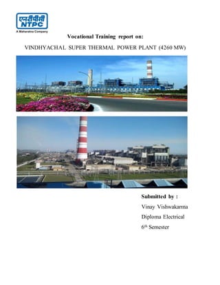
- 1. Vocational Training report on: VINDHYACHAL SUPER THERMAL POWER PLANT (4260 MW) Submitted by : Vinay Vishwakarma Diploma Electrical 6th Semester
- 2. Acknowledgement With deep reverence and profound gratitude I express my sincere thanks to Mr. Atul Markhedkar, AGM (EMD) for giving me an opportunity to do training at NTPC/VSTPP. Ialso would like to thank Mr. K.L. Barange, (EMD) who has helped me at the working sites, explaining and giving me all the information I needed to complete this report. I am also very much thankful to Mr. Vishnu Sen Assistant General Manager(EMD), for helping me throughout the training. At last I would like to convey my thanks to all the members of the staff of NTPC who have helped me at every stage of training. Training Period: 30 Jan 2015 to 13 Feb 2015.
- 3. INTRODUCTION NTPC is the largest thermal power generating company of India. Vindhyachal Thermal Power Plant is located in Singrauli at the state of Madhya Pradesh. This Power station is one of the coal based plant of NTPC. It is one of the largest power stations in India with installed capacity 4260 MW and one unit is in under construction. The Coal is sourced from Nigahi Coal Mines and Dudhichua Mines. Sourceof Water is taken from discharge of Singrauli Super Thermal Power Plant. The first unit of 210 MW plant is commissioned in 1987 by Russian support. Total land acquired is 6178 acres. PROJECT COST The approved costof Stage-I (6X210 MW) is Rs. 1460.37 crore with the per financing by erstwhile USSR assistance amounting to 303.66 Million rouble. The approved costof stage-II (2 X500 MW) is Rs. 2702 Crore. International assistance from IBRD time-slice loan of US $ 400 Million has been utilized for part financing of stage-II. The approved costof stage-III (2 X 500 MW) is Rs.4125.00 Cr. Vindhyachal is accredited with ESHQ (Environment Safety Health & Quality) for following Environment management systems, Safety & Occupational Health management systems & Quality management systems.
- 4. Stage Unit Number Capacity (MW) Date of Commissioning 1st 1 210 1987 October 1st 2 210 1988 July 1st 3 210 1989 February 1st 4 210 1989 December 1st 5 210 1990 March 1st 6 210 1991 February 2nd 7 500 1999 March 2nd 8 500 2000 February 3rd 9 500 2006 July 3rd 10 500 2007 March 4th 11 500 2012 June 4th 12 500 2013 April 5th 13 500 Under construction Total Thirteen 4760 5th stage is in under construction will complete on January 2016.
- 5. FLOW CHART OF 210 MW VINDHYACHAL SUPER THERMAL POWER STATION Power plant is divided into 3 cycle, they are:- 1. Fuel Cycle 2. Water Cycle 3. Steam Cycle FUEL CYCLE 1. Coal Preparation from coal mill to boiler : Fuel Preparation system: In coalpower plant, the raw feed coal from the coal storage area is first crushed into small pieces and then with the help of conveyor belt , it transfer to the hopper at the boiler. The coal is next pulverized into a very fine powder, So that coal will undergo complete combustionduring combustion process.
- 6. ** Pulverizer is a mechanical devices for the grinding of many different types of materials. Forexample Coal is converted into Powder form. 2. Dryers : This is used to remove moisture from coal mainly wetted during transport. Presence of moisture in coal will result fall in efficiency of a plant and also emit CO gas. 3. Magnetic Separator : It is used to separate the coal and magnetic material like Iron or any other metal which is going to coalmill. INDUCTION MOTOR used in COAL MILL Duty Continuous KW 525 Stator Volts 3300 StatorAmps 129 RPM 984 Frequency Hz 50 Phase 3 Power factor 0.9 Weight 5750 Kg Rotortype Squirrel Cage ECONOMISER It is located below the LPSH in the boiler and above preheater. It is there to improve the efficiency of boiler by extracting heat from flue gases to heat water and send it to boiler drum. Advantages of its :- a. Fuel economy- used to save fuel & increase overall efficiency of boiler plant.
- 7. b. Reducing size of boiler- as the feed water is preheated in the economizer & enter boiler tube at elevate temperature. HEATER’S 1. Air Preheater – The heat taken out with the flue gases. It is a necessary equipment for supply of hot air for drying the coal in pulverized fuel systems to facilitate grinding and satisfactory combustion of fuel in the furnace. 2. Reheater- this section containing tubes heated by hot flue gases outsides the tubes. Exhaust steam from the high pressure turbine is rerouted to go inside the reheater tubes to pick up more energy to go drive intermediate or lower pressure turbines. 3. Platen Superheater- Flat panels of tubes located in the upper part of the furnace, where the gas temperature is high and receive very high radiation as well as a heavy dust burden. PLATEN SUPERHEATER AIR PREHEATER The major Fan used in this plant are :- 4. Induced Draught Fan : The main function of the ID FAN is to suck the flue gases coming out of the furnace via economizer, air heater and also collect the ash particles and release into a atmosphere with the help of chimney. Synchronous Motor is used in ID fan and rating are :-
- 8. KW -4525, PF-0.95 lead ,RPM- 580, Stator Volt -2*2300, Exct. Volt - 87 V, Insln class- F, Phase -2*3, Hz -48.33, Connection- double star, Stator amps- 2*622 A, Weight -31000 kg. 5. Forced Draught Fan :For the burning of any substanceOxygen in needed. In that way FD fan provides the Oxygen inside a boiler by which the coal continuously burn and heats the water to convert into steam. Induction Motor is used in FD fan Duty – Continuous, KW – 1650, Stator volts – 11000, Stator amps- 106, RPM- 996, Phase-3, stator connection- star, Rotorconnection- -, Rotortype- Cage, Insulation class-F, Weight- 11500 kg, Year- 2013. 6. Primary Air Fan : The main purposeof this fan is to create high pressure to send pulverize coalinto the boiler to producea heat. Induction motor is used in PA fan Duty-Continuous, KW- 3500, Stator volt-11000, Stator amps-211, RPM-1495, Phase-3, Hz-50, Insln class- F, PF-0.90 lag, efficiency-96.7%, Weight-15500 kg, Rotortype- Cage type, Stator connection – star, RotorConn- . FD fan PA fan
- 9. ELECTROSTATIC PRECIPITATOR An Electrostatic Precipitator is a filtration device that removes fine particles, like dust and smoke , from a flowing gas. WATER CYCLE HOT WELL OR STORAGE TANK Hot well is storage tank where the water is stored and from where the water cycle is starts. It is also a place where condensewater finally comes .After the steam process , hot water is discharge from here and taken out to cooling tower and then the water is suck by Hot well .And the process continues. Condensate Extract Pump CEP: A CEP is a specific type of pump used to pump feed water into a steam boiler and also rising the temperature and pressure of a water. Main Ejector : The injector was originally used in the boilers of steamlocomotives for injecting or pumping the boilerfeedwater into the boiler. Low Pass Heater LPH : There are three LPH’s . Here the Temperature and Pressure of water are rises up to 120 degree Celsius and 450 Kpa respectively. And outlet of this
- 10. is send to the Dearator which is kept in the height of about 45 meter from ground.Dearator is tank in which hot water and steam is stored. Generated steam is directly sent to boiler drum. Boiler Feed Pump BFP:It is just after Dearator which provides high pressure180 Kg/cm2 to water. It is pump which is coupled with a motor. High Pressure Heater HPH : It provides high temperature to hotted water up to 300 degree Celsius and feed to the boiler drum. Boiler 1. A Boiler and Steam generator essentially is a container into which water can be fed. 2. Water is converted into steam and can be taken out at desired Pressure, Temperature, and Flow. 3. For this purposeboiler should have a facility to burn a fuel and release the heat. The main function of boiler is stated as below :- 1. To convert chemical energy of the fuel into heat energy. 2. To transfer this heat energy to water for evaporation as well to steam for Superheating.
- 11. Basic Component of Boiler 1. Furnace and Boiler 2. Steam and Superheating a. Platen Super heater b. Final Super heater c. Reheater d. Economizer Steam Cycle Boiler drum and function after that :- Feed Water is converted into Steam at very high Temperature about 540 degree Celsius. Then steam is passes from Platen super heater and super heater, where it is totally converted into dry steam. Under High Pressure and Temperature it is fed into High Pressure Turbine where we get desired output .
- 12. Rest steam is recollected and passing from Reheater and it provides 540 degree celsius . At this temperature, it is passes from Intermediate Pressure Turbine and rest from Low Pressure Turbine. Turbines Rotates and Generator is coupled with Turbine Shaft. And finally Generator generates a Electricity. Steam Turbine A Steam Turbine is a device that extracts thermal energy from pressurized steam and uses it to do mechanical work on a rotating shaft. And main output shaft is coupled with Electrical Generator shaft. Rated Output :500 MW Rated Speed : Steam Pressure : Steam Temperature : 540 degree Celcius Direction of Rotation : Clockwise 3 Turbine are always used in plant for increasing the efficiency 1. High Pressure Turbine 2. Intermediate Pressure Turbine 3. Low Pressure Turbine Condenser Condenser is basically a heat exchanger which condenses a steam and converted into water. After expansion of steam in LP turbine it enters in the condenser. In condenser there are many water tubes are provided to condensate the steam. Cooling tower The hot water from condenser outlet reaches to cooling tower. Cooling towers are evaporative coolers to remove the heat of water so that water can be recirculating & can be reused. This heat of water is rejected to the atmosphere by evaporation. In NTPC modern types cooling tower uses in which cooling fan (suction) is required to remove the heat of water.
- 13. Turbo generator is used in VSTPS. Stage 1 means for 210 MW unit. Specification : Rated Voltage: 15.75 kV Rated Power: 210 MW Rated KVA : 247 MVA Stator Current: 9067 A RotorCurrent: 2640 A Frequency: 50 Hz Connection: YY (DOUBLE -STAR) Power Factor: 0.85 LAG Rated H2 Pressure: 4KgF/cm2 Operational Duty: S1 Class of Insulation: B Stage 2 means for 500 MW Rated Power: 500 MVA Rated KVA : 588MVA Stator Voltage: 21 kV Stator Current: 16200A Rotorcurrent: 4040A Rotorvoltage: 340V Rated H2 pressure: 3.5 bar(g) Power factor: 0.85 lag Stator winding cooling: Direct water cooling(DM water) Stator core and rotor Cooling: Direct H2 cooling Rated Speed : 3000 rpm Frequency: 50 Hz COOLING SYSTEM of GENERATOR Generator’s Rotoris cooled by Hydrogen Gas. Stator is cooled by Demineralized Water and Cooling Oil. TRANSFORMER As you well know that in generating station Step up Transformer is used. For stage 1 : 15.7 KV is step up to 210 MW. For stage 2: 21 KV is step up to 500 MW. And this is known as Generator Transformer. Major transformers in a power station Unit Auxiliary Transformer UAT Station Transformer Interconnecting Transformer ICT Construction Power Transformer CPT
- 14. 1.UAT Unit Auxiliary Transformer : The UAT draws its input from the main bus ductconnecting generator to the generator transformer. It is used for the working of large devices such as boilers, heavy motors etc. It uses the generated 15.75kV to convert into 6.6 kV in stage I and 21kv into 11kv & 6.6kv .This supply is consuming by heavy motors, Switchgear, ESP, etc. 2. Station Transformer : If a power of plant is fail . Then from other grid power is taken to charge a 6.6 KV busbarfor the safety of turbine and generator shaft. Because at high speed if a power gone, then by instantaneous change some distortion will occurs on shaft. 3.Interconnecting Transformer :It connects 400KV substation to 132 KV substations. 4. Construction Power Transformer : This is the transformer which gives the output for construction in which the voltage required is 220 V. Buchholz Relay
- 15. SWITCHYARD It is a switching station which has the following credits: Main link between Generating plant and Transmission system, which has a large influence on the security of the supply. Step-up and/or Step-downthe voltage levels depending upon the Network Node. Switching ON/OFF Reactive Power Controldevices, which has effect on Quality of power. Switchyard Equipment are:- Transformer ,Circuit Breaker, Isolator, Instrument Transformer, Earth Switch, Lightning Arrestor, Overhead Line, Wave Trap, Capacitor Voltage Transformer. SWITCHGEAR • Switchgear is one which makes or breaks the electrical supply. It operates in low voltage. • This is the protection device which control the equipment or machine ( either heavy or small ) in the power system. Switchgear Equipment are :- Isolators, Switching Isolators, Circuit Breakers, Load Break Switches, Earth Switch, Relays.
- 16. REACTOR Reactors are also a transformer which is providing or consuming reactive power which is occurring by Ferranti Effect. Reactors connection are of two types : Series Reactor are used to controloverhauling current. Parallel Reactorare used to control over or under voltage which is producing by Ferranti Effect. BATTERY ROOM The 220V DC system supplies direct current as sourceof operating power for control, signaling, relays, tripping and closing of switchgears, emergency motors of most important auxiliary systems.
- 17. Battery Room Reactor CONCLUSION The training at NTPC Vindhyachal was altogether an exotic experience, since work, culture and mutual cooperation was excellent here. Moreover fruitful result of adherence to quality control awareness of safety and employees were fare which is much evident here. Thank You.