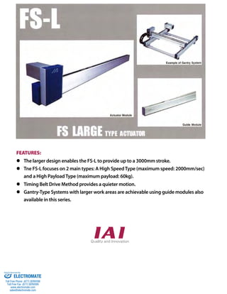
1. FEATURES:
The larger design enables the FS-L to provide up to a 3000mm stroke.
Tne FS-L focuses on 2 main types: A High Speed Type (maximum speed: 2000mm/sec)
and a High Payload Type (maximum payload: 60kg).
Timing Belt Drive Method provides a quieter motion.
Gantry-Type Systems with larger work areas are achievable using guide modules also
available in this series.
Sold & Serviced By:
ELECTROMATE
Toll Free Phone (877) SERVO98
Toll Free Fax (877) SERV099
www.electromate.com
sales@electromate.com
2. Model
Specification
Items
FS-1 FS-LM-400
FS
Single-axis robot / Slim belt type / Actuator width: 75mm / 400W
High payload specification
400
Series Stroke
135
133 2
Applicable controller
T1: XSEL-J/K
T2: SCON
SSEL
XSEL-P/Q
11LM (Single slider) 12LM (Double slider)
85
15 15
85
15 15
20 20 20 20 90
Free slider Drive slider
5-M8, depth 12 10-M8, depth 12
*2 The dimension inside of ( ) indicates 12LM. 209.4
1000: 1000mm
3000: 3000mm
(in 100mm increments)
A 160
D 120 160
Encoder type
A: Absolute
specification
I: Incremental
specification
Motor type
400: 400W
20
C: Stroke 85(170*2) 20
ME SE SE ME *3
184
75
25
40±0.3
10.2±0.3
20.2±0.3
10
T-slot
24
54 B 150 10 23
49.4
122.5 86.9
ø35
(300)
61
61
6 7
98
22 221
243
Cable joint connector *1
T-slot dimension
FS-11LM-400
Stroke 1000
ABCD
Mass (kg)
Payload (kg)
1549
1325
1000
1085
28
1500
2049
1825
1500
1585
34
2000
2549
2325
2000
2085
40
2500
3049
2825
2500
2585
47
3000
3549
3325
3000
3085
53
15
FS-12LM-400
*1
Connect the motor cable and encoder cable.
Refer to P. FS-7 & FS-8 for the cables.
60 44 36 28
Stroke 1000
ABCD
Mass (kg)
Payload (kg)
1649
1425
1015
1185
31
1500
2149
1925
1515
1685
37
2000
2649
2425
2015
2185
43
2500
3149
2925
2515
2685
49
3000
3649
3425
3015
3185
56
* 1000~3000mm strokes are available in 100mm increments.
Dimensions A~D increase by 100mm for every 100mm stroke increment.
(Note 1) The payload is the value when operated at 0.3 G acceleration.
(Note 2) Note that when the stroke increases, the payload will drop.
(Refer to the tables above for payload by stroke.)
(Note 3) The maximum cable length is 30 m. Specify a desired length
in meters. (Example. X08 = 8 m)
Applicable Controller Specifications
Applicable
Maximum number
Connectable
Controller
of controlled axes
encoder type
Operating
method
Power-supply
voltage
Reference
page
X-SEL-P/Q 6 axes
Absolute/
incremental
Program
Single/three-phase
200 VAC —
X-SEL-J/K 4 axes Single-phase
100/200 VAC
—
SSEL 2 axes —
SCON 1 axis Positioner pulse
train control
Single-phase
200 VAC —
Diagram
SE: Stroke End
ME: Mechanical End
*3
During the home return, the slider moves to
the ME, so pay attention not to let the slider
hit surrounding parts.
FS-LM-400
Model Number/Specification
Option
Positioning repeatability ±0.08mm
Drive method Timing belt
Lost Motion 0.1mm max.
Allowable static load moment Refer to P. FS-4 (Technical Reference)
Allowable dynamic load moment Refer to P. FS-5 (Technical Reference)
Overhang load length Refer to P. FS-5 (Technical Reference)
Base Material: Aluminum, with white alumite treatment
Applicable controller T1: XSEL-J/K T2: XSEL-P/Q, SSEL, SCON
Cable length (Note 3) N: None, S: 3m, M: 5m, X: Specified length
Ambient operating temperature/humidity 0 to 40°C, 85%RH max. (non-condensing)
Name Model
number
Reference
page Notes
Reversed-home specification NM —
Available for11LM only
No motor (cover only) NQ —
Motor positioned on the opposite side R —
Motor positioned at the bottom U — Custom-order
Cable length
N : None
S : 3m
M : 5m
X: Specified length
Options
Refer to the options
table below.
* In the above model numbers, indicates the encoder type, indicates the stroke, indicates the applicable controller, indicates the cable length, and indicates the option(s).
Common Specifications
Type
11LM: Single slider
specification
12LM: Double slider
specification
Model number Encoder
type
Motor
output
(W)
Slider
Stroke in
100mm
increments
(mm)
Speed
(mm/s)
Payload (Note 1)
Rated
thrust (N)
Horizontal (kg) Vertical (kg)
FS-11LM- - 400- - - - Absolute
Incremental 400
Single
1000~3000 1~1250
15 Designed
exclusively for
horizontal use
196
FS-12LM- - 400- - - - Double 60 (Note 2)
* Refer to P. FS-6 for the actuator
installation method.
Sold & Serviced By:
ELECTROMATE
Toll Free Phone (877) SERVO98
Toll Free Fax (877) SERV099
www.electromate.com
sales@electromate.com
3. Options
Stroke in
100mm
increments
(mm)
Speed
(mm/s)
Payload (Note 1)
Rated
thrust (N)
Horizontal (kg) Vertical (kg)
1000~3000 1~2000
10 Designed
exclusively for
horizontal use
127
FS-12HM- - 400- - - - Double 40 (Note 2)
11HM (Single slider) 12HM (Double slider)
5-M8, depth 12 Free slider Drive slider
49.4
209.4
*1
Connect the motor cable and encoder cable.
Refer to P. FS-7 & FS-8 for the cables.
2500
3149
2925
2515
2685
49
3000
3649
3425
3015
3185
56
FS-2 FS-HM-400
400
Series Encoder type
Motor type
Stroke
Model number Encoder
type
Motor
output
(W)
Slider
FS-11HM- - 400- - - - Absolute
Incremental 400
Single
FS-11HM-400 FS-12HM-400
Stroke 1000
ABCD
Mass (kg)
Payload (kg)
1549
1325
1000
1085
28
1500
2049
1825
1500
1585
34
2000
2549
2325
2000
2085
40
2500
3049
2825
2500
2585
47
3000
3549
3325
3000
3085
53
Stroke 1000
ABCD
Mass (kg)
Payload (kg)
1649
1425
1015
1185
31
1500
2149
1925
1515
1685
37
2000
2649
2425
2015
2185
43
10 40 30 25 20
135
Model
Specification
Items
133 2
15 85 15
A
160
D 120 160
20
C: Stroke 85(170*2) 20
ME SE SE ME *3
11HM: Single slider
specification
12HM: Double slider
specification
184
75
25
40±0.3
10.2±0.3
20.2±0.3
10
Type
T-slot
24
54 B 150 10
23
122.5 86.9
*2 The dimension inside of ( ) indicates 12HM.
10-M8, depth 12
20 20
90
ø35
(300)
61
61
6 7
98
22 221
243
Cable joint connector *1
T-slot dimension
15 85 15
20 20
* 1000~3000mm strokes are available in 100mm increments.
Dimensions A~D increase by 100mm for every 100mm stroke increment.
(Note 1) The payload is the value when operated at 0.3 G acceleration.
(Note 2) Note that when the stroke increases, the payload will drop.
(Refer to the tables above for payload by stroke.)
(Note 3) The maximum cable length is 30 m. Specify a desired length
in meters. (Example. X08 = 8 m)
Applicable Controller Specifications
Applicable
Maximum number
Connectable
Controller
of controlled axes
encoder type
Operating
method
Power-supply
voltage
Reference
page
X-SEL-P/Q 6 axes
Absolute/
incremental
Program
Single/three-phase
200 VAC —
X-SEL-J/K 4 axes Single-phase
100/200 VAC
—
SSEL 2 axes —
SCON 1 axis Positioner pulse
train control
Single-phase
200 VAC —
Diagram
SE: Stroke End
ME: Mechanical End
*3
During the home return, the slider moves to
the ME, so pay attention not to let the slider
hit surrounding parts.
FS-HM-400
Model Number/Specification
A: Absolute
specification
I: Incremental
specification
1000: 1000mm
3000: 3000mm
(in 100mm increments)
FS
400: 400W
Applicable controller
T1: XSEL-J/K
T2: SCON
SSEL
XSEL-P/Q
Cable length
N : None
S : 3m
M : 5m
X: Specified length
Refer to the options
table below.
* In the above model numbers, indicates the encoder type, indicates the stroke, indicates the applicable controller, indicates the cable length, and indicates the option(s).
* Refer to P. FS-6 for the actuator
installation method.
Single-axis robot / Slim belt type / Actuator width: 75mm / 400W
High speed specification
Option
Positioning repeatability ±0.08mm
Drive method Timing belt
Lost Motion 0.1mm max.
Allowable static load moment Refer to P. FS-4 (Technical Reference)
Allowable dynamic load moment Refer to P. FS-5 (Technical Reference)
Overhang load length Refer to P. FS-5 (Technical Reference)
Base Material: Aluminum, with white alumite treatment
Applicable controller T1: XSEL-J/K T2: XSEL-P/Q, SSEL, SCON
Cable length (Note 3) N: None, S: 3m, M: 5m, X: Specified length
Ambient operating temperature/humidity 0 to 40°C, 85%RH max. (non-condensing)
Name Model
number
Reference
page Notes
Reversed-home specification NM —
Available for11HM only
No motor (cover only) NQ —
Motor positioned on the opposite side R —
Motor positioned at the bottom U — Custom-order
Common Specifications
Sold & Serviced By:
ELECTROMATE
Toll Free Phone (877) SERVO98
Toll Free Fax (877) SERV099
www.electromate.com
sales@electromate.com
4. FS-LO
Model
Specification
Items
FS
Single-axis robot / Actuator width: 75mm / Guide module
0
Series Type
Stroke
11LO: Single slider
specification
12LO: Double slider
specification
Model Number/Specification
Model number Encoder
type
* In the above model numbers, indicates the stroke.
Diagram
FS-3 FS-LO
1000: 1000mm
3000: 3000mm
(in 100mm increments)
Motor type
0: No motor
Motor
output
(W)
Slider
11LO (Single slider) 12LO (Double slider)
85
85
20 20
5-M8, depth 12 Free slider Free slider
184 D 130
FS-11LO-0 FS-12LO-0
Stroke 1000
ABCD
Mass (kg)
Payload (kg)
1403
1379
1000
1085
19
1500
1903
1879
1500
1585
25
2000
2403
2379
2000
2085
31
2500
2903
2879
2500
2585
38
3000
3403
3379
3000
3085
44
−
Stroke 1000
ABCD
Mass (kg)
Payload (kg)
1503
1479
1015
1185
22
1500
2003
1979
1515
1685
28
2000
2503
2479
2015
2185
34
2500
3003
2979
2525
2685
40
3000
3503
3479
3025
3185
46
−
Applicable Controller Specifications
Applicable
Maximum number
Connectable
Controller
of controlled axes
encoder type
* 1000~3000mm strokes are available in 100mm increments.
Dimensions A~D increase by 100mm for every 100mm stroke increment.
Operating
method
Power-supply
voltage
Reference
page
— — — — — —
— — — — — —
— — — — — —
Stroke in
100mm
increments
(mm)
Speed
(mm/s)
Payload (Note 1)
Rated
thrust (N)
Horizontal (kg) Vertical (kg)
FS-11LO-0-
— —
Single
1000~3000 — — — —
FS-12LO-0- Double
135
133 2
15 15
A
20 85 20
ME SE SE ME
75
25
40±0.3
10.2±0.3
20.2±0.3
10
T-slot
24
B 10
10-M8, depth 12
20 20
15 15
6 7
T-slot dimension
SE: Stroke End
ME: Mechanical End
Option
Positioning repeatability —
Drive method —
Lost Motion —
Allowable static load moment Refer to P. FS-4 (Technical Reference)
Allowable dynamic load moment Refer to P. FS-5 (Technical Reference)
Overhang load length Refer to P. FS-5 (Technical Reference)
Base Material: Aluminum, with white alumite treatment
Cable length —
Ambient operating temperature/humidity 0 to 40°C, 85%RH max. (non-condensing)
Name Model
number
Reference
page Notes
Common Specifications
* Refer to P. FS-6 for the actuator
installation method.
Sold & Serviced By:
ELECTROMATE
Toll Free Phone (877) SERVO98
Toll Free Fax (877) SERV099
www.electromate.com
sales@electromate.com
5. Technical Reference
Allowable Dynamic Moment and Allowable Static Moment
There are two types of moment that can be applied to the the guide: the allowable dynamic moment and the allowable static moment.
The allowable dynamic moment is calculated from the travel life (when aking occurs) when moved with the moment load applied.
In contrast, the static moment is calculated from the load that causes permanent deformation to the steel ball or its rolling surface (i.e. rated static
moment), taking into account the rigidity and deformity of the base.
[Allowable Dynamic Moment]
IAI's catalog contains the allowable dynamic moments based on a load coecient of 1.2 and 10,000km or 5,000km.
This value is dierent from the so-called basic rated dynamic moment, which is based on a 50km travel life.
To calculate the basic rated dynamic moment for a 50km travel life, use the following equation.
M50 = fw × MS ÷
MS
S
fw
M50
1
( 50 )3
S
: Allowable dynamic moment at an assumed travel distance (catalog value)
• • • • Equation 1 : IAI catalog assumed travel life (5,000km or 10,000km)
: Load coecient (=1.2)
: Basic rated dynamic moment (50km travel life)
The allowable dynamic moments mentioned in the catalog (10,000km or 5,000km life) are based on a load coecient fw=1.2. To
calculate the service life of a guide with a dierent load coecient, use Table 1 below to determine the load coecient that matches
your requirements.
Operation and Load Requirements Load Coecient fw
Table 1: Load Coecients
Slow operation with light vibration/shock (1500mm/s or less, 0.3G or less) 1.0~1.5
Moderate vibration/shock, abrupt braking and accelerating (2500mm/s or less, 1.0G or less)
Operation with abrupt acceleration/deceleration with heavy vibration/shock (2500mm/s or faster, 1.0G or faster)
( CIA 3
•
1.2 )
L10 = P fw
x S • • • • Equation (2)
L10 : Service life (90% Survival Probability)
1.5~2.0
2.0~3.5
CIA
P
S
fw
: Allowable dynamic moment in IAI Catalog (5,000km or 10,000km)
: Moment used (› CIA)
: IAI catalog assumed travel life (5,000km or 10,000km)
: Load coecient (from Table 1)
The maximum moment that can be applied to a slider at rest.
These values are calculated by taking the basic rated static moment of the slider and multiplying with the safety rate that takes into
consideration any eects from the rigidity and deformity of the base.
Therefore, if a moment load is applied to the slider at rest, keep the moment within this allowable static moment. However, use caution
to avoid adding any unexpected shock load from any inertia that reacts on the load.
FS-4 Technical Reference
[Allowable Static Moment]
[Basic Rated Static Moment]
The basic rated static moment is the moment value at which the sum of the permanent deformation at the center of contact between
the rolling body (steel ball) and the rolling surface (rail) is 0.0001 times the diameter of the rolling body.
These values are simply calculated strictly from the permanent deformation done to the steel ball and its rolling surface. However, the
actual moment value is restricted by the rigidity and deformation of the base. Hence, the allowable static moment the actual moment
that can be applied statically, taking into account those factors.
Sold Serviced By:
ELECTROMATE
Toll Free Phone (877) SERVO98
Toll Free Fax (877) SERV099
www.electromate.com
sales@electromate.com
6. Technical Reference
Allowable dynamic moment, Overhang load length
With each type of FS Series, a single or double slider can be selected.
The allowable dynamic moment and overhang load length vary depending on the length of the slider.
Refer to the typical examples shown below.
Directions of allowable dynamic moments
Allowable dynamic moment values are based on a 20,000 km service life. Please note that
applying a moment exceeding the allowable value will reduce the service life of the guide.
Directions of load moments
Type
FS-11NM
FS-11NO
FS-12NM
FS-12NO
FS-11WM
FS-11WO
FS-12WM
FS-12WO
FS-11LM
FS-11LO
FS-11HM
FS-5 Technical Reference
Overhang load length
When each model is used with an overhang load exceeding the
allowable length, vibration may occur. Be sure to keep the
overhang load length within the allowable value.
Double slider (Fig. 2)
MA MB MC
L
L
Single slider (Fig. 1)
Overhang L
mm
Ma, Mb, Mc directions: 200mm or less
Ma, Mb, Mc directions: 500mm or less
Ma, Mb, Mc directions: 240mm or less
Ma, Mb, Mc directions: 600mm or less
Ma, Mb, Mc directions: 300mm or less
(*) For case of 20,000km service life (fw=1.2)
FS-12LM
FS-12LO
FS-12HM
Fig. 1 Single slider
Fig. 2
Double slider
(when sliders are
joined together)
Fig. 1 Single slider
Fig. 2
Double slider
(when sliders are
joined together)
Fig. 1 Single slider
Fig. 2
Double slider
(when sliders are
joined together)
Allowable dynamic moment (*)
N•m (Kgf•m)
Ma: 2.9 (0.3)
Mb: 2.9 (0.3)
Mc: 4.5 (0.46)
Ma: 20.5 (2.1)
Mb: 18.6 (1.9)
Mc: 9.1 (0.93)
Ma: 4.4 (0.45)
Mb: 3.9 (0.4)
Mc: 5.8 (0.6)
Ma: 27.4 (2.8)
Mb: 25.4 (2.6)
Mc: 11.7 (1.2)
Ma: 8.8 (0.9)
Mb: 7.8 (0.8)
Mc: 12.7 (1.3)
Ma: 51.9 (5.3)
Mb: 47.0 (4.8)
Mc: 25.4 (2.6)
Ma, Mb, Mc directions: 750mm or less
FS Series Technical Refernce
Sold Serviced By:
ELECTROMATE
Toll Free Phone (877) SERVO98
Toll Free Fax (877) SERV099
www.electromate.com
sales@electromate.com
7. FS Actuator Installation Method / Mounting Orientation
Quantity
5
6
7
8
9
: Installable —: Not installable
FS-6 Technical Reference
NM, NO, WM, WO, LM, LO, HM
T-nut (standard accessory)
FS
Technical Reference
Installtion method
FS Series
Using the T-groove on the back of
the base, secure the body with the
T-nut supplied with the actuator.
FS-NM (T-slot 1 line) : T-nut M8
FS-NO (T-slot 1 line) : T-nut M8
FS-WM (T-slot 1 line) : T-nut M8
FS-WO (T-slot 1 line) : T-nut M8
FS-LM (T-slot 2 lines) : T-nut M8
FS-LO (T-slot 2 lines) : T-nut M8
FS-HM (T-slot 2 lines) : T-nut M8
Quantity of T-nut included
Stroke
300~1000
1100~1500
1600~2000
2100~2500
2600~3000
* Double the numbers for LM/LO/HM models.
Orientation
Mounting orientation
Series Type Horizontal, flat Vertical Side-mounted Ceiling mounted
HL-400
HM-400
LO
FS — —
Sold Serviced By:
ELECTROMATE
Toll Free Phone (877) SERVO98
Toll Free Fax (877) SERV099
www.electromate.com
sales@electromate.com
8. Spare Parts
Motor cable (for XSEL-J/K/P/Q, SSEL, SCON)
(41)
Minimum bend radius R: r = 51mm or larger (for movable use)
Encoder cable (for XSEL-J/K)
(36.8)
Limit switch cable (for XSEL-J/K)
Model: CB-X-LC
(22)
(18) (12) (8)
FS-7 Spare Parts
Color No. Signal Color Wire
Wire Signal No.
——————
SD
SD
BAT+
BAT-VCC
GND
BK-BK+
—
123456789
10
11
12
13
14
15
——————
Blue
Orange
Black
Yellow
Green
Brown
Gray
Red
—
123456789
BAT+
BAT-SD
SD
VCC
GND
FG
BK-BK+
Black
Yellow
Blue
Orange
Green
Brown
Ground
Gray
Red
(20) (10)
(14) (8)
1
9
(16)
(42)
L
L
(36)
(ø8)
(25)
(ø9)
(21)
(Front view) (Front view)
(18)
Wire Signal No.
Controller side Mechanical side
0.15sq
(crimped)
0.15sq
(crimped)
Color
No. Signal
The shield is clamped to the hood Braided ground shield wire
Color Wire
1
1
4
4
1
(16)
(Front view) (Front view)
234
1234
UVW
PE
Red
White
Black
Green
PE
Controller side Mechanical side
0.75sq 0.75sq
(crimped)
UVW
Green
Red
White
Black
Motor Cable / Encoder Cable
These are joint cables to connect the actuator cable joint connector and the controller.
There are two kinds of cables; a motor cable for the motor power, and an encoder cable for the encoder signals.
Also, when you use the cable with a cable track, please use the robot cable which is heavy-duty and has excellent bending resistance. (*)
(*) For motor/encoder cables for single-axis robots, all the standard cables are robot cables.
Model: CB-X-MA
* is the cable length (L); supports up to 30m.
Example: 080 = 8m
* is the cable length (L); supports up to 30m.
Example: 080 = 8m
* is the cable length (L); supports up to 30m.
Example: 080 = 8m
Model: CB-X-PA
Minimum bend radius R: r = 44mm or larger (for movable use)
L
(ø6)
(30)
Minimum bend radius R: r = 33mm or larger (for movable use)
1
6
1
6
(12)
(18)
(Front view) (Front view)
Controller side Mechanical side
Color No. Signal Color Wire
123456
Wire Signal No.
654321
24VOUT
N
LS
CREEP
OT
RSV
24VOUT
N
LS
CREEP
OT
RSV
Light Blue
Pink
Light Green
Orange
Gray
1B/Light Blue
Light Blue
Pink
Light Green
Orange
Gray
1B/Light Blue
Note) 1B indicates one black dot mark.
AWG24
AWG24 (crimped)
Sold Serviced By:
ELECTROMATE
Toll Free Phone (877) SERVO98
Toll Free Fax (877) SERV099
www.electromate.com
sales@electromate.com
9. Spare Parts
* is the cable length (L); supports up to 30m.
Example: 080 = 8m
* is the cable length (L); supports up to 30m.
Example: 080 = 8m
No. Signal Color Wire
White/Blue
White/Yellow
White/Red
White/Black
White/Purple
White/Gray
Color Wire
FS-8 Spare Parts
Encoder cable (for XSEL-P/Q, SSEL, SCON)
Model: CB-X1-PA
L
Minimum bend radius R: r = 44mm or larger (for movable use)
Wire Signal No.
Encoder Cable (for XSEL-P/Q, SSEL, SCON, and LS equipped connection)
Model: CB-X1-PLA
L
(ø8)
Minimum bend radius R: r = 54mm or larger (for movable use)
1
1
13
14
26
9
(13)
(41)
(Front view) (Front view)
Plug housing: XMP-09V (Nichiatsu)
Socket contact: BXA-001T-P0.6 (Nichiatsu) x 9
Retainer: XMS-09V (Nichiatsu)
(37)
(ø8)
(25)
(14)
(8)
Controller side Mechanical side
10
11
12
13
26
25
24
23
9
18
19
12345678
14
15
16
17
20
21
22
123456789
BAT+
BAT-SD
SD
VCC
GND
FG
BK-BK+
Purple
Gray
Orange
Green
Red
Black
Ground
Blue
Yellow
—————————————————
Orange
Green
Purple
Gray
Red
Black
Blue
Yellow
—
——
E24V
OV
LS
CREEP
OT
RSV
———
A+
A-B+
B-Z+
Z-SRD+
SRD-BAT+
BAT-VCC
GND
BKR-BKR+
—
AWG26
(crimped)
AWG26
(soldered)
Color
No. Signal
Braided ground shield wire
The shield is clamped to the hood
Color Wire
(14)
1
1
13
14
26
9
1
6
(13)
(41)
(37)
(25) (18)
(8)
L S side
(Front view) (Front view)
Controller side Mechanical side
Wire Signal No.
10
11
12
13
26
25
24
23
9
18
19
1
2
3
4
5
6
7
8
14
15
16
17
20
21
22
1
2
3
4
5
6
1
2
3
4
5
6
7
8
9
E24V
OV
LS
CREEP
OT
RSV
BAT+
BAT-SD
SD
VCC
GND
FG
BK-BK+
Purple
Gray
Orange
Green
Red
Black
Ground
Blue
Yellow
—
—
White/Blue
White/Yellow
White/Red
White/Black
White/Purple
White/Gray
—
—
—
—
—
—
—
—
—
Orange
Green
Purple
Gray
Red
Black
Blue
Yellow
—
—
—
E24V
OV
LS
CREEP
OT
RSV
—
—
—
A+
A-B+
B-Z+
Z-SRD+
SRD-BAT+
BAT-VCC
GND
BKR-BKR+
—
AWG26
(crimped)
AWG26
(soldered)
Color
No. Signal
Braided ground shield wire
The shield is clamped to the hood
(White/Blue in cable color indicates the colors of line/insulator.)
AWG26
(crimped)
Sold Serviced By:
ELECTROMATE
Toll Free Phone (877) SERVO98
Toll Free Fax (877) SERV099
www.electromate.com
sales@electromate.com