Download to read offline
![International Research Journal of Engineering and Technology (IRJET) e-ISSN: 2395-0056
Volume: 06 Issue: 09 | Sep 2019 www.irjet.net p-ISSN: 2395-0072
© 2019, IRJET | Impact Factor value: 7.34 | ISO 9001:2008 Certified Journal | Page 24
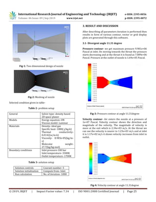
PERFORMANCE ANALYSIS OF CONVERGING DIVERGING NOZZLE
Mohini1, Er Kriti Srivastava2, Er Shweta Mishra3, Er Akhil Vikram Yadav4
1M. Tech student, Mechanical Engineering, IET Dr. R.M.L Avadh University, Ayodhya, India
2,3 &4Assistant Professor, Mechanical Engineering Dept., IET Dr. R.M.L Avadh University, Ayodhya, India
----------------------------------------------------------------------***-------------------------------------------------------------------------
Abstract:- Nozzle produced thrust and convert thermal energy of hot gases into kinetic energy. The purpose of nozzle is to
expand gases as efficiently as possible to maximize exit velocity. Nozzle is useful in supersonic flow to attain speed greater
than the speed of sound. Computational fluid dynamics (CFD), is use to compute flow of nozzle with different mach numbers
and different divergent angle of the nozzle. In the present work, CD nozzle is designed by using CFD for a particular divergent
angle in 2D model. Further analysis and comparison is done for various other cases by changing divergent angle of nozzle. CFD
replaces continuous domain with discrete using grid, numerical methods and algorithms to solve and analyze problems
involving in fluid flow. In this dissertation work is carried out in ANSYS Fluent 15.0 for modeling and analysis of flow for
supersonic nozzle.
KEY WORDS: Convergent divergent nozzle, degree of angle, Mach number, computational fluid dynamics.
1. INTRODUCTION
A nozzle is used to control the direction of flow, mass,
shape, pressure, rate of flow and speed of the stream that
is exhausted from nozzle. Flow velocity increases means
some other form of energy must decreases. In this case
temperature and pressure both will decreases and velocity
increases. [1] A De-Laval nozzle is an example of CD nozzle
which was invented by a Swedish inventor Gustaf De-
Laval. In all modern rocket engine that used hot gas
combustion use de-level nozzle. The gas flow through a de-
level nozzle is isentropic(less friction and less heat
dissipation). De-Laval nozzle works on converting
pressure energy from the fuel flow and heat energy from
the combustion of fuel into kinetic energy in the form of
high exhaust velocity.[2] In converging section of nozzle
area is decreasing to minimum and then area is expanding
back out to maximum in diverging section.[3] Engines are
most efficient when the exhaust is at the same pressure as
the ambient pressure outside of the engines so for rocket
engines which will be used at sea level where ambient
pressure is relatively high the expansion ratio will be
pretty low so the exhaust stays at about one atmosphere
pressure when it leaves the nozzle for rocket engine which
will be used in the upper atmospheric or in space the
ambient pressure will be must lower so the expansion
ratio will be much higher. This is why upper stage engines
usually have a very large engine pill, first stage engines
have to work at a variety of pressure as they climb through
the atmosphere is only one pressure where these engines
have maximum efficiency, all other altitudes they run at
slightly lower efficiency there have been some attain to
minimize these loss by designing engine nozzle that work
well at altitude. So the nozzle is very important part of the
rocket engine which is use to take the heat and pressure
produce by all other parts of the engine and transform all
of that energy into thrust.
2. METHODOLOGY ADOPTED
In the present study, the certain methodology has been
followed which give optimum result to complete our study
for CFD analysis of CD nozzle. First a 2-D model is
generated by using ANSYS software then mesh is created,
next step is defining operating condition, material
selection, and boundary condition for solving the equation,
after that result is analyzed. Deshpande ND et. al [2018]
reported that results obtained by theoretical data are
almost same as result obtained by (CFD) analysis. [4] We
have used these data in for the designing of nozzle.
Table 1 dimension of nozzle
Parameter dimension
Diameter of inlet 166.6(mm)
Diameter of throat 34.5(mm)
Diameter of outlet 183(mm)
Length of chamber 99.93(mm)
Convergent angle 32o
Divergent angle 11.31o](https://image.slidesharecdn.com/irjet-v6i906-191205091820/85/IRJET-Performance-Analysis-of-Converging-Diverging-Nozzle-1-320.jpg)
![International Research Journal of Engineering and Technology (IRJET) e-ISSN: 2395-0056
Volume: 06 Issue: 09 | Sep 2019 www.irjet.net p-ISSN: 2395-0072
© 2019, IRJET | Impact Factor value: 7.34 | ISO 9001:2008 Certified Journal | Page 24
PERFORMANCE ANALYSIS OF CONVERGING DIVERGING NOZZLE
Mohini1, Er Kriti Srivastava2, Er Shweta Mishra3, Er Akhil Vikram Yadav4
1M. Tech student, Mechanical Engineering, IET Dr. R.M.L Avadh University, Ayodhya, India
2,3 &4Assistant Professor, Mechanical Engineering Dept., IET Dr. R.M.L Avadh University, Ayodhya, India
----------------------------------------------------------------------***-------------------------------------------------------------------------
Abstract:- Nozzle produced thrust and convert thermal energy of hot gases into kinetic energy. The purpose of nozzle is to
expand gases as efficiently as possible to maximize exit velocity. Nozzle is useful in supersonic flow to attain speed greater
than the speed of sound. Computational fluid dynamics (CFD), is use to compute flow of nozzle with different mach numbers
and different divergent angle of the nozzle. In the present work, CD nozzle is designed by using CFD for a particular divergent
angle in 2D model. Further analysis and comparison is done for various other cases by changing divergent angle of nozzle. CFD
replaces continuous domain with discrete using grid, numerical methods and algorithms to solve and analyze problems
involving in fluid flow. In this dissertation work is carried out in ANSYS Fluent 15.0 for modeling and analysis of flow for
supersonic nozzle.
KEY WORDS: Convergent divergent nozzle, degree of angle, Mach number, computational fluid dynamics.
1. INTRODUCTION
A nozzle is used to control the direction of flow, mass,
shape, pressure, rate of flow and speed of the stream that
is exhausted from nozzle. Flow velocity increases means
some other form of energy must decreases. In this case
temperature and pressure both will decreases and velocity
increases. [1] A De-Laval nozzle is an example of CD nozzle
which was invented by a Swedish inventor Gustaf De-
Laval. In all modern rocket engine that used hot gas
combustion use de-level nozzle. The gas flow through a de-
level nozzle is isentropic(less friction and less heat
dissipation). De-Laval nozzle works on converting
pressure energy from the fuel flow and heat energy from
the combustion of fuel into kinetic energy in the form of
high exhaust velocity.[2] In converging section of nozzle
area is decreasing to minimum and then area is expanding
back out to maximum in diverging section.[3] Engines are
most efficient when the exhaust is at the same pressure as
the ambient pressure outside of the engines so for rocket
engines which will be used at sea level where ambient
pressure is relatively high the expansion ratio will be
pretty low so the exhaust stays at about one atmosphere
pressure when it leaves the nozzle for rocket engine which
will be used in the upper atmospheric or in space the
ambient pressure will be must lower so the expansion
ratio will be much higher. This is why upper stage engines
usually have a very large engine pill, first stage engines
have to work at a variety of pressure as they climb through
the atmosphere is only one pressure where these engines
have maximum efficiency, all other altitudes they run at
slightly lower efficiency there have been some attain to
minimize these loss by designing engine nozzle that work
well at altitude. So the nozzle is very important part of the
rocket engine which is use to take the heat and pressure
produce by all other parts of the engine and transform all
of that energy into thrust.
2. METHODOLOGY ADOPTED
In the present study, the certain methodology has been
followed which give optimum result to complete our study
for CFD analysis of CD nozzle. First a 2-D model is
generated by using ANSYS software then mesh is created,
next step is defining operating condition, material
selection, and boundary condition for solving the equation,
after that result is analyzed. Deshpande ND et. al [2018]
reported that results obtained by theoretical data are
almost same as result obtained by (CFD) analysis. [4] We
have used these data in for the designing of nozzle.
Table 1 dimension of nozzle
Parameter dimension
Diameter of inlet 166.6(mm)
Diameter of throat 34.5(mm)
Diameter of outlet 183(mm)
Length of chamber 99.93(mm)
Convergent angle 32o
Divergent angle 11.31o](https://image.slidesharecdn.com/irjet-v6i906-191205091820/75/IRJET-Performance-Analysis-of-Converging-Diverging-Nozzle-1-2048.jpg)
![International Research Journal of Engineering and Technology (IRJET) e-ISSN: 2395-0056
Volume: 06 Issue: 09 | Sep 2019 www.irjet.net p-ISSN: 2395-0072
© 2019, IRJET | Impact Factor value: 7.34 | ISO 9001:2008 Certified Journal | Page 26
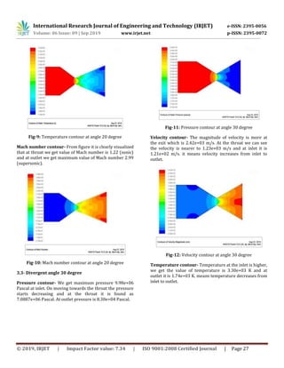
Temperature contour- Temperature at the inlet is higher,
we get the value of temperature is 3.30e+03 K and at
outlet it is 1.85e+03 K, means temperature decreases from
inlet to outlet.
Fig-5: Temperature contour at angle 11.31degree
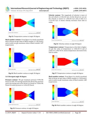
Mach number contour- From figure it is clearly visualized
that at throat we get value of Mach number is 1.21 (sonic)
and at outlet we get maximum value of Mach number 2.87
(supersonic). Mach no increases from inlet to outlet. [5]
Fig-6: Mach number contour at angle 11.31degree
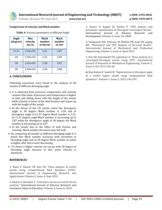
3.2- Divergent angle 20 degree
Pressure contour- We get maximum pressure 9.981e+06
Pascal at inlet. On moving towards the throat the pressure
starts decreasing and at the throat it is found as 7.88e+06
Pascal. At outlet pressure is 1.07e+05 Pascal.
Fig-7: Pressure contour at angle 20 degree
Velocity contour- The magnitude of velocity is more at
the exit which is 2.39e+03 m/s. At the throat we can see
the velocity is nearer to 1.23e+03 m/s and at inlet it is
1.19e+02 ms. it means velocity increases from inlet to
outlet.
Fig-8: Velocity contour at angle 20 degree
Temperature contour- Temperature is higher at the inlet,
we get the value of temperature is 3.30e+03 K and at
outlet it is 1.79e+03 K means temperature decreases on
moving inlet to outlet.](https://image.slidesharecdn.com/irjet-v6i906-191205091820/85/IRJET-Performance-Analysis-of-Converging-Diverging-Nozzle-3-320.jpg)

This document analyzes the performance of converging-diverging nozzles with different divergent angles using computational fluid dynamics (CFD). It discusses the methodology used, which involves generating 2D nozzle models in ANSYS, meshing, defining operating conditions and boundary conditions. CFD analysis is performed for nozzles with divergent angles of 11.31, 20, 30, and 40 degrees. The results show that pressure and temperature decrease along the nozzle from inlet to outlet, while velocity increases. A divergent angle of 30 degrees produces the highest Mach number at the outlet of 3.07. Increasing the divergent angle initially increases the Mach number but it starts decreasing after 30 degrees.


