Download to read offline

![Hassan A. Khayyat and Ikramuddin Sohail Md
http://www.iaeme.com/IJMET/index.asp 244 editor@iaeme.com
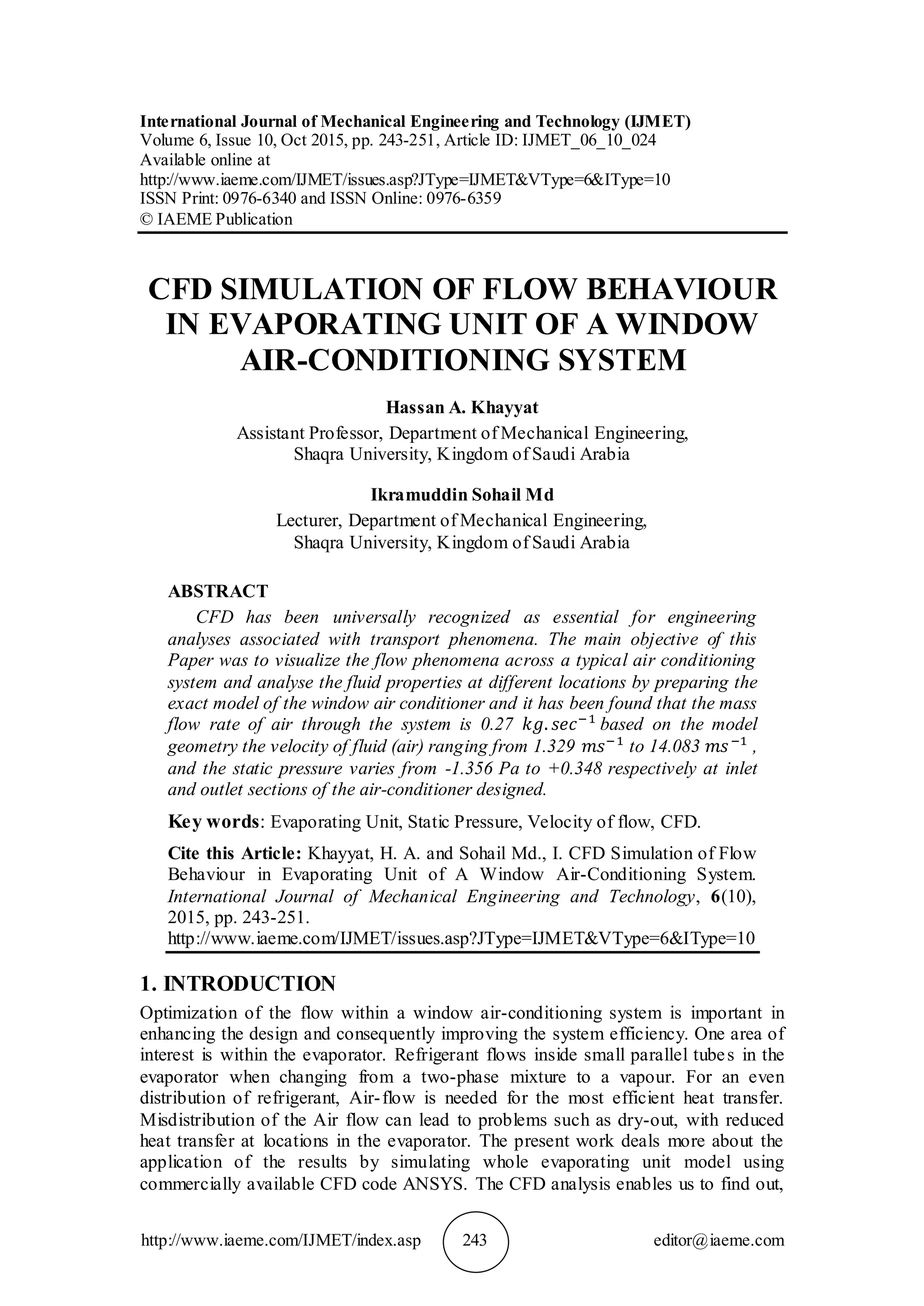
on an average base, the performance of an actually operating heat exchanger. We can
also come to know the temperatures at any points in heat exchanger. However, the
results available through CFD analysis are for the ideal condition, i.e. for no-loss
operating condition. For this analysis, whole evaporating unit is selected and divided
into domains and meshed with ANSYS-ICEM-12.0 with a number of elements. The
material properties and boundary conditions are applied and the domain is solved by
using ANSYS-CFX-12.0 to satisfy continuity, momentum and energy equations. This
powerful tool along with faster and robust digital computers makes it possible to
predict velocity of air flowing across the whole domain.
Barbosa et al. (1 ) investigated the influence of geometric parameters, such as the
number of tube rows, fin pitch, number of fins and air flow rate, on the airside
thermalhydraulic performance of eight tubefin 'nofrost' evaporator samples. The
experimental data was correlated in terms of the Colburn factor, j, and the Darcy
friction factor, ƒ, through empirical correlations with ±7% error.
Yashar at al [2] presented a comparable evaluation of R600a (isobutene), R290
(propane), R134a, R22, R410A, and R32 in an optimized finned-tube evaporator, and
Analyzes the impact of evaporator effects on the System coefficient of performance
(COP), The study relied on a detailed evaporator model derived from NIST’s EVAP-
COND simulation package and used the ISHED1 scheme employing a non-Darwinian
learnable evolution model for circuitry optimization. Karatas, H., [3] Shih [4] and
Kim, Y [5] did similar research in the field of CFD.
2. SCHEMATIC MODEL FOR ANALYSIS
The schematic model picture of a typical window Air-Conditioner and the
evaporating unit transverse sections are shown as here under.
3. EVAPORATOR-WORKING AND DESIGN:
Evaporator is a heat transfer surface in which a volatile liquid is vaporized for the
purpose of removing heat from a refrigerated space or product.
The evaporator absorbs the heat from the air passing through the coil and provides
required degree of superheating of the refrigerant gas to ensure elimination of the
liquid refrigerant entering the compressor. Liquid refrigerant entry will cause damage
to suction valve of compressor.
The evaporator should normally be sized to ensure that the refrigerant returns to
the compressor in a completely gaseous state.
The factors that largely influence the heat transfer rate in a forced convection type
evaporator are](https://image.slidesharecdn.com/ijmet0610024-151114113929-lva1-app6892/85/Ijmet-06-10_024-2-320.jpg)

![CFD Simulation of Flow Behaviour in Evaporating Unit of A Window Air-Conditioning
System
http://www.iaeme.com/IJMET/index.asp 249 editor@iaeme.com
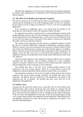
Figure shows the Streamline flow of air inside the evaporating Unit. The Inlet
streamlines are straight and parallel at main inlet domain. As the air passes over the
tubes the streamlines bends and acquires the form of tube surface. The velocity of air
here changes according to continuity equation ( ). As the flow proceeds further
into blower, the velocity of the air coming out of the evaporator coils is increased by the
rotating blower which is rotating at a speed of 1175r.p.m clockwise from the front. The
net velocity between the coils should be between 1.5 m to 3 m for efficient heat
transfer from cooled coils to air at the outlet and is obtained from the results.
Figure 6 Vector flow of air in the system
Figure 7 Velocity Contour inside unit
The vector flow in the whole evaporating unit from the top view is shown above.
The droplets indicate the air flow rate and different colours indicates velocity
magnitude and direction from inlet of the evaporator to the outlet. The air flow
converges at the point of rotation of blower and gets expand in the casing to deliver
the required output flow of air satisfying continuity equation. The velocity contour
and velocity vectors at some plane inside the Blower Casing showing the magnitude
of velocity at various points of flow and the direction. Tabulated Values of various
properties of air across the unit through CFD.
Mass Flow Rate
(kg/s)
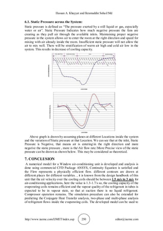
Velocity
(m/s)
Pressure [Pa]
Total Pressure
[Pa]
Inlet 0.27 1.329 -1.056 0.001
Shroud Cone 0.27 1.338 -1.072 0.002
Coil1 in 1 0.27 1.447 -2.732 -1.435
Coil2 in 2 0.27 1.526 -5.127 -3.619
Coil3 in 3 0.27 1.609 -6.774 -5.023
Coil4 in 4 0.27 1.716 -8.687 -6.674
Domain Inlet 0.27 2.52 -11.1 -6.768
Rotary1 0.27 10.858 -73.66 -29.88
Rotary2 0.27 10.536 -67.63 -26.85
Rotary3 0.27 10.12 -53 -27.94
Outlet 0.27 14.083 0.348 120.64](https://image.slidesharecdn.com/ijmet0610024-151114113929-lva1-app6892/85/Ijmet-06-10_024-7-320.jpg)
![CFD Simulation of Flow Behaviour in Evaporating Unit of A Window Air-Conditioning
System
http://www.iaeme.com/IJMET/index.asp 251 editor@iaeme.com
predict the design changes. More accurate analysis can be done by using exact
material properties at locations where temperature is known from experiments.
REFERENCES
[1] Barbosa Jr., J. R., Melo, C. and Hermes, C. J. L. A study of the airside heat
transfer and pressure drop characteristics of tubefin 'nofrost' evaporators. Applied
Energy, 86, 2009, pp. 1484-1491.
[2] Yashar, D., Domanski, P. A. and Kim, M. Performance of finned-tube evaporator
optimized for different refrigerants and its effect on system efficiency.
International Journal of Refrigeration, 2005, pp. 820–827
[3] Karatas, H., Dirik, E. and Derbentil, T. An experimental study of airside heat
transfer and friction factor correlations on domestic refrigerator finnedtube
evaporator coils. Proceedings of the 8th International Refrigeration and Air
Conditioning Conference at Purdue, West Lafayette, IN, July 25-28, 1996.
[4] Shih, Y. C. Numerical study of heat transfer performance on the air side of
evaporator for a domestic refrigerator. Numerical Heat Transfer, Part A, 44,
2003, pp. 851-870.
[5] Kim, Y., Tikhonov, A., Shin, Y. and Lee, J. Experimental study on high
performance defrosting heater for household refrigerator. Proceeding of the 13th
International Heat Transfer Conference, Sydney, Australia, 2006.
[6] Versteeg, H. K., Malalasekera, W. An Introduction to Computational Fluid
Dynamics: The Finite Volume Method. Prentice Hall: Pearson, 1995
[7] Process Heat Transfer,K Q Kern, Prentice hall of India, 2010.
[8] Numerical Heat transfer,Patankar 2009.
[9] Kumar, S., Rajput, S.P.S. and Kumar, A. Thermodynamic Analysis of Year
Round Air Conditioning System for Variable Wet Bulb Temperature of Outlet
Air of Pre-Heating Coil (Cold And Dry Weather). International Journal of
Mechanical Engineering and Technology, 6(4), 2015, pp. 109-116.](https://image.slidesharecdn.com/ijmet0610024-151114113929-lva1-app6892/85/Ijmet-06-10_024-9-320.jpg)

1. The study uses CFD to simulate the flow behavior within the evaporator unit of a window air conditioner. 2. The simulation found that the mass flow rate of air through the system is 0.27 kg/s and the velocity ranges from 1.329 to 14.083 m/s across different locations. 3. The static pressure was found to vary from -1.356 Pa at the inlet to +0.348 Pa at the outlet.


